Tricor 913 User manual
TD-472C (0501)
Model 913 Keyboard & LED
Test System
Operating Instructions
TRICOR Technical Contact
Mark Zatarski
Electronic Technician
1650 Todd Farm Drive
Elgin, Illinois 60123-1145
847 742 5542 Ext. 43
847 742 5574 Fax
TRICOR Systems Inc.
E-mail: markzatarski@tricor-systems.com
Web Page: www.tricor-systems.com

Copyright © 1998 TRICOR Systems Inc.
All rights reserved.
Printed in the United States of America
No part of this publication may be reproduced in any form by any means without the
express permission of TRICOR Systems Inc.
The information in this document is subject to change without notice. TRICOR
Systems Inc. makes no representations or warranties with respect to the contents of
this manual and specifically disclaims any implied warranties of fitness for a
particular purpose. TRICOR Systems Inc. assumes no responsibility for errors or
omissions in this document.
TRICOR Systems Inc.
1650 Todd Farm Drive Elgin, Illinois 60123
Phone (847) 742-5542 • Fax (847) 742-5574
Email: [email protected]
ii
TRICOR Systems Inc.

TRICOR’s Mission Statement emphasizes Quality and
Customer Service. Should you encounter any problems with
your Model 913A Keyboard & LED Test System or
discrepancies in the manual, please let us know at
(847) 742-5542/(800) 575-0161 or Fax (847) 742-5574.
If TRICOR is made aware or discovers any discrepancies or
problems, you will be notified and corrective action will be
taken as soon as possible.
To serve you better we request that primary and alternate
persons to contact be provided on the enclosed product contact
form and returned to TRICOR. This personalized approach will
eliminate any delay in providing you with potentially important
information.
IMPORTANT
iii
TRICOR Systems Inc.

TRICOR WARRANTY REGISTRATION FORM
Customer: ___________________________________________________
Address: ___________________________________________________
___________________________________________________
Please provide the following information for use by our hotline.
• The Serial Number of the
Model 913H Keyboard & LED Test System:
Serial Number ______________
• The person(s) to contact with regard to the
Model 913H Keyboard & LED Test
System and manual:
Name Telephone No. Fax No. Email
Primary ____________________ ____________ ____________ ___________________
Alternate (1) ____________________ ____________ ____________ __________________
(2) ____________________ ____________ ____________ __________________
(3) ____________________ ____________ ____________ __________________
TRICOR Systems Inc.

TRICOR Systems Inc.
iv
Contents
Settings
System Properties ................................................................................................................. 1
Display .................................................................................................................................. 1
Hardware Installation ................................................................................................................. 1
Unit Under Test (UUT) Connection ........................................................................................... 2
Starting the Model 913 Program................................................................................................ 2
Service Mode ................................................................................................................................ 2
Setup Mode .................................................................................................................................. 3
Password Setup in Setup Mode Window ............................................................................. 3
Configuration ........................................................................................................................ 3
Preferences in Setup Mode Window .................................................................................... 4
1. Serial Number Auto Request .................................................................................... 4
2. Display Shorts Test Results on Pass ......................................................................... 4
3. Display LED Voltage Results on Pass...................................................................... 5
4. Display 7-SEG Voltage Results on Pass .................................................................. 5
5. Space Bar = Continue No Save ................................................................................ 5
6. Auto Print Result On Fail ......................................................................................... 5
7. Auto Print Result On Pass ........................................................................................ 5
8. Label Pulse On Fail .................................................................................................. 5
9. Label Pulse On Pass ................................................................................................. 5
10. Test Mode Spanish Screens ...................................................................................... 5
11. Edit Mode - Mouse Move And Place ....................................................................... 5
12. Sound Ding On Pass ................................................................................................. 6
13. Sound Ding On Fail .................................................................................................. 6
14. Short Test Delay Count ............................................................................................ 6
15. Model 911 XY Preferences ...................................................................................... 6
Edit Mode .................................................................................................................................. 6
Altering Keypad Appearance................................................................................................ 6
Edit individual key.............................................................................................................. 11
Edit individual LEDs .......................................................................................................... 12
Edit individual 7-Segment .................................................................................................. 13
Edit Short Channels ............................................................................................................ 14
Learn Mode ................................................................................................................................ 14
Entering Learn Mode .......................................................................................................... 14
Learning the Keys ...............................................................................................................15
Learning the Shorts Test ..................................................................................................... 16
Learning the LEDs.............................................................................................................. 17
Learning the 7-Segments .................................................................................................... 19

TRICOR Systems Inc.
v
Contents Cont'd
Test Mode ................................................................................................................................ 20
Entering Test Mode ............................................................................................................ 20
Shorts Test .......................................................................................................................... 20
Key Test .............................................................................................................................. 21
Test Results ........................................................................................................................ 21
LED Voltage Test ............................................................................................................... 22
LED Visual Test .................................................................................................................23
7-Segment Test ................................................................................................................... 23
Printing Test Results ................................................................................................................. 24
Single Test Results .............................................................................................................25
Summary of Test Results.................................................................................................... 26
Calibration/Verification ............................................................................................................ 26
APPENDIX A
Setting Model 913A ISA Bus I/O Base Address ....................................................................A.1

- 1 -
TRICOR Systems Inc.
SETTINGS
System Properties (913A only)
Click Start on the Windows taskbar, choose Settings, and then Control Panel. In the
Control Panel window, double-click the System icon. In the System Properties dialog
box, click the Device Manager tab. Double-click Computer to display the Computer
Properties dialog box. Select Input/output (I/O). Scroll down to verify that I/O address
0250-025F is not displayed in this list. This will verify that it is not in use. This I/O
address is the default setting for the 913. If it is not listed, click OK in the Computer and
System Properties dialog boxes and continue to the next step. If this address is in use on
your computer, see Appendix A.
Display
In the Control Panel window, double-click the Display icon. In the Display Properties
dialog box, click the Settings tab. Set the Desktop area to 1024x768 pixels and then
click OK. Close Control Panel.
HARDWARE INSTALLATION
1. Make sure the power to your PC is OFF.
2. Remove the computer cover.
3. Select a full PCI Bus expansion slot for the 913A CCA. Remove the slot cover.
4. Insert the 913 CCA into place carefully. Secure the adapter retaining bracket.
5. Replace the computer cover.

- 2 -
TRICOR Systems Inc.
UNIT UNDER TEST (UUT) CONNECTION
Connect unit to be tested to PC via an interface assembly having a 37-pin subminiature D
connector (supplied with 913).
STARTING THE Model 913 PROGRAM
You may now start the Model 913 program. The following instructions will guide you
through a sample exercise for a keypad with a 4x4 matrix. If the TRICOR Model 913
program group is still open, you may double-click the Model 913 icon to start the pro-
gram. If not, to open the Model 913 window click Start on the Windows taskbar, choose
Programs, then choose Model 913, and then click Model 913.
SERVICE MODE
In the TRICOR Model 913 program window (Figure 1), enter SERVICE MODE by clicking
the SERVICE button. Type TRICOR in uppercase letters in the ENTER PASSWORD field of
the PASSWORD REQUIRED window and then press Enter on the PC keyboard. At
this point the Load Hardware Configuration Data dialog box will appear. Click on
Load to load default.hdw. The Hardware Panel window (Figure 2) will appear.
Figure 1
Figure 2

- 3 -
TRICOR Systems Inc.
In the NUMBER CCAS field, select 1if you are installing one CCA. (For installation of
multiple CCAs, see Appendix A.) Go to the CCA 1 box. The I/OADDR field will show the
default setting of 250-25F. Type the serial number of the CCA you are installing in the
SERIAL NUM field. The HARDWARE STATUS DISPLAY FOR CCA field should be set at 1. Click the
Xin the upper-right-hand corner to close Hardware Panel. You are now ready to enter
SETUP MODE.
SETUP MODE
Password Setup in SETUP MODE Window
In the Password Setup box you may change, disable, or enable passwords for Model 913
Test, Setup, Service, and Configuration functions. All passwords are presently TRICOR
(uppercase). You may select each of four functions: TEST (used to test the product); SETUP
(used to modify the software); SERVICE (used when performing service functions); or
CONFIG.(used to create new test configurations) from the menu in the PASSWORD field.
Each time a selection is made, a PASSWORD ENTRY window will appear. In the ENTER
PASSWORD field, you may either keep TRICOR as your password or type your own pass-
word in the box. When entering a new password, press only those keys that you want to
be part of the new password. In the STARTUP PASSWORD/STATUS check field you have the
option of selecting PASSWORD DISABLED or PASSWORD ENABLED. Choose one or the other
and click Accept. This procedure must be repeated for each of the four functions.
In the Password Setup dialog box is a DISABLE PASSWORD/STATUS CHECK field. Here you
have the option of choosing whether or not to disable passwords while editing or creating
new configurations by selecting NO - USE START-UP STATUS or YES - DISABLE THIS EXECUTION
ONLY. Select YES - DISABLE THIS EXECUTION ONLY for this sample exercise. Click the EXIT
button in the lower right-hand corner of the SETUP MODE window. This will return you
to the TRICOR Model 913 program window.
Configuration
In the TRICOR Model 913 program window, click the SETUP button. If password is
enabled, type TRICOR (uppercase) in the ENTER PASSWORD field of the PASSWORD
ENTRY window and press Enter on the PC keyboard. The SETUP MODE window
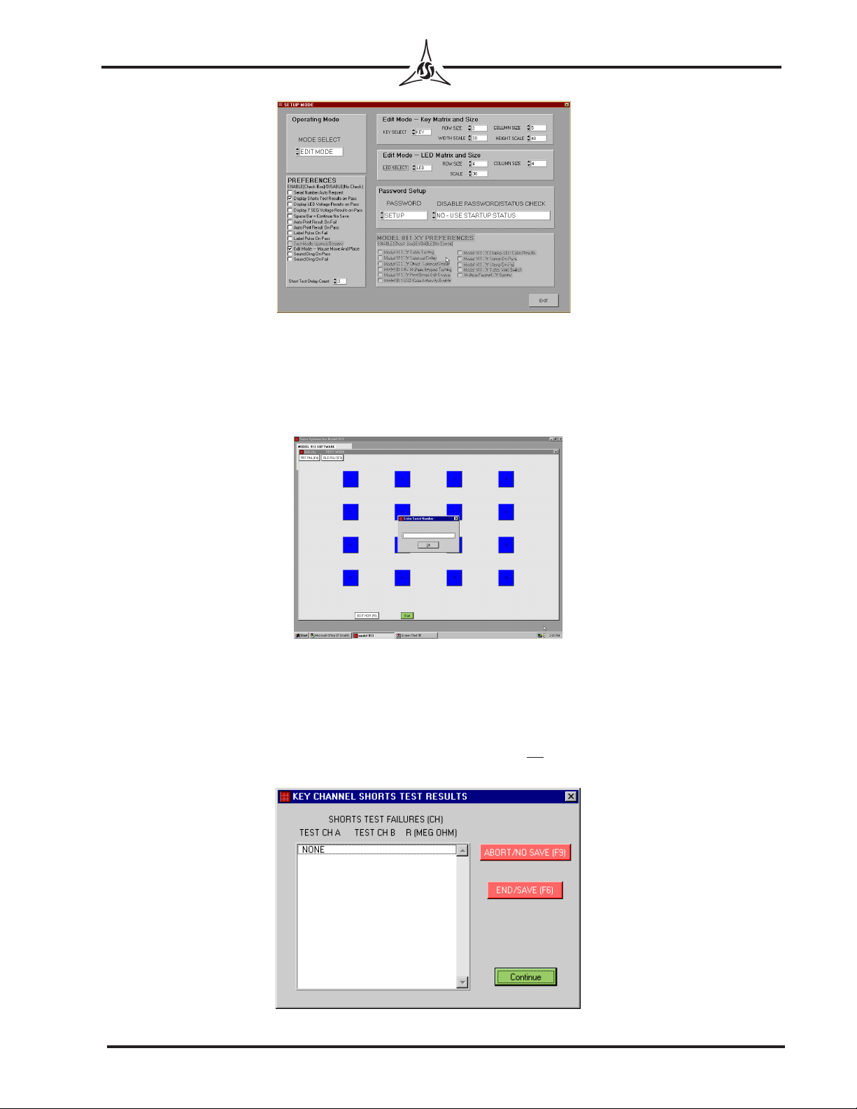
(Figure 3) will appear. To create configurations for the keys and LEDSthat you are about
to test, go to the Operating Mode box and select EDIT MODE in the MODE SELECT field. Go
to the Edit Mode-Key/LED Matrix and Size box. In the KEY/LED SEL field, select KEY. In
the ROW SIZE and COLUMN SIZE fields, select the configuration of the keypad you wish to
test using values from 1to 15. To create the sample keypad with a 4x4 matrix, select a
row size of 4and a column size of 4. Set the WIDTH SCALE and HEIGHT SCALE values to 50.
This is a good starting point. The width and height scales determine what size the keys
will be in relation to the overall display size.
- 4 -
TRICOR Systems Inc.
Preferences in SETUP MODE Window
1. Serial Number Auto Request: When enabled, before each keypad is tested a
request for Enter Serial Number will be displayed (Figure 4). An operator may
type a serial number, or a wedge bar code reader may be used.
2. Display Shorts Test Results on Pass (Default): If shorts test passes and this
preference is enabled, the KEY CHANNEL SHORTS TEST RESULTS screen
will be displayed. The operator will be required to continue (Figure 5). If disabled
and shorts test passes screen will not be observed and no operator action required.
This screen will always be displayed if shorts test fails.
Figure 5
Figure 4
Figure 3
- 5 -
TRICOR Systems Inc.
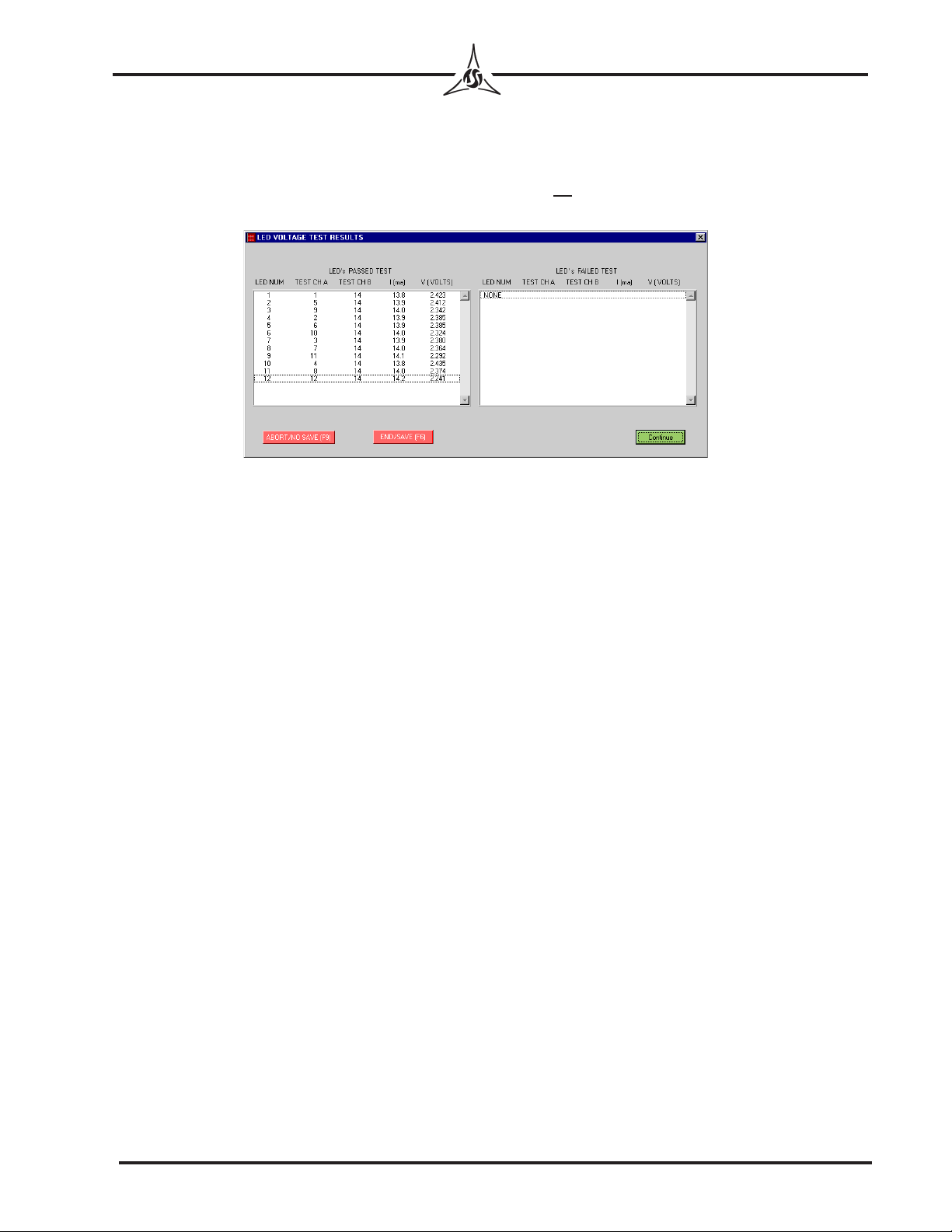
3. Display LED Voltage Results on Pass (Default): If LED Voltage test passes and
this preference is enabled, the LED VOLTAGE TEST RESULTS screen will be
displayed. The operator will be required to continue (Figure 6). If disabled and
shorts test passes screen will not be observed and no operator action required. The
screen will always be displayed if the LED test fails.
4. Display 7-SEG Voltage Results on Pass (Default): If 7-SEG Voltage test passes
and this preference is enabled, the 7-SEGMENT VOLTAGE TEST RESULTS
screen will be displayed. The operator will be required to continue. The screen will
always be displayed if the 7-SEG test fails.
5. Space Bar = Continue No Save: Enabling this function does not save data to a
file.
6. Auto Print Result On Fail: This will automatically print the test result for the last
keypad tested if it fails. The result will be in same format as Figure 41.
7. Auto Print Result On Pass: This will automatically print the test result for the last
keypad tested if it passes. The result will be in same format as Figure 41.
8. Label Pulse On Fail: This will send a pulse to an external printer (labels) when the
last keypad tested fails. Consult TRICOR for details.
9. Label Pulse On Pass: This will send a pulse to an external printer (labels) when the
last keypad tested passes. Consult TRICOR for details.
10. Test Mode Spanish Screens:This needs to programmed at TRICOR and is NOT
available unless specifically purchased. Consult TRICOR for details.
11. Edit Mode— Mouse Move And Place: This is the same as drag and drop. It allows
grabbing and dragging a Key, Led or 7-segment and placing in a specific position
during the edit mode. Leave enabled.
Figure 6

- 6 -
TRICOR Systems Inc.
12. Sound Ding On Pass: This will make a sound when a keypad passes all tests. This
is a wave file and the user may change the sound. Filename is 913pass.wav.
13. Sound Ding On Fail: This will make a sound when a keypad fails any test. This is
a wave file and the user may change the sound. Filename is 913fail.wav.
14. Short Test Delay Count: Is dependent on CPU speed and type of PC set as fol-
lows:
233 –350 MHz Short Test Delay Count “1”
350 – 450 MHz Short Test Delay Count “2”
450 – 550 MHz Short Test Delay Count “3”
550 – 700 MHz Short Test Delay Count “4”
700 – 900 MHz Short Test Delay Count “5”
900 – 1100 MHz Short Test Delay Count “6”
Please note if shorts test fail on known good samples or several samples tested
increase Count number by 1.
15. Model 911 XY Preferences:Not available unless 911 is purchased.
EDIT MODE
Altering Keypad Appearance
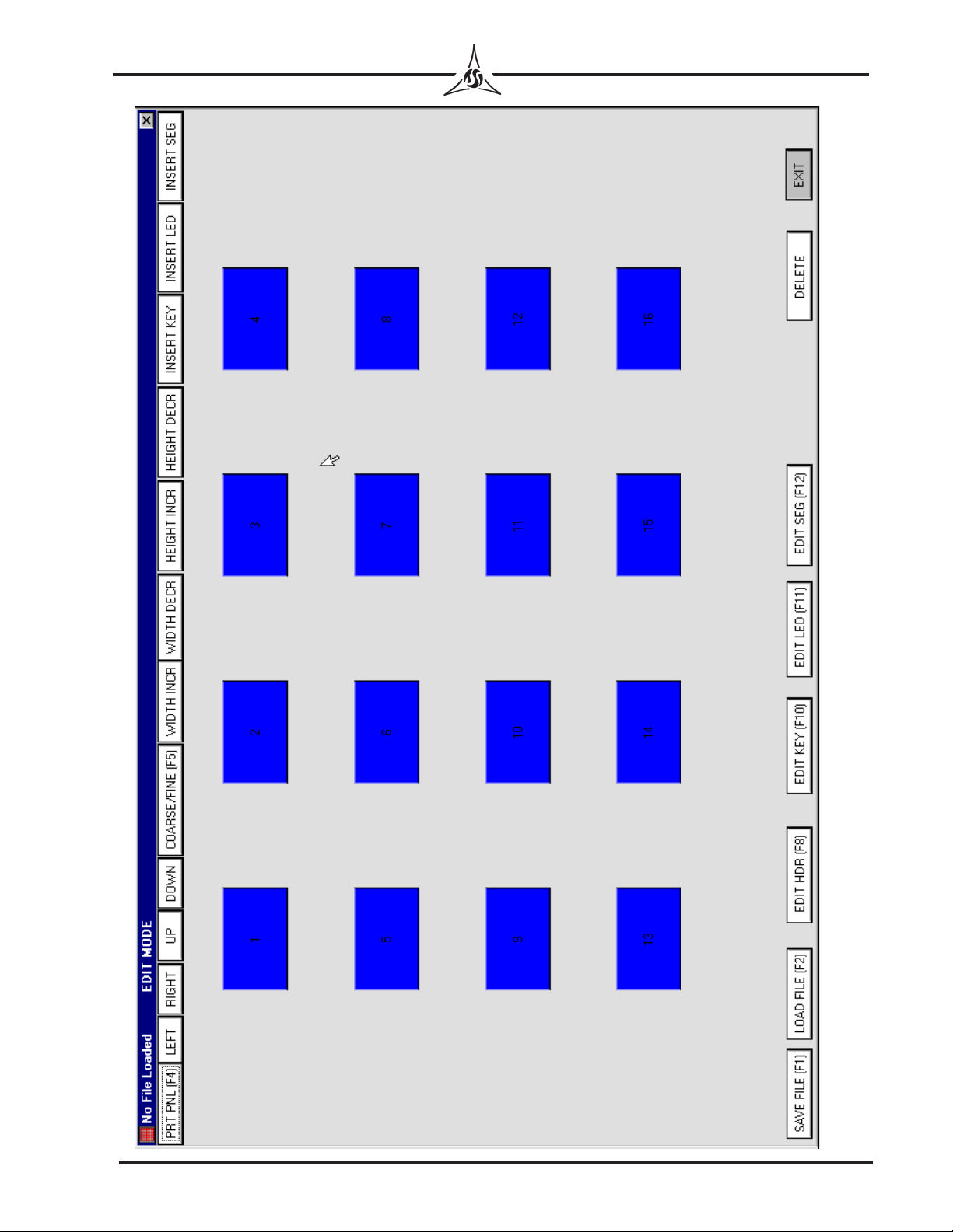
In the TRICOR Model 913 program window, open the “KEY TEST” window (Figure 7)
by clicking the green Start button. The “KEY TEST” window will appear with the 4x4
matrix you generated earlier in this sample exercise.
Figure 7

- 7 -
TRICOR Systems Inc.
You may alter the appearance of the keypad on the screen. Each key, when selected by
clicking on it, can be moved or altered independently by using the buttons at the top of
the window.
LEFT, RIGHT, UP, or DOWN will move the selected key left, right, up, or down re-
spectively. COARSE/FINE (F5), to move the key in large or small increments of
space.
WIDTH INCR, WIDTH DECR, HEIGHT INCR, and HEIGHT DECR will adjust the dimen-
sions of the individual keys.
INSERT KEY will add a key to the layout. The new key will insert in the top left-
hand corner of the screen. Click on the new key and alter or reposition it in the
same manner as the others.
INSERT LED and INSERT SEG will add LEDs and 7-Segment Displays, respectively.
These may be manipulated in the same manner as new keys.
DELETE will delete a selected key, LED or SEG from the layout.
In EDIT MODE a quicker way to alter appearance of the keypad screen is to use the
following keys on the PC keyboard:
Key(s) Command Button Function
Insert (Ins) INSERT KEY
Ctrl Ins INSERT LED
Ctrl Shift Ins INSERT SEG
←LEFT
→RIGHT
↑UP
↓DOWN
Shift ←WIDTH DECR
Shift →WIDTH INCR
Shift ↓HEIGHT DECR
Shift ↑HEIGHT INCR
Delete (Del) DELETE
Escape (Esc) EXIT
F1 SAVE FILE
F2 LOAD FILE
F4 PRT PNL (Print Panel)
F5 COARSE/FINE
F8 EDIT HDR (Edit Header)
F10 EDIT KEY
F11 EDIT LED
F12 EDIT KEY

- 8 -
TRICOR Systems Inc.
Use buttons at the lower edge of the screen for the following functions:
SAVE FILE(F1) to open the Save Test Configuration Data dialog box. Files should
be saved with the extension “.cfg”. (Figure 8)
LOAD FILE(F2) to open the Load Test Configuration Data dialog box. (Figure 9)
Figure 8
Figure 9
- 9 -
TRICOR Systems Inc.
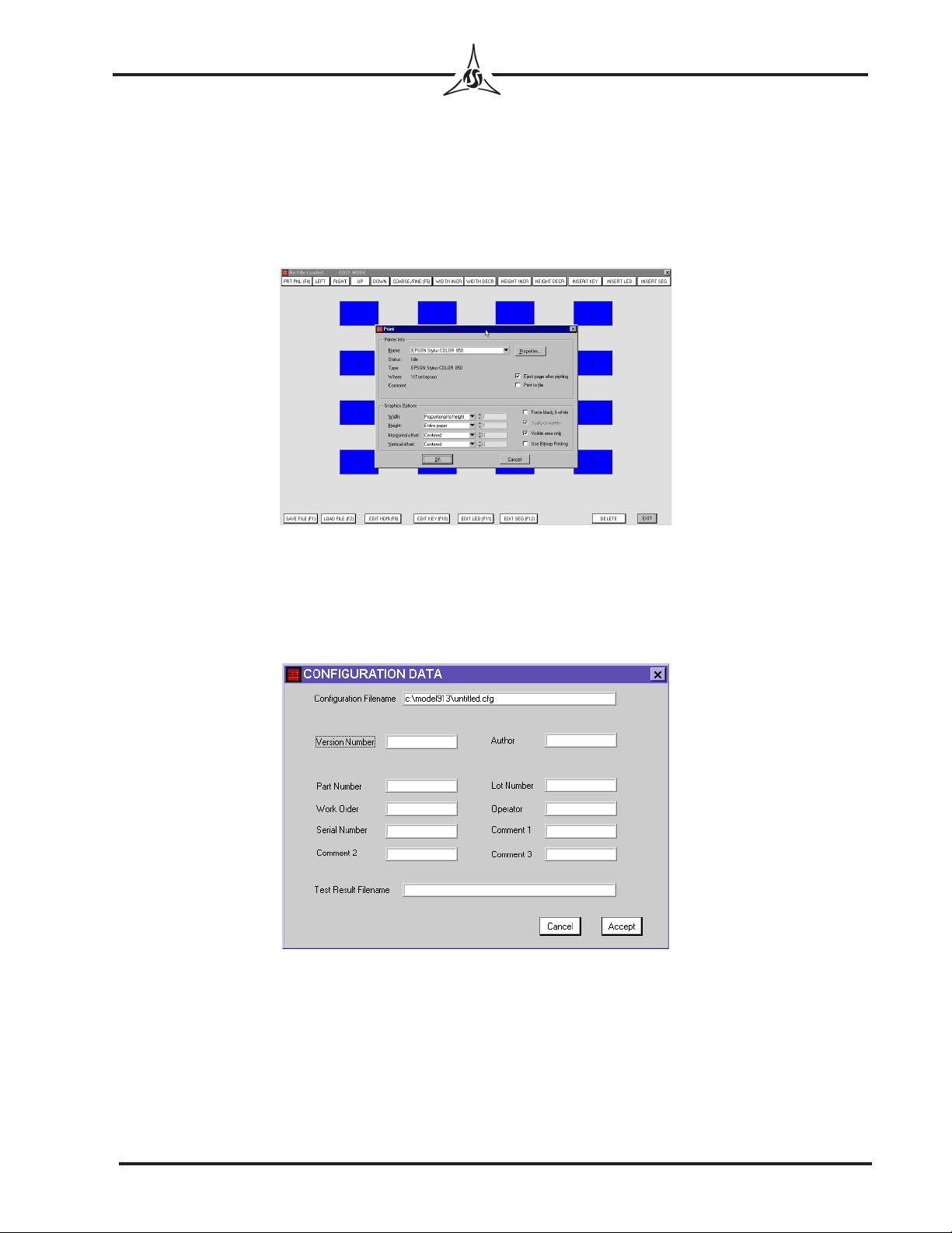
PRT PNL (F4) to open the Print dialog box. (Figure 10) The file will print in color
unless your printer is set to print in gray scale or does not have color capabilities.
PRT PNL (F4) is available for use in the EDIT, LEARN and TEST modes. A
sample panel printout is shown as figure 11 (page 9). If PRT PNL (F4) is selected
in TEST MODE after a test has been run, the resistance values for the keys tested
will appear in the center of the keys in lieu of the key numbers.
EDIT HDR(F8) (Edit Header) to open the CONFIGURATION DATA dialog box.
(Figure 12)
Figure 10
Figure 12
- 10 -
TRICOR Systems Inc.
Figure 11
- 11 -
TRICOR Systems Inc.
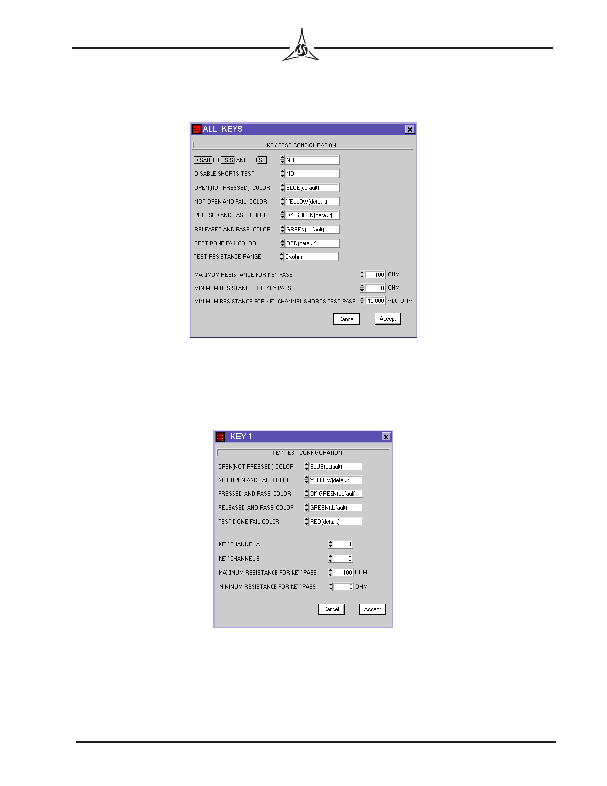
EDIT KEY(F10) to open ALL KEYS dialog box and presents key test configuration
setting options. You may either keep the defaults, or choose from the available
options. This dialog box contains the following fields: (Figure 13)
Edit individual key: Place cursor on key desired then right click. You may then change
setting for tolerances, colors, and channels. NOTE: Channel 0 will be listed if key has
not been learned. The dialog box contains the following fields: (Figure 14)
Figure 13
Figure 14
- 12 -
TRICOR Systems Inc.
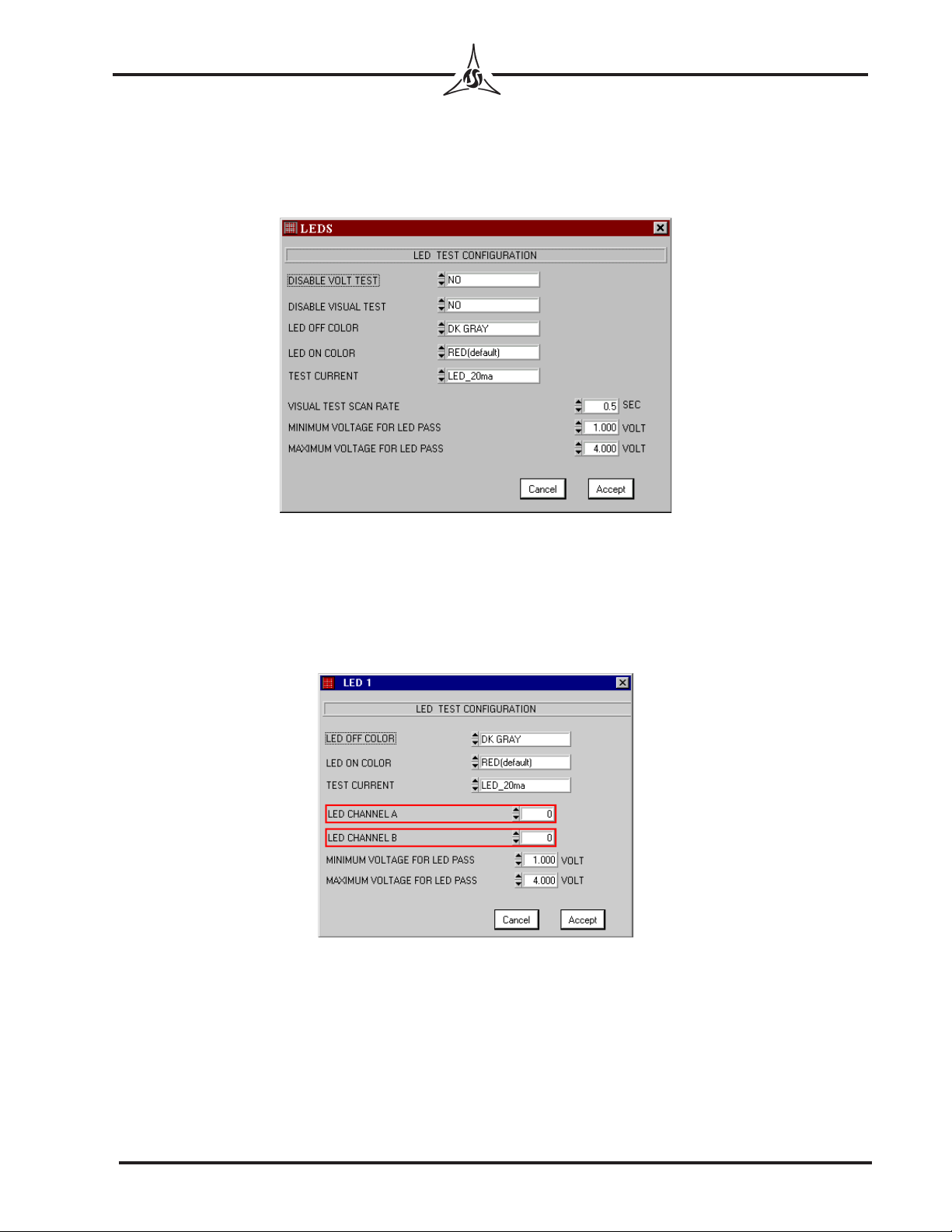
EDIT LED(F11) to open LEDs dialog box and presents LED TEST CONFIGURATION
setting options. You may either keep the defaults, or choose from the available
options. In the VISUAL TEST SCAN RATE field, enter a value from .2 to 60 seconds
(Figure 15).
Edit individual LEDs: Place cursor on LED desired then right click. You may then
change setting for tolerances, colors, current, and channels. NOTE: Channel 0 will be
listed if LED has not been learned. The dialog box contains the following fields:
(Figure 16)
Figure 15
Figure 16

- 13 -
TRICOR Systems Inc.
EDIT SEG(F12) to open 7 SEGMENTS dialog box and presents 7-segment test
configuration setting options. You may either keep the defaults, or choose from
the available options (Figure 17).
Edit individual 7-Segment: Place cursor on 7-segment desired then right click. You
may then change setting for tolerances, colors, current, and channels. NOTE: Channel 0
will be listed if key has not been learned. The dialog box contains the following fields:
(Figure 18)
EXIT allows you to quit and return to the TRICOR Model 913 program window.
If you have not saved your file, a “Save Changes to File before Exiting?”
prompt will appear. Select Yes or No. If you do not save your changes to a file at
this point, all changes will be lost.
Figure 17
Figure 18
- 14 -
TRICOR Systems Inc.
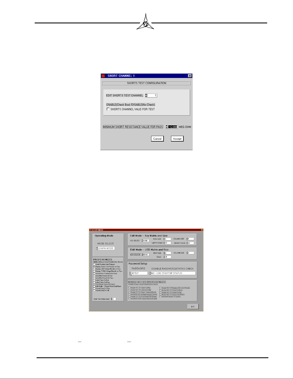
Edit Short Channels: To enable or disable individual shorts channels on a test screen
double click left button in the gray area of the window. Note: channels may already be
enabled if Learn Mode was completed. The dialog box contains the following fields.
(Figure 19) The operator may set a minimum short resistance value (from 1,000 ohms to
12 Megohms) for each channel. The default value is 12.000 Megohms.
To continue with the sample exercise, save this file with the filename “Test.cfg” and close
the key test window. This will return you to the TRICOR Model 913 program window.
LEARN MODE
Entering Learn Mode
In the TRICOR Model 913 program window, click on SETUP.Go to the Operating
Mode box and select LEARN MODE in the MODE SELECT field. (Figure 20) It does not matter
which setting in the KEY/LED SEL field is used. Exit SETUP MODE and click on the green
Start button in the TRICOR Model 913 program window. Click LOAD FILE(F2) and type
Test in the Filename field. Click on Load to bring up the 4x4 sample matrix. KEY TEST is
now open in LEARN MODE.
Figure 19
Figure 20
Table of contents


