Trimax Warlord 3 Series User manual

1
SPARE PARTS
INSTRUCTIONS # 51
Date Created: 31/05/2017
Product: Warlord S3
Title: Rotor Removal and Replacement
SAFETY! Before attempting to make any adjustments or carry out maintenance on the mower, review
the hazard identification table (section 3a of your Operator Manual) and take all necessary precautions.
Due to the specialized nature of Rotor removal and replacement, it is recommended that this procedure is
only attempted at a fully equipped General Engineering Workshop.
Read through this entire process prior to starting. Take note of where parts are removed from!
Ensure all appropriate protective equipment is used.
Heavy Lifting Equipment is required for this process, ensure all Lifting Equipment is suitably rated!
REQURIED SHIM THICKNESS
Warlord Series 3 Mowers:
0.45 –0.5mm (0.018 –0.020”) thick.
IMPORTANT:
Two strips of shim material are required for this
operation.
These should be a little longer than one side of the
square rotor bearing housing and about 10-15mm
(3/8 - 5/8”) wide.
Use the Tractor hydraulics to position the
Headstock CENTRALLY in relation to the
Mower.
Disconnect the Warlord S3 and P.T.O Shaft from
the Tractor.
Remove the P.T.O Shaft from the Warlord S3.
This is detailed in the Operators Manual for the
Mower.
IMPORTANT:
A Warlord S3 175 Right-Hand Offset is shown
opposite, however this process applies for ALL
models and sizes.
The end with the Pulleys is ALWAYS referred to
as the DRIVE END. If your Warlord S3 is a
Left-Hand offset, the drive end will be
OPPOSITE to what is shown. However, the
process is IDENTICAL!
DRIVE END
2
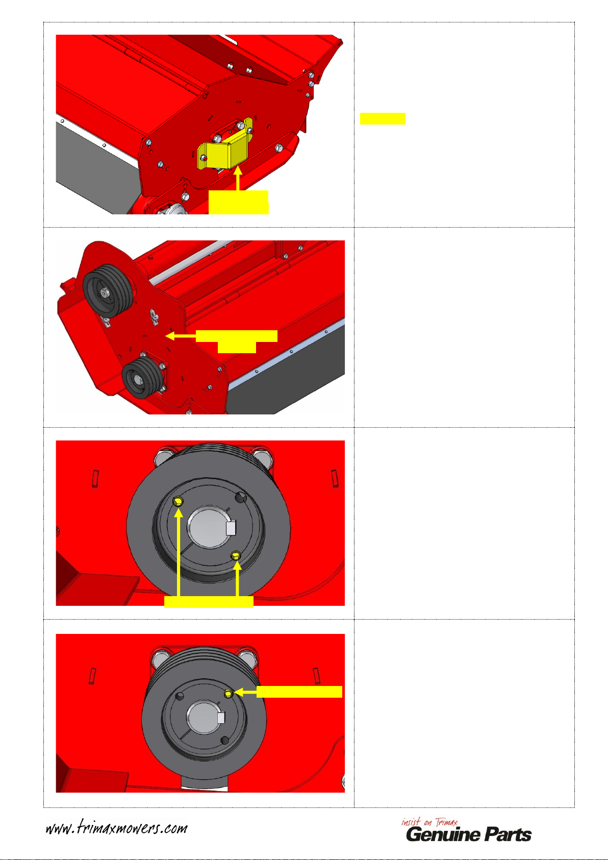
Remove the Rotor Bearing Guard from the
NON-DRIVE end of the Mower as shown in
YELLOW.
Place the Rotor Bearing Guard and fasteners to
one side.
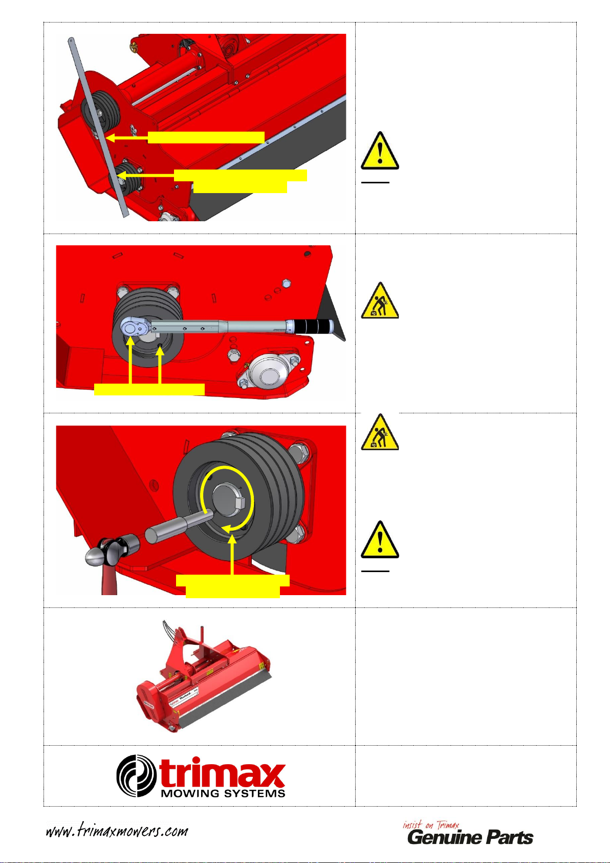
Remove the Belt Guard from the Drive-end of the
Mower as detailed in the Operators Manual.
Remove the Belts as detailed in the Operators
Manual.
At the Rotor Pulley, remove the two Grub Screws
shown.
Reinsert one Grub Screw into the unused hole in
the Pulley.
Gradually tighten this Grub Screw.
As it is tightened, the Pulley will contact the
Bearing Housing and then begin to drive the Taper
Lock Bush off the Rotor Stub.
Remove Belt Guard
and Belts
Remove Grub Screws
Reinsert Grub Screw
Remove Rotor
Bearing Guard

3
Once the Taper Lock Bush has been driven off as
far as possible, remove the Grub Screw.
Insert a Flat Bladed Screwdriver into the Slot
opposite the Removal Hole as shown.
Use this to lever the Taperlock Bush open slightly.
Slide the Taper Lock Bush off the Rotor Stub.
Note:
USE CAUTION, apply the absolute MINIMUM
amount of leverage to slide the Bush off!
If too much leverage is applied, the bush may
fracture through its thinnest point!
Remove the Rotor Pulley from the Rotor Stub.
Place the Rotor Pulley Components to one side.
Remove the Key from the Rotor Stub.
Sling the Mower around the Headstock Link Pin.
Lift the Mower until standing on its end as shown
in the RIGHT image.
Note:
Ensure that the Hydraulic Hoses are tucked away
so they do not get damaged!
Remove Grub Screw
Flat Bladed
Screwdriver in place
Pulley removed
Taper Lock Bush driven
as far as possible
Sling around Pin
Lift to this
position
Remove Key
4
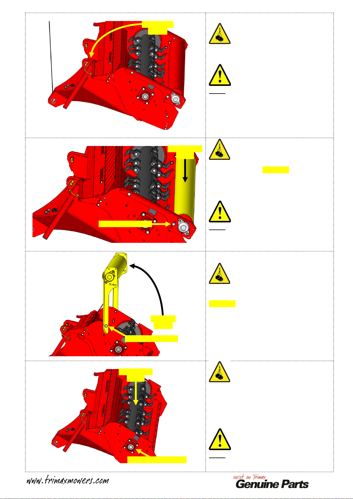
Lower the Mower back down so that the TOP of
the Headstock is now contacting the Ground and
the Rotor is facing UPWARDS as shown.
Note:
The Mower may require some assistance to move
past its tipping point.
USE EXTREME CAUTION DURING THIS
STEP!
Using suitable Lifting Equipment, support the
Rear Roller, shown in YELLOW.
Once supported, remove the two M16 x 35 Bolts
and M16 Nordloc Washers used to secure the
Trailing Arms to the Body near the Roller. One
side shown.
Note:
Take note of the hole position used near the
Roller, this will be needed to set the Mower back
to the same cut height later in this process!
Slacken the remaining two M16 x 35 Bolts.
Lift the Transport System to position as shown in
YELLOW.
Then, remove the two M16 x 35 Bolts and M16
Nordloc Washers.
One side shown.
Remove the entire Transport System and place to
one side with the fasteners.
Using suitable Lifting Equipment, support the
Rotor.
Once supported, remove the four M16 x 50 Bolts
and M16 Spring Washers from each of the Rotor
Bearings.
One side shown.
Note:
Take note of the Rotor Bearing Grease Nipple
direction!
Lower to this
position
Sling Roller to
support
Lift to this
position
Then remove this Bolt
Then remove this Bolt
Sling Rotor to
support
Then remove these Bolts

5
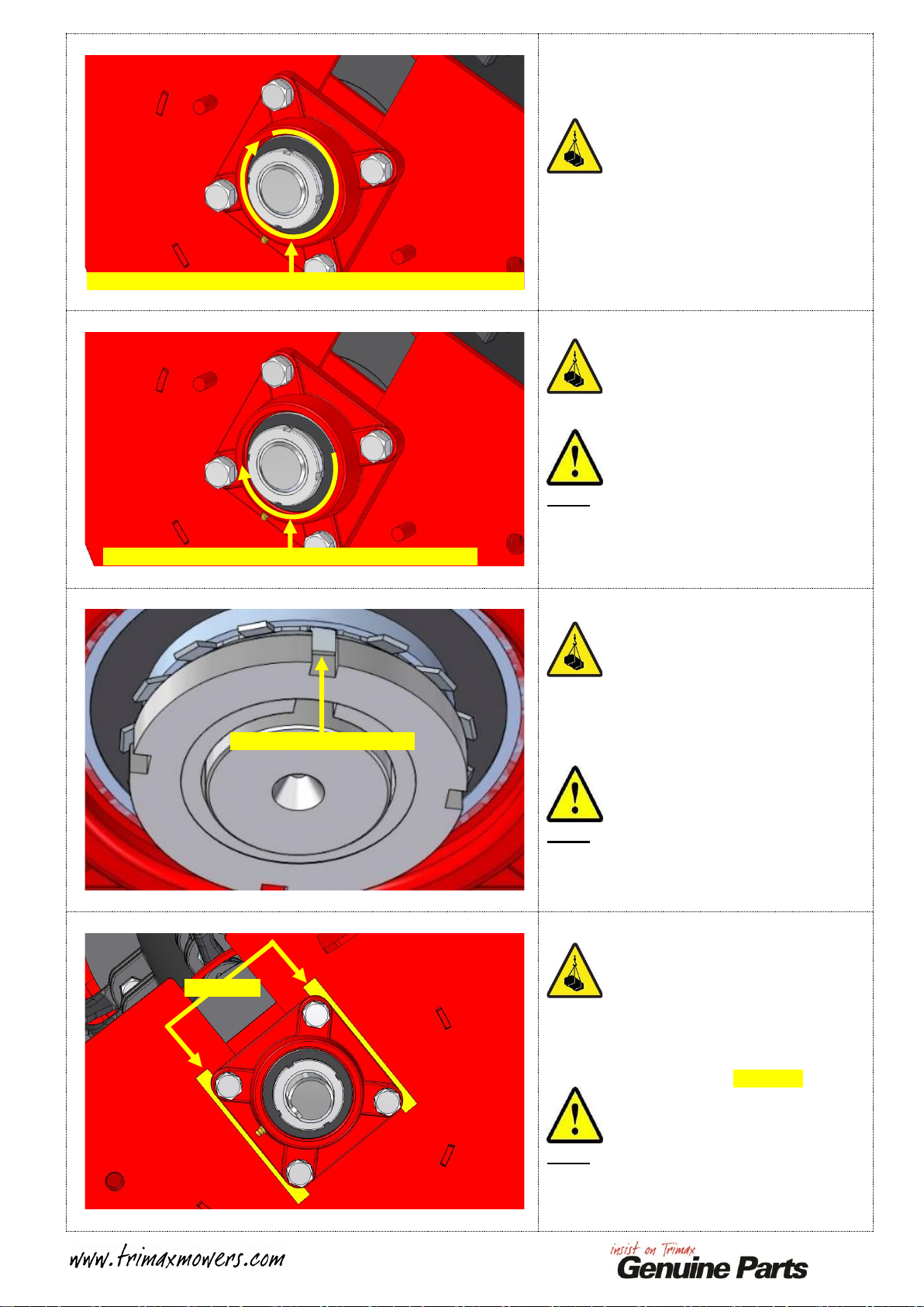
Slacken the Rotor Bearing Locking Nut shown.
DO NOT remove!
Use a suitable section of Tube as a Drift to drive
the Rotor Locking Nut and Taper Sleeve
INWARDS towards the Rotor. This will release
the Rotor Bearing from the Rotor Stub Shaft.
Note:
There is a Locking Tab for this Nut. This will need
to be bent out of the way!
Slide the Rotor Bearing off the Rotor Stub Shaft.
Place the Bearings and Fasteners to one side.
Repeat at the opposite end of the Mower to
remove the second Rotor Bearing.
Note:
If the Rotor Bearings require replacing, please see
you Spare Parts Listing for detail.
Remove the two Rotor Rings from between the
Body and the Rotor.
Place these to one side.
Using the Lifting Equipment, extract the Rotor
from the Body.
Place the damaged Rotor to one side.
Note:
Save any Flails that are in usable condition! These
can be used as spares when the Mower is back in
operation.
Slacken Locking Nut, then
drive INWARDS
Slide the Rotor Bearing
off Rotor Stub Shaft
Remove Rotor Rings
Remove Rotor

6
Collect the replacement Rotor using suitable
Lifting Equipment.
Clean the Rotor Stub Shafts and ALL Rotor
Bearing and Rotor Pulley Components using
White Spirits and a Clean Cloth to remove
contaminants.
IMPORTANT:
Position alongside the damaged Rotor.
Ensure that the LONG Rotor Stub Shafts are
BOTH facing the same direction.
Check that the Flails are facing the SAME
direction as the damaged Rotor!
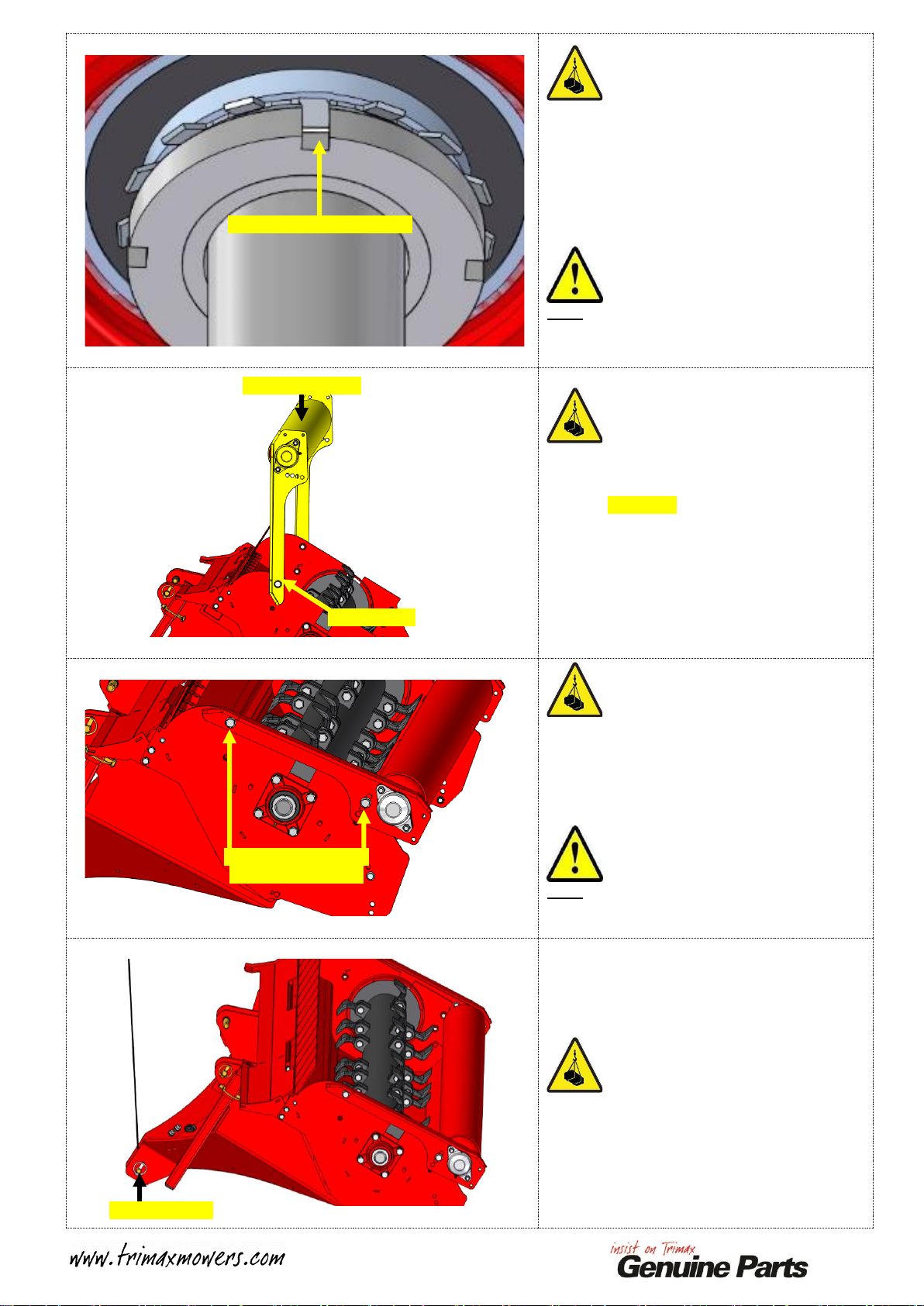
Prepare the Rotor Bearings for fitment.
Separate out the Taper Sleeve Assembly as shown.
Apply Copper Anti-Seize to the THREADS of the
Taper Sleeve.
Apply Copper Anti-Seize to the BEVELLED face
of the Locking Nut.
Insert the Taper Sleeve, thread first, into the
REAR of the Rotor Bearing as shown.
Fit the Locking Washer over the Taper Sleeve as
shown.
Align the Inner Tab with the slot in the Taper
Sleeve.
The Outer Tabs MUST face away from the Rotor
Bearing as shown.
Taper Sleeve
Locking Nut
Locking Washer
Locking Washer in place
Insert Taper Sleeve

7
Fit the Locking Nut to the Taper Sleeve.
The Bevelled face of the Locking Nut MUST face
TOWARDS the Rotor Bearing.
Wind the Locking Nut on a few turns. DO NOT
TIGHTEN!
Repeat the above Bearing fitment process for the
second Rotor Bearing Assembly.
Sling the replacement Rotor using suitable Lifting
Equipment.
Lift in to position over the Body.
Ensure that the LONG Rotor Stub is facing the
DRIVE-END of the Body.
Note:
The DRIVE END is the end of the mower with
Drive Pulleys!
Carefully lower the replacement Rotor into place
in the Body.
Leave the Lifting Equipment in place to support
the Rotor.
Note:
An assistant may be required to help guide the
Rotor into place.
Loosely fit the Rotor Rings back into place at each
end of the Body.
Ensure that the FLAT side of each Rotor Ring
faces AWAY from the Rotor.
Locking Nut in place
Rotor in place over Body
LONG Stub at
DRIVE END
Rotor lowered into Body
Refit Rotor Rings

8
Mount the NON-DRIVE END Rotor Bearing.
Ensure the Grease Nipple is facing in the right
direction before fitting the mounting bolts.
FULLY TIGHTEN THE MOUNTING BOLTS.
Ensure the fasteners are fitted as original!
Note:
A medium strength thread locker is required for
use on the mounting bolts.
The NON-DRIVE END is the end of the mower
with NO Drive Pulleys!
Mount the DRIVE END bearing housing, also
ensuring the Grease Nipple faces as originally
fitted!
HAND TIGHT ONLY AT THIS STAGE!
Ensure the fasteners are fitted as original!
Note:
A medium strength thread locker is required for
use on the mounting bolts.
The DRIVE END is the end of the mower with
Drive Pulleys!
Ensure the Rotor is CENTRALIZED.
The gap between the end of the Rotor and the
inside of the Endplate MUST be the same at
BOTH ends!
At the NON-DRIVE END insert a wedge or
similar means to prevent Rotor from shifting.
Insert a Pry Bar between the Locking Washer and
the Inner Race of the Rotor Bearing.
Carefully apply leverage to move the Taper Sleeve
OUTWARDS as far as possible.
IMPORTANT:
If the Rotor moves during this process,
re-centralize before proceeding!
Use caution to not damage the Bearing Seal!
NON-DRIVE END Bearing in place
FULLY tighten mounting bolts
DRIVE END Bearing in place,
DO NOT tighten mounting bolts
Centralize Rotor
Move the Taper Sleeve
OUTWARDS
Pry Bar
9
Hand tighten the NON-DRIVE END Locking Nut
as tight as possible so the Taper Sleeve begins to
lock onto the Rotor Shaft.
Use a suitable “C” spanner to tighten the Locking
Nut one half of a turn (180°)
Note:
If a “C” spanner is not available, tighten the
Locking Nut using a suitable pin punch and a light
hammer.
Align one of the slots in the Locking Nut with the
nearest tab on the Locking Washer.
Bend the tab into the slot in the Locking Nut to
secure.
Note:
It may be necessary to tighten the Locking Nut
slightly to achieve this.
Move to the DRIVE END.
Fit the strips of shim material to opposite sides of
the Bearing Housing between the Endplate and the
Bearing Housing as shown in YELLOW.
Note:
The details for the shim material are detailed on
PAGE 1.
Tab aligned and bent into slot
Hand tighten the NON-DRIVE END Locking Nut as tight as possible
Tighten the NON-DRIVE END Locking Nut a further 180°
Shims fitted

10
Slide the Bearing Assembly HARD up against the
shims.
DO NOT try to move the Bearing by tightening
the bearing housing mounting bolts!
If the Taper Sleeve locks up and prevents the
Bearing from moving inwards, loosen the Locking
Nut slightly and gently tap it inwards to release the
taper.
LEAVE THE MOUNTING BOLTS HAND
TIGHT ONLY AT THIS STAGE!
With the bearing housing remaining firmly pressed
against the shims, insert a Pry Bar between the
Locking Washer and the inner race of the DRIVE
END Rotor Bearing.
Carefully apply leverage to move the Taper Sleeve
OUTWARDS as far as possible.
Note:
Use caution to not damage the Bearing Seal!
Hand tighten the DRIVE END Locking Nut as
tight as possible so the Taper Sleeve begins to lock
onto the Rotor Shaft.
Remove the shims.
Use a suitable “C” spanner to tighten the
DRIVE END Locking Nut half of a turn (180°)
As the Locking Nut is tightened the Bearing
Housing should gradually move towards the
mower endplate until there is no gap when the
Locking Nut is fully tightened.
Note:
If a “C” spanner is not available, tighten the
Locking Nut using a suitable pin punch and a light
hammer.
Push DRIVE END Bearing
HARD against shims
Pry Bar
Move Taper Sleeve
OUTWARDS
Hand tighten Locking Nut,
then remove shims
Tighten a further 180°
11
Align one of the slots in the Locking Nut with the
nearest tab on the Locking Washer.
It may be necessary to tighten the Locking Nut
slightly to achieve this.
Bend the tab into the slot in the Nut to secure it.
FULLY TIGHTEN THE DRIVE END
MOUNTING BOLTS.
Ensure the fasteners are fitted as original!
Note:
A medium strength thread locker is recommended
for use on the mounting bolts.
Sling the Rear Roller as before.
Lift the Transport System back into place as
shown in YELLOW.
Secure the FRONT to positions using two
M16 x 35 Bolts and M16 Nordloc Washers.
Hand tight ONLY at this stage!
One side shown.
Lower the Transport System into its original
position. Align the holes in the Trailing Arms with
the Body.
Refit the remaining M16 x 35 Bolts and M16
Nordloc Washers. Torque ALL four M16 x 35
Bolts to 185Nm (137ft/lbs)
Note:
This torque figure is critical to ensure the
Transport System is secured correctly to the Body!
As before, sling the Mower around the Headstock
Link Pin.
Tab aligned and bent into slot
Lift to this position
Refit this Bolt
Torque M16 x 35 Bolts
to 185Nm (137ft/lbs)
Sling around Pin

12
Lift the Mower until standing on its end.
Lower the Mower back down so that the
Headstock is facing UPWARDS as shown on the
RIGHT.
Note:
The Mower may require some assistance to move
past its tipping point.
USE EXTREME CAUTION DURING THIS
STEP!
Refit the Bearing Guard to the NON-DRIVE End
of the Mower as shown in YELLOW.
Secure using the M12 Spring Washers and M12
Plain Nuts.
Fully tighten.
Refit the Key to the Keyway in the DRIVE END
of the Rotor Shaft.
Note:
High Strength Retaining Compound is
reccomended to secure the key!
Apply Medium Strength Thread Locking
Compound to each of the Grub Screws.
Insert the Taper Lock Bush (402-060-710) into the
Gearbox Extension Pulley (403-361-270)
Align the holes as shown.
Fit the Grub Screws loosely using the Holes
shown.
Note:
DO NOT place a Grub Screw in the location
highlighted RED, this is only used for pulley
removal!
Reinsert Grub Screws into
Gearbox Extension Pulley
Lift to this
position
Lower to this
position
Refit the Bearing Guard
Refit the Key

13
Adjust the position of the Extension Shaft Adjuster
so that the Extension Shaft is running
PARALLEL with the Mower Body.
Note:
It is CRITICAL that the Extension Shaft is
PARALLEL to the Body when fitting the Pulleys!
This is to ensure the correct alignment of BOTH
the Rotor and Gearbox Extension Pulleys!
IMPORTANT:
There are TWO types of Rotor Pulley used on
Warlord.
•The TYPE 2 Rotor Pulley has a FLAT back
side.
•The TYPE 4 Rotor Pulley has a RECESSED
back side.
Inspect your Rotor pulley and determine which
type you have.
The positioning of these two types of Rotor
Pulleys is slightly different, however the securing
process is identical!
See below for positioning details for each type.
Flat Back - Type 2 Pulley Position
Align the keyway in the Taper Lock Bush with the
Key fitted to the Rotor Stub.
Slide/lightly tap the Rotor Pulley onto the Rotor
Stub until the back of the Pulley is against the
Rotor Bearing Locking Nut as shown opposite.
Note:
There are TWO types of Rotor Pulley used on
Warlord, see above for detail.
Recessed Back - Type 4 Pulley Position
Align the keyway in the Taper Lock Bush with the
Key fitted to the Rotor Stub.
Slide/lightly tap the Rotor Pulley onto the Rotor
Stub until the back of the Pulley is just over the
edge of the Rotor Bearing Housing as shown
opposite.
Note:
There are TWO types of Rotor Pulley used on
Warlord, see above for detail.
Rotor Pulley contacting
Rotor Bearing Locking Nut
Rotor Pulley just over Rotor
Bearing Housing
Set Extension Shaft
PARALLEL
Extension Shaft Adjuster
14
Check the Pulley alignment using a
Long Straight Edge from the Extension Shaft
Pulley. Ensure that the Straight Edge is positioned
as shown opposite.
Adjust the position of the Rotor Pulley so it is
approximately 1mm (1/16”) INWARDS from the
Straight Edge.
Very lightly nip up the Grub Screws.
Note:
The Rotor Pulley will pull OUTWARDS when
tightened! It is CRITICAL these Pulleys are
aligned correctly, otherwise premature Drive
failure may occur!
Using a Hex Socket and a Torque Wrench, tighten
the Grub Screws gradually and alternately.
Torque the Grub Screws to 50Nm (39ft/lbs)
Using a Hammer and a suitible Drift, tap around
the Taper Lock Bush.
Re-torque the Grub Screws to 50Nm (39ft/lbs)
REPEAT THIS STEP THREE TIMES.
Note:
This will ensure that the Taper Lock Bush is
seated square in the taper bore of the Rotor Pulley
and is secured correctly!
Grease the Rotor Bearings as detailed in your
Operator Manual.
Fit and tension the Drive Belts as detailed in your
Operator Manual.
Fit the Belt Guard as detailed in your Operator
Manual.
This Fitment process is now complete.
Straight Edge across Pulleys
Set in 1mm (1/16”) INWARDS
from the Straight Edge
Tap around Bush, re-torque
to 50Nm (39ft/lbs) x 3
Torque to 50Nm (39ft/lbs)
This manual suits for next models
1
Other Trimax Lawn Mower manuals


