Triton T550i User manual

Installers please note these InstructIons are to be left wIth the user
2180149I February 2009
Installation and
operating instructions
T550i power shower pump

T550i
CONTENTS Page
Plumbing and electrical notes...................... 1
Introduction ................................................ 2
Safety warnings ........................................... 2
Key to main components ............................3
Water requirements ..................................... 4
Electrical requirements................................. 5
Siting of the pump ......................................5
Installation...................................................6
Variable speed control ................................. 9
Commissioning............................................ 9
Spare parts ................................................. 11
Fault finding ............................................... 12
Guarantee, Service Policy, Etc. ..............Rear cover
To check the product suitability for commercial and multiple installations, please contact Triton’s
specification advisory service before installation.
Telephone:
Facsimile:
E mail:
0844 980 0730
0844 980 0744

T550i
1
1 PLUMBING NOTES
1.1 All installations must comply with Water
Regulations/Byelaws.
1.2 Supply pipes must be flushed thoroughly
to clear debris before connecting to the
pump and shower.
1.3 DO NOT connect the pump unit to the
mains cold water supply as it would
damage the unit and also, the installation
would be in breach of the guidance notes
contained in ‘1’ above.
1.4 DO NOT use excessive force when making
connections to the flexible connector hoses.
1.5 DO NOT turn on the electrical supply to
the pump until the plumbing connections
and commissioning procedure have been
completed. The pump must not be
operated dry without water.
1.6 DO NOT solder pipes or fittings within
300mm of the pump, as heat transfer can
damage the components.
1.7 A dedicated cold water supply must be
taken directly from the cold water cistern
to the pump. This draw-off must be on
the opposite side of the cistern to the float
operated valve.
1.8 The action of the pump is to increase the
flow rate. If the supply pipework cannot
handle the resulting flow rate then:
1.8.1 The anticipated flow rate may not
be achieved.
1.8.2 Air may be drawn into the hot
supply from the vent pipe causing
spluttering and temperature fluctuations at
the sprayhead.
1.9 A high level hot feed pipe run must not rise
above the level of water in the cistern. To
reduce the risk of air locks pipes should be run
level with or below the base of the cistern.
1.10 Standard gate valves or full way lever
valves MUST be fitted on the hot and
cold water supplies to the pump as an
independent means of isolating the water
supplies should maintenance or servicing
be necessary.
DO NOT use stop taps or ball-o-fix type
valves which restrict flow.
1.11 If the pump unit is installed on a common
supply which feeds an adjacent tap, the
maximum static inlet pressure for the
unit will, under certain circumstances be
exceeded. The action of closing the tap
can cause a pulse in the supply pressure
which may result in damage to the unit.
This can be resolved by the installation
of a suitably sized mini expansion vessel,
sited as close as possible to the tap and
pressurised to 50kPa (0.5 bar).
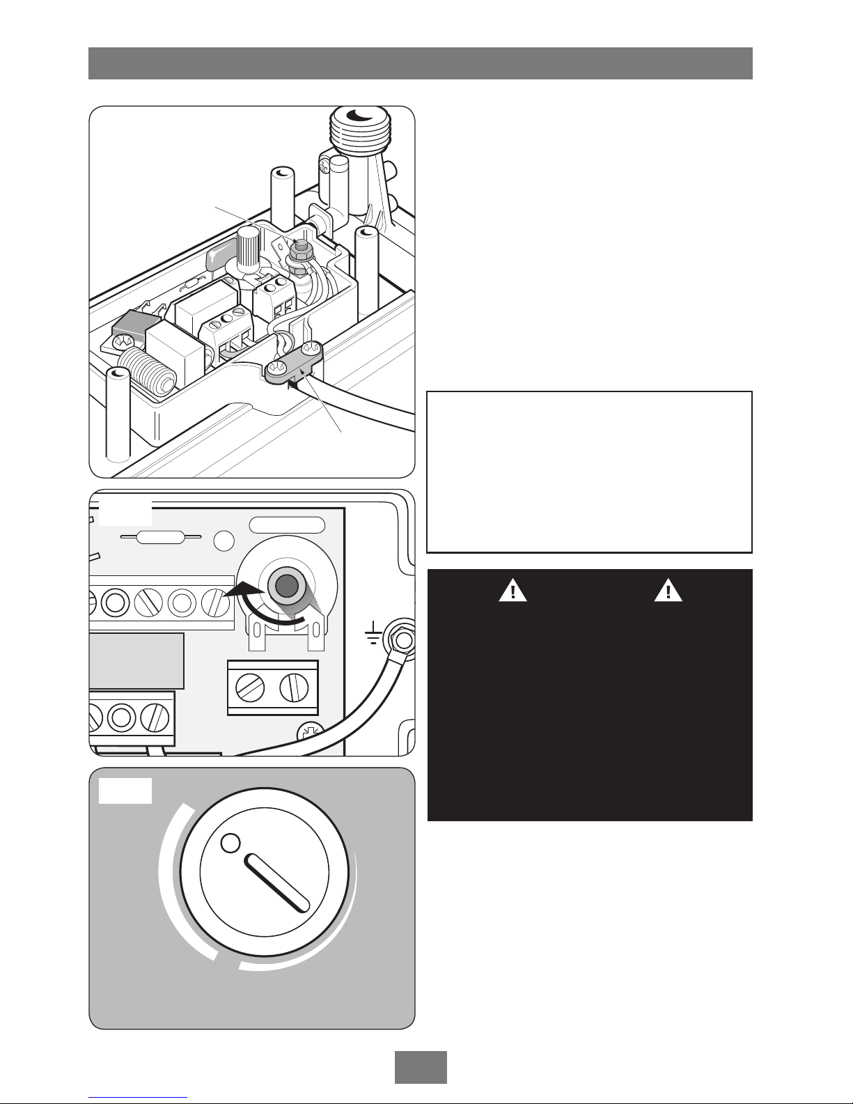
2ELECTRICAL NOTES
2.1 The installation must comply with BS 7671
‘Requirements for electrical installations’
(IEE wiring regulations). Ensure the
incoming hot and cold water supplies to
the pump are adequately earth bonded.
2.2 DO NOT turn on the electrical supply to
the pump until the plumbing connections
have been completed. The pump must
not be operated dry without water.
2.3 The mains supply must be 230-240V, at
50Hz, connected to the pump via a double
pole switched 3 Amp fused connection
unit (not supplied) with a minimum 3mm
contact separation gap in each pole.
2.4 In accordance with ‘The Plugs and Sockets
etc. (Safety) Regulations 1994’, the pump
is intended to be permanently connected
to the fixed electrical wiring of the mains
system.
2.5 To enhance electrical safety a 30mA
residual current device (RCD) should be
installed in all UK electric and pumped
shower circuits. This may be part of the
consumer unit or a separate unit.
Replacement parts can be ordered from Triton
Customer Service. See ‘spare parts’ for details.

T550i
2
INTRODUCTION
This book contains all the necessary fitting
and operating instructions for your Triton twin
impeller power shower pump. Please read them
carefully.
This product is rated at:
15 minutes on / 60 minutes off.
Care taken during the installation will ensure a
long and trouble free life from your unit.
IMPORTANT: All plumbing connections must
be completed before making the electrical
connections.
Please read through the whole of this book
before beginning your installation.
SAFETY WARNINGS
a. Under no circumstances must this pump
be connected to a mains cold water
supply. Failure to comply will invalidate the
guarantee.
b. The shower pump MUST NOT be used if
suspected of being frozen.
c. The pump must be earthed.
d. Switch off immediately at isolating switch if
water ceases to flow during use.
e. DO NOT operate the unit outside the
guidelines laid out in “site requirements”.
f. This pump is to be used for providing water
to a shower only.
In the interest of electrical safety a 30mA
residual current device (RCD) should be
installed in all UK electric and pumped
shower circuits. This may be part of the
consumer unit or a separate unit.

T550i
3
KEY TO MAIN COMPONENTS
Pump (fig.1)
1Inlet connector hose
2Outlet connector hose
3Integral flow switch
4Variable speed control
5PCB cover
Fig.1
1
1
2
2
3
5
4
3

T550i
4
WATER REQUIREMENTS
The installation must be in accordance with
Water Regulations and Byelaws.
For correct operation of this shower pump in
addition to the shower unit, water must be
gravity fed at nominally equal pressures directly
from the same cold water storage cistern (the
hot water being fed to the pump via the hot
water cylinder).
The cold water cistern and hot water cylinder
must each have a minimum capacity of 114
litres (25 galls). It is advisable to check that the
infill rate from the float operated valve meets
the output requirements. If the cistern supplies
water to a number of cold outlets it is advisable
to increase the stored water capacity to 230
litres (50 galls).
Both hot and cold water supplies to the pump
must be direct and not significantly affected by
any other outlets or connections.
(Fig.2) shows a recommended installation
where the hot water supply for the shower is
made via a tee connection on the underside of
the rising horizontal section of pipework from
the cylinder. Alternatively, the connection can be
taken from the hot supply pipe to other outlets
as long as it is the first draw-off below the
ventilation pipe tee.
THE PUMP MUST NOT BE CONNECTED TO THE
MAINS COLD WATER SUPPLY.
DO NOT connect into the rising vent pipework.
The pump must be positioned below the cold
water cistern and not placed in areas where it
will be subject to freezing conditions.
To ensure correct operation of the flow switches,
all pipework must be below the cold water cistern
and the sprayhead must be at least 150mm
below the bottom of the cold water cistern.
In situations where this requirement cannot be
met, contact Triton Customer Service for advice.
If used with a combination cylinder, the cold
water cistern must have a capacity of at least
114 litres (25 galls) to avoid starvation of water
to the pump, and a minimum head of water of
150 mm.
DO NOT use jointing compounds on any pipe
fittings.
Fig.2 Diagrammatic view (not to scale)
WARNING!
THIS PUMP IS DESIGNED TO SUPPLY
WATER TO A SHOWER ONLY.
Isolating
valve
Isolating
valves
Isolating
valve Cold
supply
Hot
supply
Alternative
connection
Vent
pipe tee
Mixer
valve
Cold
water
mains
supply
Hot water
cylinder
150mm
(6ins) min.
Drain
valve Pump
Other
hot water
draw offs
Isolating switch
or pull cord
switch (both
fused at 3A)
Cold
water
cistern
Ring main
Max Head 100kPa (10m)
Min Head 1.5kPa (0.15m)
Max Total Head 30m

T550i
5
ELECTRICAL REQUIREMENTS
The pump must be connected to a 230 – 240V
A.C. electrical supply, via a double pole switch
with at least 3mm contact separation. This can
be a ceiling mounted pull cord switch in the
shower room, or a wall mounted switch in an
adjacent room.
The pump installation should be fused at 3
amps.
It is recommended that a suitable residual
current device (RCD) is fitted in the electricity
supply circuit to this appliance.
Note: The installation and wiring must comply
with current IEE regulations.
When installed in any room containing a fixed
bath or shower, the pump MUST be located and
concealed inside a suitable cupboard, built-in
unit or other enclosure, in order so the pump
cannot be sprayed with water, and such that
a person using a fixed bath or shower cannot
touch the pump without using tools.
WARNING!
THE PUMP MUST BE EARTHED.
SITING OF THE PUMP
The pump MUST ALWAYS be positioned
BELOW the cold water cistern and be situated
as close as possible to the hot water cylinder.
It is recommended that the cold water supply
is taken from the opposite side of the cistern
to the float operated valve to prevent air
entrapment in the supply.
Position the pump in a dry area and ensure it is
accessible for any maintenance etc. that may be
necessary.
IMPORTANT: Ensure the ventilation slots on
the underside of the pump are free from
obstructions.
The hot water supply MUST NOT exceed 65°C
(149°F).
WARNING!
THE UNIT MUST NOT BE POSITIONED
WHERE IT WILL BE SUBJECT TO FREEZING
CONDITIONS.

T550i
6
Filter
Fig.4
INSTALLATION
Before commencing installation of the pump,
ensure the site conditions have been complied
with fully.
Also note the following:
• Pipework to precede wiring.
• The pump must be positioned in a dry area,
ideally in the linen/airing cupboard. It must be
well ventilated and not covered with towels
and sheets etc.
• Do not use with a combination water tank
system unless the cold water storage tank has
capacity of 114 litres (25 galls) or more.
• To assist in clearing air bubbles from the
system avoid using sharp bends where
possible. Flexible/swept fittings or formed
pipework is recommended.
• Ensure that all water supplies are isolated
before connection. Gate valves or full way
lever valves must be fitted immediately prior
to the pump. It is also advisable to fit a drain
off point on the lowest part of the system.
• NEVER use any form of soldered fittings on the
shower pump as this will damage the unit and
invalidate the guarantee.
• NEVER use solder within 300mm of the pump
or expose parts to a hot torch.
• Ensure mains electricity supply is SWITCHED
OFF before commencing electrical
connections.
• DO NOT OPERATE THE PUMP DRY. This may
cause damage to the seals and will invalidate
the guarantee.
Note: The pump motor has automatically
resetting thermal overload protection.
Procedure
aTurn off mains water and electrical supplies.
Drain the cold water cistern and hot water
cylinder and make a suitable connection to
the hot water supply.
bPosition the pump horizontally (with the
outlet ports in the upright position) with the
feet on a solid base so that it will not transmit
vibration.

T550i
7
Note: The pump MUST ONLY be placed in the
horizontal position.
cConnect the inlet flexible connectors to the
inlet ports of the pump ensuring the filters
are in position on the inlet sides (fig.4).
The hot and cold supplies can be connected to
either end of the pump.
dConnect the outlet flexible connectors to the
outlet ports of the pump.
eConnect the hot and cold feed pipes from
the mixer valve to the outlet flexible push-in
connectors.
fAt this stage, DO NOT connect the hot
and cold water supplies from the cistern
and cylinder to the inlet flexible push-in
connectors. Wait until the commissioning
procedure has been completed.
Note: Do not overtighten the connections on
the pump ports and take care to prevent any
system debris from entering the pump via the
connectors.
Wiring
gRemove the four retaining screws holding the
PCB cover (fig.5). Lift the cover together
with the variable speed control from the
pump body.
hThe 3-core cable from the mains electricity
supply can now be connected to the terminal
block situated on the PCB (fig.6). The size of
cable to use must be a minimum of 0.75mm.
Ensure the terminal block screws are fully
tightened and that no cable insulation is trapped
under the screws.
Note: When connecting the earth cable to the
earth post, take care NOT to overtighten the
securing nut.
Retaining screw
Live
Neutral
Earth
L N
Earth
post
Fig.5
Fig.6

T550i
8
Cable clamp
Earth post
Fig.7
L N
Earth
post
1
3
SHOWER
BOOSTER
2
Fig.8
Fig.9
IMPORTANT: Remove only the minimum
amount of conductor insulation when wiring
to the terminal block.
The cable clamp must be used to secure the
cable (fig.7).
Note: Before replacing the cover, ensure the
potentiometer is rotated fully clockwise (fig.8)
until a ‘stop’ is felt. Then ensure the speed
control is positioned to ‘3’ on the cover (fig.9).
Replace the PCB cover and variable speed
control. Should the control knob have been
detached from the cover, ensure the ‘O’ ring
(fig.10) is correctly seated before replacing the
control knob.
WARNING!
Installation of the pump will break
the earth continuity of the pipework
installation. It is important that the
earth be restored by cross bonding the
pipework, to conform with current IEE
regulations.
WARNING
This appliance can be used by children aged
from 8 years and above and persons with
reduced physical, sensory or mental capabilities
or lack of experience or knowledge if they
have been given supervision or instruction
concerning use of the appliance in a safe way
and understand the hazards involved. Children
may not play with the appliance. Cleaning
and user maintenance shall not be made by
children without supervision.

T550i
9
VARIABLE SPEED CONTROL
The variable speed control (fig.11) can be
adjusted to select the optimum performance of
the pump to suit personal preferences.
COMMISSIONING
Before the first operation of the shower pump, it
is necessary to flush out any system debris from
the installation. This operation must be carried
out with the pump isolated from the electricity
supply, and with the pump feed pipework from
the cistern and cylinder directed to waste by
connecting a suitable length of hose.
Procedure
1Ensure the isolating valves from the cistern
and cylinder are closed.
2Turn on the mains water supply to the
storage cistern and allow the cylinder and
system to fill.
3Open both isolating valves and flush
through thoroughly.
4Allow water to flow to waste for two or
three minutes to ensure any installation
debris and air is completely flushed from
the system.
5Check the system pipework for leaks.
6Close both isolating valves. Remove the
waste hoses and connect the cistern supply
pipework and cylinder pipework to the
pump inlet flexible push-in connectors.
7Remove the sprayhead from the mixer valve
hose and direct the hose to waste.
8Open the mixer valve fully and then re-open
both isolating valves.
9Allow water to flow under gravity from the
hose for a few minutes.
10 Stop the flow at the mixer valve.
11 Switch on the mains electricity supply to the
shower pump.
12 Open the mixer valve. The pump will
operate and water will flow. Allow water to
flow to waste for two or three minutes.
13 Check system pipework again for leaks.
14 Turn off the mixer valve – the pump will
switch off and the water will cease to flow.
Replace the sprayhead onto the shower
hose.
Fig.11
'O' ring
Fig.10

T550i
10
15 Switch off the electric supply to the pump
and eliminate any leaks.
Note: If care has been taken to prevent any
obvious debris entering the system, the above
procedure should be adequate for normal operating
conditions of the pump and shower. However, it
may be advisable to also clean the filters in the inlet
ports of the pump as an extra precaution.

T550i
11
1
2
3
6
5
SPARE PARTS
Ref Description Part No.
1 Pump assembly T550i00M
2 Cover 7052286
3 Impeller housing 7051544
4 Pump inlet 7051543
5 Speed control knob 7051552
6 End cap 7052310
7 PCB assembly 7072314
8 Flow switch assembly 82300700
9 Flexible connector 22004500
inlet c/w filter
10 Flexible connector 22004510
7
10
9
4
8

T550i
12
1.1 Pump motor thermal
overload protection
activated.
1.2 Mains electricity
supply fault.
1.3 Loose wiring
connections.
1.4 Insufficient flow to
operate flow switch.
1.5 Faulty flow switch.
1.6 Failed pump motor.
2.1 Pump motor not
running.
2.2 Pump or shower unit
frozen.
2.3 Water turned off.
2.4 No water in cold
storage cistern.
2.5 System blockage.
2.6 Blocked sprayhead
on shower unit.
2.7 Blocked filter.
3.1 Faulty flow switches.
1.1.1 Allow the pump motor to cool and
automatically reset.
1.1.2 Check the pump is adequately ventilated.
1.2.1 Blown fuse. Check supply, and renew or
reset fuse. If it fails again, contact Customer
Service.
1.2.2 Power cut? Check other appliances and if
necessary contact local Electricity Company.
1.3.1 Check all connections and secure where
necessary.
1.4.1 Check isolating valve is fully open.
1.4.2 Check head of water.
1.4.3 Ensure inlet filter is clean.
1.5.1 Replace switch. Contact Triton Customer
Service for advice.
1.6.1 Replace the pump unit. Contact Triton
Customer Service.
2.1.1 See causes 1.1, 1.2, 1.3, 1.4, 1.5, and 1.6
2.2.1 Check for evidence of freezing. Contact
Triton Customer Service for advice.
2.3.1 Check isolation valves and water supply.
2.4.1 See 2.3.1
2.5.1 Isolate supplies and inspect inlet filter,
pump outlet and sprayhead.
2.6.1 Clean the sprayhead. Refer to separate
instructions.
2.7.1 Clean filter.
3.1.1 Replace flow switches. Isolate electric
supply to pump. Contact Triton Customer
Service for advice.
FAULT FINDING
Problem/symptom Cause Action/cure
1 Pump motor
does not operate.
2 Poor or no
water flow.
3 Pump does not
switch off.
Any maintenance or repair to the pump MUST be carried out by a suitably competent person.

T550i
13

Triton Showers
Triton Road
Nuneaton
Warwickshire CV11 4NR
Triton is a division of Norcros Group (Holdings) Limited
TRITON reserve the right to change product specification without prior notice. E&OE. © TRITON SHOWERS 2013
Customer Service: % 0844 980 0750
Trade Installer Hotline: % 0844 980 0730
Fax: 0844 980 0744
www.tritonshowers.co.uk
E-mail: [email protected]
4-12-2012 - 1 yr mix
UK SERVICE POLICY
In the event of a product fault or complaint occurring, the following
procedure should be followed:
1. Telephone Customer Service on 0844 980 0750 having available,
your details including post code, the model number and power
rating of the product, together with the date of purchase and, where
applicable, details of the particular fault.
2. If required, the Customer Service Advisor will arrange
for a qualified engineer to call.
3. All products attended to by a Triton service engineer must be installed
in full accordance with the Triton installation guide applicable to the
product. (Every product pack contains an installation guide, however,
they can also be bought via our Customer Service Spares Department).
4. Our engineer will require local parking and if a permit is required this
must be available to the engineer on arrival at the call.
5. It is essential that you or an appointed representative (who must
be over 18 years of age) is present for the duration of the service
engineer's visit. If the product is in guarantee you must produce proof
of purchase.
6. Where a call under the terms of guarantee has been booked and
the failure is not product related (i.e. scaling and furring, incorrect
water pressure, pressure relief device operation or electrical/plumbing
installation fault) a charge will be made. A charge will also be issued
if nobody is at home when the service engineer calls or adequate
parking/permit is not available.
7. If the product is no longer covered by the guarantee an up front fixed
fee will be charged before the site visit.
8. Should proof of purchase not be available on an “in-guarantee” call,
or should the service engineer find that the product is no longer
under guarantee, the engineer will charge the same fixed price and
the customer will be expected to pay the engineer before he leaves.
If payment is not made on the day an administration charge will be
added to the fixed charge.
9. If a debt is outstanding from a previous visit, or from any other Triton
purchase. Triton reserves the right to withhold service until the debt
has been settled.
10. Triton takes the health, safety and wellbeing of its employees very
seriously and expects customers to treat all staff members with respect.
Should any employee feel threatened or receive abuse, either verbally
or physically, Triton reserves the right to withhold service and will
support the employee with a legal prosecution.
Replacement Parts Policy
Availability: It is the policy of the manufacturer to maintain parts
availability for the duration of production and a period of five years
thereafter, in accordance with industry standards.
Spare parts are available via our website, www.tritonshowers.co.uk,
or by telephoning Triton Customer Service Spares Department.
Payment should be made by credit/debit card (excluding American
Express or Diners Card). Payment can also be made by pre-payment
of a pro forma invoice by cheque or money order.
Telephone orders are based on information given during of the call.
Before contacting Triton, please verify your requirements
using the information contained in the supplied user guide.
Triton cannot accept liability for incorrect part identification.
TRITON STANDARD GUARANTEE
With the exception of accessories, Triton guarantee the
product against all manufacturing defects for a period of
1 year (for domestic use only) from the date of purchase,
provided that it has been installed by a competent person in
full accordance with the fitting instructions.
All accessories such as shower heads, hoses and riser rails
carry a 1 year parts only guarantee against manufacturing
defects.
Any part found to be defective during this guarantee period
we undertake to repair or replace at our option without
charge so long as it has been properly maintained and
operated in accordance with the operating instructions, and
has not been subject to misuse or damage. This product
must not be taken apart, modified or repaired except by a
person authorised by Triton. This guarantee applies only to
products installed within the United Kingdom and does not
apply to products used commercially. This guarantee does
not affect your statutory rights.
What is not covered:
1. Breakdown due to: a) use other than domestic use by
you or your resident family; b) wilful act or neglect;
c) any malfunction resulting from the incorrect use or
quality of electricity, gas or water or incorrect setting
of controls; d) failure to install in accordance with this
installation guide
2. Claims for missing parts once the product has been
installed.
3. Repair costs for damage caused by foreign objects or
substances.
4. Total loss of the product due to non-availability of parts.
5. Compensation for loss of use of the product or
consequential loss of any kind.
6. Call out charges where no fault has been found with the
appliance.
7. The cost of repair or replacement of pressure relief
devices, showerheads, hoses, riser rails and/or wall
brackets, isolating switches, electrical cable, fuses and/or
circuit breakers or any other accessories installed at the
same time.
8. The cost of routine maintenance, adjustments, overhaul
modifications or loss or damage arising therefrom,
including the cost of repairing damage, breakdown,
malfunction caused by corrosion, furring,
9. Call out charges where the water supply cannot be
isolated, this includes consequential losses arising from
unserviceable supply valves.
For the latest Terms & Conditions, please see:
www.tritonshowers.co.uk
Table of contents
Other Triton Water Pump manuals
Popular Water Pump manuals by other brands

Stuart Turner
Stuart Turner CH4-30 Installation, Operation & Maintenance Installation, Operation & Maintenance Instructions

Ballons CHAIZE
Ballons CHAIZE JZX 18F12 Flight manual

Stuart Turner
Stuart Turner MAINSBOOST MBF Series Installation & maintenance instructions

Viking pump
Viking pump 124A Series Technical & service manual

SPX
SPX L450 instruction manual

Eckerle
Eckerle EE1800 quick start guide

Enerpac
Enerpac PA-133, 7001 instruction sheet

Balcrank
Balcrank 1170-002 Operation installation maintenance manual

IKA
IKA Vacstar control operating instructions

DROPSA
DROPSA 3420000 Use and maintenance manual

Grundfos
Grundfos AP40 Installation and operating instructions

Coleman
Coleman EDVSTNM-B user manual