Troy-Bild 900 Series User manual

P. O. Box 1386, 97 KENT AVENUE, KITCHENER, ON N2G 4J1
Printed In USA
OPERATOR’S MANUAL
Safe Operation Practices • Set-Up • Operation • Maintenance • Service • Troubleshooting • Warranty
WARNING
READ AND FOLLOW ALL SAFETY RULES AND INSTRUCTIONS IN THIS MANUAL
BEFORE ATTEMPTING TO OPERATE THIS MACHINE.
FAILURE TO COMPLY WITH THESE INSTRUCTIONS MAY RESULT IN PERSONAL INJURY.
www.troybilt.ca
Two-Stage Snow Thrower — 900 Series
769-06137B
07.19.13

Customer Support
Please do
NOT
return the unit to the retailer from which it was purchased, without first contacting Customer Support.
If you have difficulty assembling this product or have any questions regarding the controls, operation, or maintenance of
this machine, you can seek help from the experts. Choose from the options below:
Visit our web at www.troybilt.ca◊
Locate your nearest dealer from Customer Support: 1-800-668-1238◊
Contact Troy Bilt • P.O. Box 1386 • 97 Kent Avenue • Kitchener, Ontario, Canada • N2G 4J1◊
To The Owner 1
2
Safe Operation Practices ........................................ 3
Assembly & Set-Up .................................................. 7
Controls...................................................................12
Operation................................................................14
Maintenance & Adjustment..................................15
Service .....................................................................18
Troubleshooting.................................................... 22
Replacement Parts................................................ 23
Warranty ................................................................ 24
Table of Contents
Thank you for purchasing your new equipment. It was carefully
engineered to provide excellent performance when properly
operated and maintained.
Please read this entire manual prior to operating the equipment.
It instructs you how to safely and easily set up, operate and
maintain your machine. Please be sure that you, and any other
persons who will operate the machine, carefully follow the
recommended safety practices at all times. Failure to do so could
result in personal injury or property damage.
All information in this manual is relative to the most recent
product information available at the time of printing. Review
this manual frequently to familiarize yourself with the machine,
its features and operation. Please be aware that this Operator’s
Manual may cover a range of product specifications for
various models. Characteristics and features discussed and/or
illustrated in this manual may not be applicable to all models.
The manufacturer reserves the right to change product
specifications, designs and equipment without notice and
without incurring obligation.
If you have any problems or questions concerning the machine,
phone your local service dealer or contact us directly. Customer
Support telephone numbers, website address and mailing
address can be found on this page. We want to ensure your
complete satisfaction at all times.
Throughout this manual, all references to right and left side of the
machine are observed from the operating position.
The engine manufacturer is responsible for all engine-related
issues with regards to performance, power-rating, specifications,
warranty and service. Please refer to the engine manufacturer’s
Owner’s/Operator’s Manual, packed separately with your
machine, for more information.
Thank You
Record Product Information
Before setting up and operating your new equipment, please
locate the model plate on the equipment and record the
information in the provided area to the right. You can locate the
model plate by standing at the operator’s position and looking
down at the rear of the frame. This information will be necessary,
should you seek technical support via our web site, Customer
Support Department, or with a local authorized service dealer.
Mo d e l Nu M b e r
Se r i a l Nu M b e r
Important Safe Operation Practices 2
3
Training
Read, understand, and follow all instructions on the1.
machine and in the manual(s) before attempting to
assemble and operate. Keep this manual in a safe place for
future and regular reference and for ordering replacement
parts.
Be familiar with all controls and their proper operation.2.
Know how to stop the machine and disengage them
quickly.
Never allow children under 14 years of age to operate this 3.
machine. Children 14 and over should read and understand
the instructions and safe operation practices in this manual
and on the machine and be trained and supervised by an
adult.
Never allow adults to operate this machine without proper 4.
instruction.
Thrown objects can cause serious personal injury. Plan 5.
your snow-throwing pattern to avoid discharge of material
toward roads, bystanders and the like.
Keep bystanders, pets and children at least 75 feet from the 6.
machine while it is in operation. Stop machine if anyone
enters the area.
Exercise caution to avoid slipping or falling, especially7.
when operating in reverse.
Preparation
Thoroughly inspect the area where the equipment is to be used.
Remove all doormats, newspapers, sleds, boards, wires and other
foreign objects, which could be tripped over or thrown by the
auger/impeller.
Always wear safety glasses or eye shields during operation 1.
and while performing an adjustment or repair to protect
your eyes. Thrown objects which ricochet can cause serious
injury to the eyes.
Do not operate without wearing adequate winter outer2.
garments. Do not wear jewelry, long scarves or other loose
clothing, which could become entangled in moving parts.
Wear footwear which will improve footing on slippery
surfaces.
Use a grounded three-wire extension cord and receptacle3.
for all machines with electric start engines.
Adjust auger housing height to clear gravel or crushed rock 4.
surfaces.
Disengage all control levers before starting the engine.5.
Never attempt to make any adjustments while engine is 6.
running, except where specifically recommended in the
operator’s manual.
Let engine and machine adjust to outdoor temperature7.
before starting to clear snow.
WARNING! This symbol points out important safety instructions which, if not followed,
could endanger the personal safety and/or property of yourself and others. Read and follow
all instructions in this manual before attempting to operate this machine. Failure to comply
with these instructions may result in personal injury.
When you see this symbol. HEED ITS WARNING!
DANGER: This machine was built to be operated according to the safe operation practices in
this manual. As with any type of power equipment, carelessness or error on the part of the
operator can result in serious injury. This machine is capable of amputating fingers, hands,
toes and feet and throwing foreign objects. Failure to observe the following safety
instructions could result in serious injury or death.
CALIFORNIA PROPOSITION 65
WARNING! Engine Exhaust, some of its constituents, and certain vehicle components
contain or emit chemicals known to State of California to cause cancer and birth defects
or other reproductive harm.

4Se c t i o N 2 — iM p o r t a N t Sa f e op e r a t i o N pr a c t i c e S
Safe Handling of Gasoline
To avoid personal injury or property damage use extreme care
in handling gasoline. Gasoline is extremely flammable and the
vapors are explosive. Serious personal injury can occur when
gasoline is spilled on yourself or your clothes which can ignite.
Wash your skin and change clothes immediately.
Use only an approved gasoline container.a.
Extinguish all cigarettes, cigars, pipes and otherb.
sources of ignition.
Never fuel machine indoors. c.
Never remove gas cap or add fuel while the engine is d.
hot or running.
Allow engine to cool at least two minutes before e.
refueling.
Never over fill fuel tank. Fill tank to no more than ½ f.
inch below bottom of filler neck to provide space for
fuel expansion.
Replace gasoline cap and tighten securely.g.
If gasoline is spilled, wipe it off the engine andh.
equipment. Move machine to another area. Wait 5
minutes before starting the engine.
Never store the machine or fuel container inside i.
where there is an open flame, spark or pilot light
(e.g. furnace, water heater, space heater, clothes
dryer etc.).
Allow machine to cool at least 5 minutes before j.
storing.
Never fill containers inside a vehicle or on a truck k.
or trailer bed with a plastic liner. Always place
containers on the ground away from your vehicle
before filling.
If possible, remove gas-powered equipment froml.
the truck or trailer and refuel it on the ground. If this
is not possible, then refuel such equipment on a
trailer with a portable container, rather than from a
gasoline dispenser nozzle.
Keep the nozzle in contact with the rim of the fuel m.
tank or container opening at all times until fueling is
complete. Do not use a nozzle lock-open device.
Operation
Do not put hands or feet near rotating parts, in the auger/1.
impeller housing or chute assembly. Contact with the
rotating parts can amputate hands and feet.
The auger/impeller control lever is a safety device. Never 2.
bypass its operation. Doing so makes the machine unsafe
and may cause personal injury.
The control levers must operate easily in both directions3.
and automatically return to the disengaged position when
released.
Never operate with a missing or damaged chute assembly. 4.
Keep all safety devices in place and working.
Never run an engine indoors or in a poorly ventilated area. 5.
Engine exhaust contains carbon monoxide, an odorless
and deadly gas.
Do not operate machine while under the influence of6.
alcohol or drugs.
Muffler and engine become hot and can cause a burn. Do7.
not touch. Keep children away.
Exercise extreme caution when operating on or crossing8.
gravel surfaces. Stay alert for hidden hazards or traffic.
Exercise caution when changing direction and while9.
operating on slopes.
Plan your snow-throwing pattern to avoid discharge 10.
towards windows, walls, cars etc. Thus, avoiding possible
property damage or personal injury caused by a ricochet.
Never direct discharge at children, bystanders and pets or 11.
allow anyone in front of the machine.
Do not overload machine capacity by attempting to clear12.
snow at too fast of a rate.
Never operate this machine without good visibility or light. 13.
Always be sure of your footing and keep a firm hold on the
handles. Walk, never run.
Disengage power to the auger/impeller when transporting14.
or not in use.
Never operate machine at high transport speeds on 15.
slippery surfaces. Look down and behind and use care
when backing up.
If the machine should start to vibrate abnormally, stop16.
the engine, disconnect the spark plug wire and ground it
against the engine. Inspect thoroughly for damage. Repair
any damage before starting and operating.
Disengage all control levers and stop engine before you17.
leave the operating position (behind the handles). Wait
until the auger/impeller comes to a complete stop before
unclogging the chute assembly, making any adjustments,
or inspections.
Never put your hand in the discharge or collector openings. 18.
Always use the clean-out tool provided to unclog the
discharge opening. Do not unclog chute assembly while
engine is running. Shut off engine and remain behind
handles until all moving parts have stopped before
unclogging.
Use only attachments and accessories approved by the19.
manufacturer (e.g. wheel weights, tire chains, cabs etc.).
When starting engine, pull cord slowly until resistance20.
is felt, then pull rapidly. Rapid retraction of starter cord
(kickback) will pull hand and arm toward engine faster than
you can let go. Broken bones, fractures, bruises or sprains
could result.
If situations occur which are not covered in this manual, use21.
care and good judgment. Contact Customer Support for
assistance and the name of your nearest servicing dealer.

5Se c t i o N 2 — iM p o r t a N t Sa f e op e r a t i o N pr a c t i c e S
Clearing a Clogged Discharge Chute
Hand contact with the rotating impeller inside the discharge
chute is the most common cause of injury associated with snow
throwers. Never use your hand to clean out the discharge chute.
To clear the chute:
SHUT THE ENGINE OFF!1.
Wait 10 seconds to be sure the impeller blades have2.
stopped rotating.
Always use a clean-out tool, not your hands.3.
Maintenance & Storage
Never tamper with safety devices. Check their proper 1.
operation regularly. Refer to the maintenance and
adjustment sections of this manual.
Before cleaning, repairing, or inspecting machine2.
disengage all control levers and stop the engine. Wait until
the auger/impeller come to a complete stop. Disconnect
the spark plug wire and ground against the engine to
prevent unintended starting.
Check bolts and screws for proper tightness at frequent3.
intervals to keep the machine in safe working condition.
Also, visually inspect machine for any damage.
Do not change the engine governor setting or over-speed4.
the engine. The governor controls the maximum safe
operating speed of the engine.
Snow thrower shave plates and skid shoes are subject to5.
wear and damage. For your safety protection, frequently
check all components and replace with original equipment
manufacturer’s (OEM) parts only. “Use of parts which do
not meet the original equipment specifications may lead to
improper performance and compromise safety!”
Check control levers periodically to verify they engage6.
and disengage properly and adjust, if necessary. Refer
to the adjustment section in this operator’s manual for
instructions.
Maintain or replace safety and instruction labels, as7.
necessary.
Observe proper disposal laws and regulations for gas, oil, 8.
etc. to protect the environment.
Prior to storing, run machine a few minutes to clear snow 9.
from machine and prevent freeze up of auger/impeller.
Never store the machine or fuel container inside where 10.
there is an open flame, spark or pilot light such as a water
heater, furnace, clothes dryer etc.
Always refer to the operator’s manual for proper 11.
instructions on off-season storage.
Check fuel line, tank, cap, and fittings frequently for cracks12.
or leaks. Replace if necessary.
Do not crank engine with spark plug removed.13.
According to the Consumer Products Safety Commission 14.
(CPSC) and the U.S. Environmental Protection Agency (EPA),
this product has an Average Useful Life of seven (7) years,
or 60 hours of operation. At the end of the Average Useful
Life have the machine inspected annually by an authorized
service dealer to ensure that all mechanical and safety
systems are working properly and not worn excessively.
Failure to do so can result in accidents, injuries or death.
Do not modify engine
To avoid serious injury or death, do not modify engine in any
way. Tampering with the governor setting can lead to a runaway
engine and cause it to operate at unsafe speeds. Never tamper
with factory setting of engine governor.
Notice Regarding Emissions
Engines which are certified to comply with California and federal
EPA emission regulations for SORE (Small Off Road Equipment)
are certified to operate on regular unleaded gasoline, and
may include the following emission control systems: Engine
Modification (EM), Oxidizing Catalyst (OC), Secondary Air
Injection (SAI) and Three Way Catalyst (TWC) if so equipped.
Spark Arrestor
WARNING! This machine is equipped with an
internal combustion engine and should not be used
on or near any unimproved forest-covered, brush
covered or grass-covered land unless the engine’s
exhaust system is equipped with a spark arrester
meeting applicable local or state laws (if any).
If a spark arrester is used, it should be maintained in effective
working order by the operator.
A spark arrester for the muffler is available through your nearest
engine authorized service dealer.

6Se c t i o N 2 — iM p o r t a N t Sa f e op e r a t i o N pr a c t i c e S
Safety Symbols
This page depicts and describes safety symbols that may appear on this product. Read, understand, and follow all instructions on the
machine before attempting to assemble and operate.
Symbol Description
READ THE OPERATOR’S MANUAL(S)
Read, understand, and follow all instructions in the manual(s) before attempting to
assemble and operate
WARNING— ROTATING BLADES
Keep hands out of inlet and discharge openings while machine is running. There are rotating
blades inside
WARNING— ROTATING BLADES
Keep hands out of inlet and discharge openings while machine is running. There are rotating
blades inside
WARNING— ROTATING AUGER
Do not put hands or feet near rotating parts, in the auger/impeller housing or chute
assembly. Contact with the rotating parts can amputate hands and feet.
WARNING—THROWN OBJECTS
This machine may pick up and throw objects which can cause serious personal injury.
WARNING—GASOLINE IS FLAMMABLE
Allow the engine to cool at least two minutes before refueling.
WARNING— CARBON MONOXIDE
Never run an engine indoors or in a poorly ventilated area. Engine exhaust contains carbon
monoxide, an odorless and deadly gas.
WARNING— ELECTRICAL SHOCK
Do not use the engine’s electric starter in the rain
WARNING— HOT SURFACE
Engine parts, especially the muffler, become extremely hot during operation. Allow engine
and muffler to cool before touching.
WARNING! Your Responsibility—Restrict the use of this power machine to persons who read, understand and
follow the warnings and instructions in this manual and on the machine.
SAVE THESE INSTRUCTIONS!

Fig. 3-1
Fig. 3-3
IMPORTANT: The snow thrower is shipped with oil and WITHOUT GASOLINE. After assembly, refer to separate engine manual for
proper fuel and engine oil recommendations.
NOTE: Remove all loose parts and any packing material before assembling.
NOTE: References to right or left side of the snow thrower are determined from behind the unit in the operating position.
NOTE: This Operator’s Manual covers several models, handle
panels, lights and chute cranks are some features that may vary
by model. Not all features referenced (or engines pictured) in
this manual are applicable to all snow thrower models.
NOTE: Replacement auger shear pins are included with this
manual (or stowed in the plastic handle panel). Refer to Augers in
the Maintainance Section for more information regarding shear
pin replacement.
NOTE: Some models with electric start are equipped with an
extension cord fastened with a cable tie to the rear of the auger
housing for shipping purposes. Cut the cable tie and remove it
before operating the snow thrower.
Assembling Handle
• Cut and remove the cable tie holding the chute crank to
the lower handle.
• Look at the lower rear of the snow thrower frame to be sure
the spring (found at the end of each cable) is attached to
its respective actuator bracket. (Refer to Figures 3-11 and
3-12.)
• Remove the lower handle knobs, washers and carriage
bolts (and support tubes if equipped) from each side of the
lower handle. See Figure 3-1.
• Raise the upper handle assembly until it locks over the
lower handle. See Figure 3-2.
• Secure the upper handle and lower handle (and support
tubes if equipped) with the handle knobs, washers and
carriage bolts previously removed. See Figure 3-3.
• Tighten the handle knobs already in place on the upper
holes.
• Remove any rubber bands securing the cables to the wing
nuts.
Fig. 3-2
Assembly & Set-Up 3
7

• Place the chute assembly onto chute base, making sure the
flange keepers are beneath lip of chute base. The notches
should engage with the spiral end of the chute crank. See
Figure 3-6.
• Retighten the two nuts which secure the chute bracket.
• Secure flange keeper, locknuts and screws previously
removed. Tighten all flange keepers and hardware with
two 7/16” wrenches. Do not over tighten.
NOTE: If necessary the chute crank support bracket can be
adjusted so the spiral on the chute crank fully engages the teeth
on the chute assembly. Refer to the Adjustment Section.
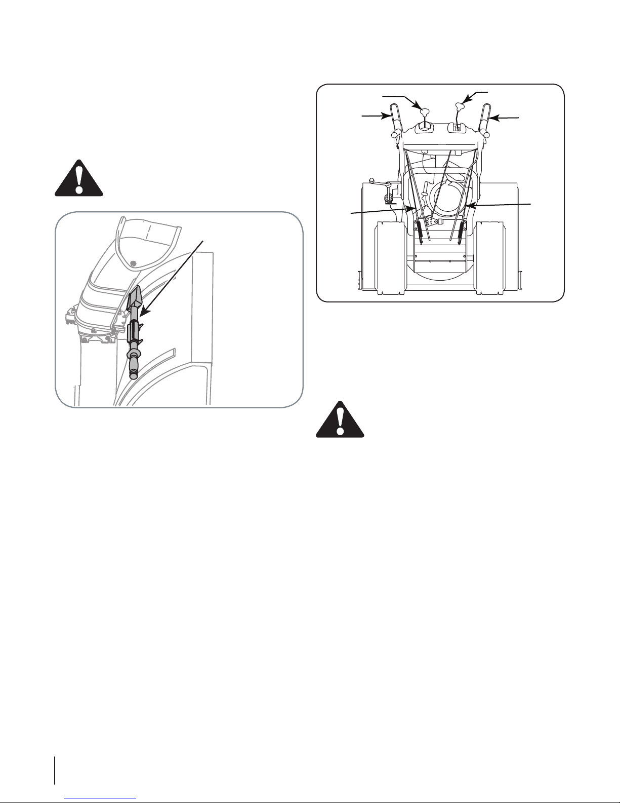
Chute Directional Control
1. Remove the hairpin clip from the lower chute crank as
shown in A of Fig. 3-4.
2. Insert the upper chute crank into the fitting on the lower
chute crank as seen in B of Fig. 3-4.
3. Secure with the hairpin clip previously removed.
Attaching the Chute Assembly
• Remove locknuts and screws securing one of the flange
keepers to the chute assembly. See Figure 3-5.
• Loosen but do not remove the locknuts and screws on the
other two flange keepers.
Fig. 3-5
Fig. 3-6
Fig. 3-4
A
B
8Section 3— ASSembly & Set-Up
Shear Pins Storage (if so equipped)
On some models an area for convenient shear pin storage is
locatetd at the rear of the plastic dash panel. See Fig. 3-7.
Normally the cable ties holding the steering cables against •
the handle are loosely installed on each side of the lower
handle at the factory. Pull the cable ties tight to secure. Cut
the excess from the ends of cable ties.
If not already attached, slip the cables that run from the•
handle panel to the discharge chute into the cable guide.
See Figure 3-8.
Fig. 3-7
Fig. 3-8
Drift Cutters (If Equipped)
Drift cutters should be used when operating the snow thrower in
heavy drift conditions.
On models so equipped, drift cutters and hardware are •
assembled to the auger housing inverted.
Remove the carriage bolts and wingnuts securing the drift•
cutters to the housing.
Reposition drift cutters so they face forward as shown in•
Figure 3-9. Secure with hardware previously removed,
wingnuts should be fastened on the outside of the
housing as shown.
If your unit is not equipped with drift cutters, you may contact
Customer Support as instructed on page 2 for information
regarding price and availability.
Tire Pressure
The tires are over-inflated for shipping purposes. Check the tire
pressure before operating the snow thrower. Refer to the tire side
wall for tire manufacturer’s recommended psi and deflate (or
inflate) the tires as necessary.
WARNING: Under any circumstance do not
exceed manufacturer’s recommended psi. Equal
tire pressure should be maintained at all times.
Excessive pressure when seating beads may cause
tire/rim assembly to burst with force sufficient to
cause serious injury. Refer to sidewall of tire for
recommended pressure.
Fig. 3-9
9Se c t i o N 3 — aS S e M b l y & Se t -up
NOTE: For more details, refer to Drive Control Adjustment in the
Maintenance and Adjustment Section of this manual.
Auger Control Test
Check the adjustment of the auger control as follows:
When the auger control is released and in the disengaged•
“up” position (see Figure 3-11), the cable should have very
little slack, but should NOT be tight.
WARNING: Do not over-tighten the cable. Over-
tightening may prevent the auger from
disengaging and compromise the safety of the
snow thrower.
In a well-ventilated area, start the snow thrower engine as•
instructed in the separate engine manual.
While standing in the operator’s position (behind the snow •
thrower) engage the auger.
Allow the auger to remain engaged for approximately ten •
seconds before releasing the auger control. Repeat this
several times.
With the auger control lever in the disengaged “up” •
position, walk to the front of the machine.
Confirm that the auger has completely stopped rotating•
and shows no signs of motion.
IMPORTANT: If the auger shows any signs of rotating,
immediately return to the operator’s position and shut off the
engine. Wait for all moving parts to stop before readjusting the
auger control cable.
To readjust the control cable, unhook the spring (found•
on the end of the auger cable) from the auger actuator
bracket. See Figure 3-12.
Push the cable coupler through the end of the spring to •
expose the lock nut. See Figure 3-13.
Clean-Out Tool
The clean-out tool is mounted to the rear of the auger housing
and is designed to clear a clogged chute. See Figure 3-10. Refer
to the Operation section for more detailed information regarding
the chute clean-out tool.
NOTE: This item is fastened with a cable tie to the rear of the
auger housing at the factory. Cut the cable tie before operating
the snow thrower.
WARNING: Never use your hands to clean snow
and ice from the chute assembly or auger housing.
Final Adjustments
Make these final adjustments before operating your snow
thrower for the first time. Failure to follow these instructions may
cause damage to the snow thrower.
Wheel Drive Control & Shift Lever
Perform the following test to determine need for adjustment:
Move the shift lever into sixth (6) position. See Figure 4-1.•
With the drive control released (see Figure 3-11), push the•
snow thrower forward, then pull it back. The machine
should move freely.
Engage the drive control and attempt to move the machine•
both forward and back, resistance should be felt.
Move the shift lever into the fast reverse (R2) position and•
repeat the previous two steps.
If you experienced resistance rolling the unit, either when
repositioning the shift lever from 6 to R2 or when attempting
to move the machine with the drive control released, adjust the
drive control immediately. To adjust, proceed as follows:
Loosen the Nylock nut on the drive control cable and •
unthread the cable one full turn. See Figure 3-13.
Recheck adjustment.•
Fig. 3-10
Fig. 3-11
Clean-Out Tool
Drive
Control
Drive
Control
Cable
Auger
Control
Auger
Control
Cable
Shift Lever
Chute Tilt Control
10 Se c t i o N 3— aS S e M b l y & Se t -up

Skid Shoes
The space between the shave plate and the ground can be
adjusted by raising or lowering the skid shoes.
For close snow removal, as when using on a smooth concrete
or asphalt driveway, place the skid shoes in the low position.
Use the middle or high position when the area to be cleared is
uneven. When operating on gravel, always put skid shoes in the
high position. See Figure 3-14.
Adjust skid shoes as follows:
Loosen, but do not remove, the hex flange locknuts which1.
fasten the skid shoe to the auger housing.
Raise or lower the skid shoe to desired position.2.
Retighten the hex nuts loosened earlier.3.
NOTE: Make certain the bottom surface of skid shoe is flat
against the ground to avoid uneven wear.
Repeat on the other side of the snow thrower.4.
CAUTION: Operating a snow thrower equipped
with steel skid shoes may result in damage to
natural stone paved surfaces (e.g. sandstone,
bluestone, limestone). Refer to the Replacement
Parts or Attachments & Accessories sections for
information on available polymer skid shoes.
Thread the Nylock nut outward (down the coupler) to •
provide more slack in the cable and reattach the spring to
the bracket.
Repeat auger control test to verify for proper adjustment.•
Repeat previous steps to adjust more, if necessary.
Fig. 3-12
Fig. 3-13
Fig. 3-14
11Se c t i o N 3 — aS S e M b l y & Se t -up

Now that you have set up your snowthrower for operation, get
acquainted with its controls and features. These are described
below and illustrated on this page. This knowledge will allow you
to use your new equipment to its fullest potential.
NOTE: For detailed starting instructions and more information
on all engine controls, refer to the separate engine manual
packed with your unit.
Speed Selector Lever
The speed selector lever is located on the handle
panel and is used to determine ground speed and
direction of travel.
Forward
There are six forward (F) speeds. Position one (1) is
the slowest and position six (6) is the fastest.
Reverse
There are two reverse (R) speeds. One (R1) is the
slower and two (R2) is the faster.
Augers
When engaged, the augers rotate and draw snow into the auger
housing.
Chute Assembly
Snow drawn into the auger housing is discharged out the chute
assembly.
Skid Shoes
Position the skid shoes based on surface conditions. Adjust
upward for hard-packed snow. Adjust downward when
operating on gravel or crushed rock surfaces.
Headlight (if so equipped)
The headlight is on whenever the engine is running.
Drift Cutters (if so equipped)
The drift cutters are designed for use in deep snow. Their use
is optional for normal snow conditions. Maneuver the snow
thrower so that the cutters penetrate a high standing snow drift
to assist snow falling into the augers for throwing.
Figure 4-1
Drive Control
Shift Lever
Two Way Chute Pitch Control™
Auger Control
Wheel Steering Control
Chute Directional Control
Skid Shoe
Clean-Out Tool
Chute Assembly
Headlight
Augers
Controls and Features 4
12
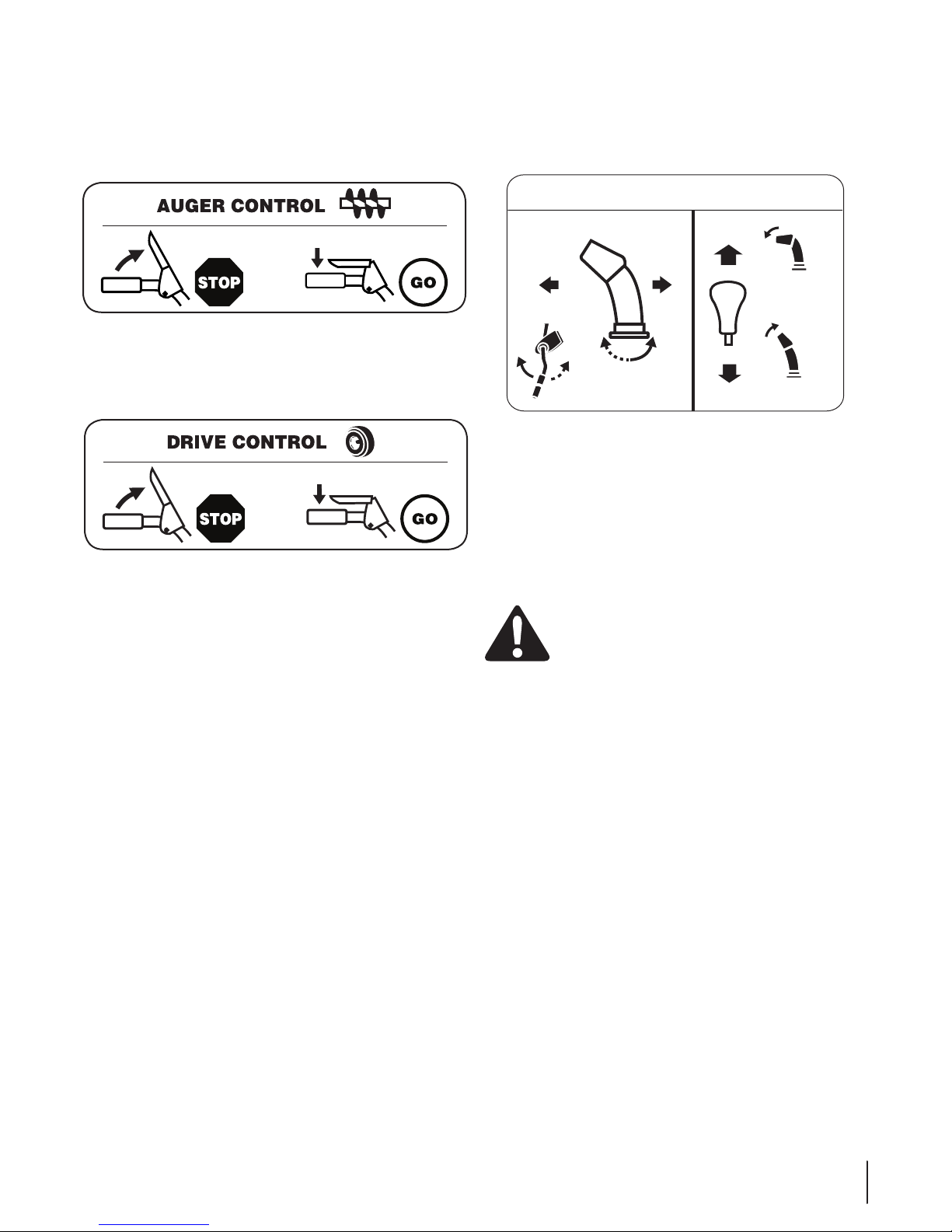
Auger Control
The auger control is located on the left handle. Squeeze the
control grip against the handle to engage the augers and start
snow throwing action. Release to stop.
Drive Control / Auger Clutch Lock
The drive control is located on the right handle. Squeeze the
control grip against the handle to engage the wheel drive.
Release the handle to stop.
The drive control also locks the auger control so that you can
operate the chute directional control without interrupting
the snow throwing process. If the auger control is engaged
simultaneously with the drive control, the operator can release
the auger control (on the left handle) and the augers will remain
engaged. Release both controls to stop the augers and wheel
drive.
NOTE: Always release the drive control before changing speeds.
Failure to do so will result in increased wear on your machine’s
drive system.
Two-Way Chute Control™
This two-way control lever is meant to control the distance of
snow discharge from the chute. Tilt the lever forward or rearward
to adjust the distance snow will be thrown.
Chute Directional Control
The chute directional control can be turned clockwise or
counterclockwise to change the direction in which snow is
thrown.
Wheel Steering Controls
The left and right wheel steering controls are located on the
underside of the handles. Squeeze the right control to turn right;
squeeze the left control to turn left.
NOTE: Operate the snow thrower in open areas until you are
familiar with these controls.
Chute Clean-Out Tool
WARNING! Never use your hands to clear a
clogged chute assembly. Shut off engine and remain
behind handles until all moving parts have stopped
before unclogging.
The chute clean-out tool is conveniently fastened to the rear of
the auger housing with a mounting clip. Should snow and ice
become lodged in the chute assembly during operation, proceed
as follows to safely clean the chute assembly and chute opening:
Release both the Auger Control and the Drive Control.1.
Stop the engine.2.
Remove the clean-out tool from the clip which secures it to3.
the rear of the auger housing.
Use the shovel-shaped end of the clean-out tool to4.
dislodge and scoop any snow and ice which has formed in
and near the chute assembly.
Refasten the clean-out tool to the mounting clip on the5.
rear of the auger housing, start the snow thrower’s engine.
While standing in the operator’s position (behind the snow 6.
thrower), engage the auger control for a few seconds to
clear any remaining snow and ice from the chute assembly.
CHUTE DIRECTIONAL CONTROL
DISCHARGE
LEFT
DISCHARGE
RIGHT
CHUTE TILT
DOWN
CHUTE TILT
UP
13Se c t i o N 4 — co N t r o l S a N d fe a t u r e S

Starting and Stopping the Engine
Refer to the Engine Operator’s Manual packed with your snow
thrower for instructions on starting and stopping the engine.
To Engage Drive
With the throttle control in the Fast (rabbit) position, move1.
shift lever into one of the six forward (F) positions or two
reverse (R) positions. Select a speed appropriate for the
snow conditions and a pace you’re comfortable with.
NOTE: When selecting a Drive Speed, use the slower speeds
until you are comfortable and familiar with the operation of the
snowthrower.
NOTE: NEVER reposition the shift lever (change speeds or
direction of travel) without first releasing the drive control and
bringing the snowthrower to a complete stop. Doing so will
result in premature wear to the snowthrower’s drive system.
Squeeze the drive control against the handle the snow2.
thrower will move. Release it and drive motion will stop.
To Engage Augers
To engage augers and start snow throwing, squeeze the1.
left hand auger control against the left handle. Release to
stop augers.
While the auger control is engaged, squeeze the drive2.
control to move, release to stop. Do not shift speeds while
the drive is engaged.
NOTE: This drive lever also locks auger control so you can turn
the chute control without interrupting the snow throwing
process.
Release the auger control; the interlock mechanism should3.
keep the auger control engaged until the drive control is
released.
Release the drive control to stop both the augers and4.
the wheel drive. To stop the auger, both levers must be
released.
Operating Tips
NOTE: Allow the engine to warm up for a few minutes. The
engine will not develop full power until it reaches operating
temperature.
WARNING: The temperature of the muffler and the
surrounding areas may exceed 150° F (65° C). Avoid
these areas.
If possible, remove snow immediately after it falls.1.
Discharge snow downwind whenever possible.2.
Slightly overlap each previous path.3.
Set the skid shoes 1/4” below the shave plate for normal4.
usage. Adjust them upward for hard-packed snow and
downward when using on gravel or crushed rock.
Replacing Shear Pins
The augers are secured to the spiral shaft with two shear pins
and cotter pins. If the auger should strike a foreign object or ice
jam, the snow thrower is designed so that the pins may shear. If
the augers will not turn, check to see if the pins have sheared.
See Fig. 5-1.
cAutIoN: NEVER replace the auger shear pins with
anything other than OEM Part No. 738-04155.
replacement shear pins. Any damage to the auger
gearbox or other components as a result of failing to
do so will NOT be covered by your snow thrower’s
warranty.
WARNING! Always turn off the snow thrower’s
engine and remove the key prior to replacing shear
pins.
Fig. 5-1
Operation 5
14

Lubrication
Drive and Shifting Mechanism
At least once a season or after every 25 hours of operation,
lubricate any chains, sprockets, gears, bearings, shafts, and the
shifting mechanism at least once a season. Use engine oil or a
spray lubricant. Refer to Figure 6-2.
Allow the engine to run until it is out of fuel.1.
Carefully pivot the snow thrower up and forward so that it2.
rests on the auger housing.
Remove the frame cover from the underside of the snow3.
thrower by removing the self-tapping screws which secure
it.
Apply a light coating of engine oil (or 3-in-1 oil) to the hex4.
shaft.
NOTE: When lubricating the hex shaft, be careful not to get any
oil on the aluminum drive plate or the rubber friction wheel.
Doing so will hinder the snow thrower’s drive system. Wipe off
any excess or spilled oil.
Gear Case
The auger gear case is equipped with a grease fitting. Lubricate
with grease once a season (order part number 737-0168). See
Figure 6-3.
NOTE: To relieve pressure, remove the vent plug before
lubricating the gear case. See Figure 6-3. Failure to do so could
result in damage to the gear case seals.
Maintenance
WARNING! Before servicing, repairing, lubricating,
or inspecting, disengage all controls and stop
engine. Wait until all moving parts have come to a
complete stop. Remove the ignition key, disconnect
the spark plug wire and ground it against the engine
to prevent unintended starting. Always wear safety
glasses during operation or while performing any
adjustments or repairs.
Engine
Refer to the separate engine manual packed with your unit for all
engine maintenance and lubrication instructions.
Shave Plate and Skid Shoes
The shave plate and skid shoes on the bottom of the snow
thrower are subject to wear. They should be checked periodically
and replaced when necessary.
NOTE: Some units are equipped with reversible skid shoes and
may be turned over to increase their lifespan.
To remove skid shoes:
Remove the carriage bolts (and washers if equipped)1.
and hex flange nuts which secure the skid shoes to the
snowthrower.
Reassemble new skid shoes with previously removed2.
hardware. Refer to Figure 6-1.
To remove shave plate:
Remove the carriage bolts and hex nuts which attach it and1.
the skid shoes to the snowthrower housing.
Reassemble new shave plate, making sure heads of carriage2.
bolts are to the inside of housing. Tighten securely.
Figure 6-1
Figure 6-2
Hex Shaft
Maintenance & Adjustments 6
15

Chute Bracket Adjustment
If the spiral at the bottom of the chute directional control is not
fully engaging with the chute assembly, the chute bracket can be
adjusted. To do so:
Loosen the two nuts which secure the chute bracket and1.
reposition it slightly. See Figure 6-5.
Retighten the nuts.2.
Figure 6-5
Wheels
At least once a season, remove wheels. Clean and coat the axles
with a multipurpose automotive grease before reinstalling
wheels.
Auger Shaft
At least once a season, remove the shear pins on auger shaft.
Spray lubricant inside shaft, around the spacers. Also lubricate
the flange bearings found at either end of the shaft. See Figure
6-3.
Augers
The augers are secured to the spiral shaft with shear pins•
and cotter pins. If the auger should strike a foreign object
or ice jam, the snowthrower is designed so that the pins
may shear. See Figure 6-3.
If the augers will not turn, check to see if the pins have•
sheared. Replacement shear pins have been provided
with the snowthrower. When replacing pins, spray an oil
lubricant into shaft before inserting new pins.
Adjustments
Shift Cable
If the full range of speeds (forward and reverse) cannot be
achieved, refer to the Figure 6-4 and adjust the shift cable as
follows:
Place the shift lever in the fastest forward speed position.1.
Loosen the hex nut on the shift cable index bracket. See2.
Fig. 6-4.
Pivot the bracket downward to take up slack in the cable.3.
Retighten the hex nut.4.
If further adjustment is necessary move the cable to one of5.
the alternate holes.
Figure 6-4
Grease Fitting
SpacersBow-Tie Pins
Vent Plug
Shear Pins
Figure 6-3
16 Se c t i o n 6— Ma i n t e n a n c e & ad j u S t M e n t S
Drive Control
WARNING: Run the engine completely dry of
gasoline before tipping snowthrower.
Refer to the Final Adjustment section of the Set-Up instructions
to adjust the drive control. To further check the adjustment,
proceed as follows:
1. Tip the snow thrower forward, allowing it to rest on the
auger housing.
2. Remove the frame cover underneath the snow thrower by
removing the self-tapping screws. See Figure 6-6.
3. With the wheel drive control released, check if there is
clearance between friction wheel and drive plate in all
positions of the shift lever. See Figure 6-7.
4. With the drive control lever engaged, check if the friction
wheel solidly contacts the drive plate. See Figure 6-7. If not,
adjust as follows:
a. Thread the lock nut outward (down the coupler)
to lengthen the cable and allow the unit to move
freely when the control is released. Refer to Fig.
3-13. Thread the lock nut inward (up the coupler) to
shorten the cable to reduce slippage and prevent
the machine from being easily moved with the drive
control engaged.
5. Reassemble the frame cover.
NOTE: Refer to the “Wheel Drive Control & Shift Lever” in the Set-
Up instructions to test drive control adjustment.
Auger Control
Refer to the Assembly & Set-up section, “Auger Control Test” for
instructions on adjusting the auger control cable.
Chute Assembly
The remote chute control cables have been pre-adjusted at the
factory. Move the remote chute lever on the control panel back
and forward to adjust angle of the chute assembly.
Skid Shoes
Refer to the Assembly and Set-up section for instructions on
adjusting the skid shoes.
Tire Pressure
Refer to “Assembly & Set-Up” section of this manual.
Off-Season Storage
If the snow thrower will not be used for 30 days or longer, follow
the storage instructions below.
1. Lubricate the machine as instructed earlier in this section.
2. Store in a clean, dry area.
3. If storing the snow thrower in an unventilated area,
rustproof the machine using a light oil or silicone to coat
the snow thrower.
4. Clean the exterior of the engine and the snow thrower.
IMPORTANT: When storing unit or when it is not being serviced,
it is to remain in the operating position with both wheel and
auger housing on the ground.
NOTE: Refer to the Engine Operator’s Manual for information on
storing your engine.
Figure 6-7
Figure 6-6
Axle
Support
Bracket
Opening
Drive
Plate
Friction
Wheel
17Section 6 — Maintenance & adjuStMentS
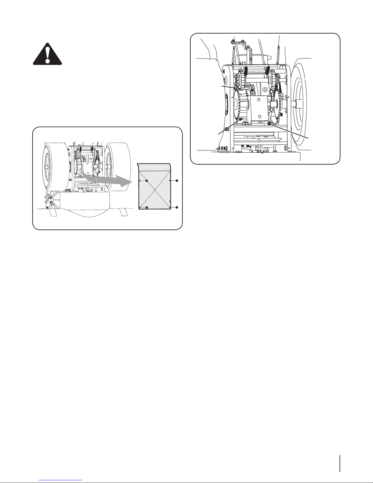
Belt Replacement
To remove and replace either the auger belt or the drive belt,
follow the steps below and then proceed to the specific steps
listed under respective sub-headings.
Disconnect the chute crank assembly by removing the two1.
nuts which secure the chute bracket to the chute adapter.
See Figure 7-1.
Remove the plastic belt cover, located near the engine, by2.
removing the three self-tapping screws that secure it. See
Figure 7-2.
Loosen the bolt shown in Figure 7-3 securing3.
the belt keeper bracket and remove the other
bolt. Push the belt keeper and bracket up off the
engine pulley.
Auger Belt Replacement
Remove the clip and flat washer from the ferrule in order1.
to disconnect the auger idler rod from the brake bracket
assembly. See Figure 7-4.
Slip the auger belt (the front belt) off the engine pulley.2.
Figure 7-4
Figure 7-1
Figure 7-2
Figure 7-3
Nuts &
Washers
Loosen
Remove
Ferrule
Auger Idler Rod
Hairpin
Clip and
Washer
Service 7
18
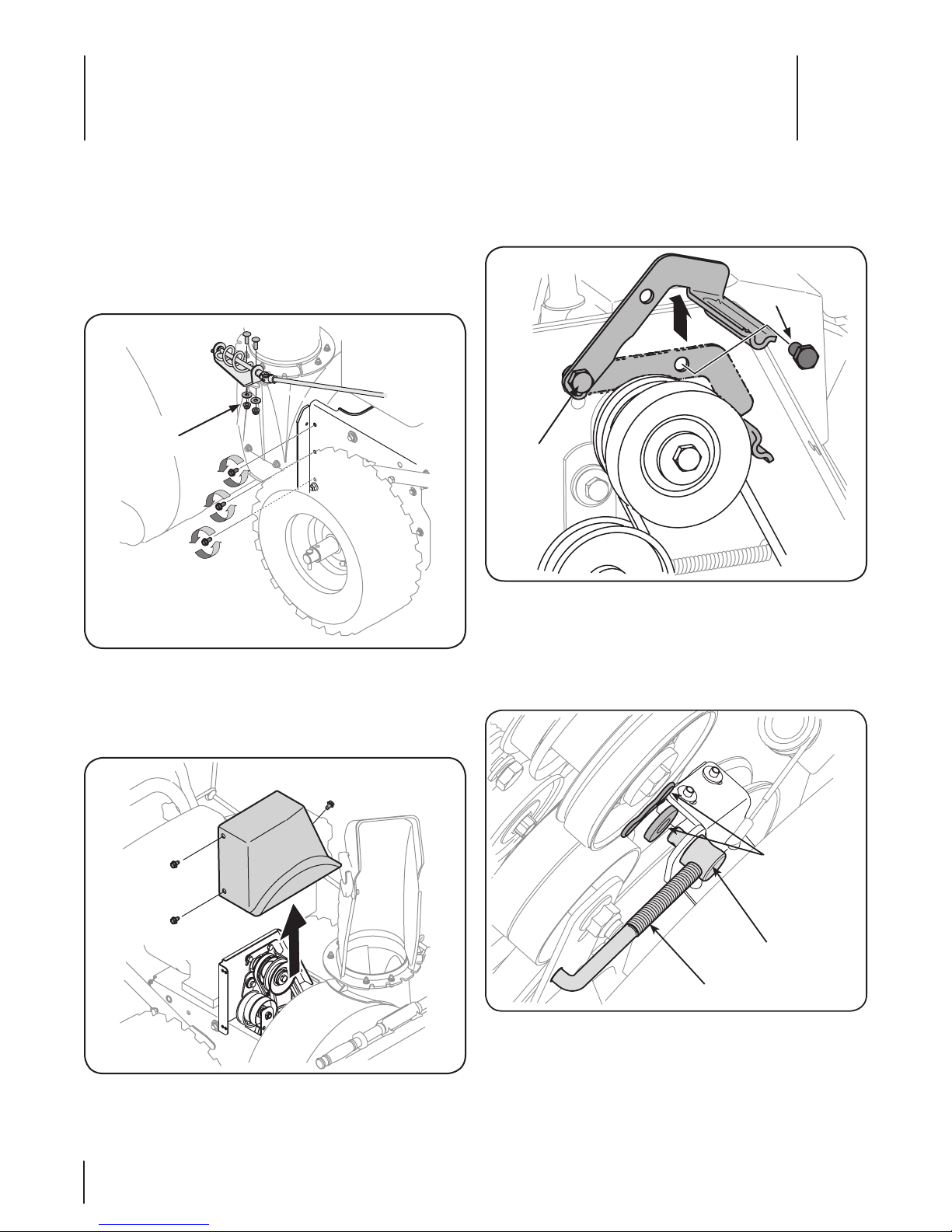
Pull the brake bracket assembly towards the cable guide3.
roller and unhook the auger cable “Z” fitting. See Figure
7-5.
From both sides of the the frame assembly, use a 1/2”4.
wrench to remove the three hex tap screws securing the
frame to the auger housing assembly. See Figure 6-8.
NOTE: Do not remove the lower hex flange lock nut on
each side.
Place a block of wood underneath the auger housing as5.
shown in Figure 7-6 and separate auger housing from the
frame by tilting the housing forward and pulling up the
handles.
a. Block the impeller with a piece of wood to prevent6.
if from spinning and use a 1/2” wrench to remove
the hex screw and washer from the center of the
pulley on the auger housing. See Figure 7-7.
b. Lift the brake bracket assembly out of the pulley
groove and slide the pulley assembly off the posts
of the auger pulley adapter to remove the old belt.
Refer to Figure 7-8.
NOTE: The pulley adapter may slide off the auger input
shaft when removing the pulley. Use extra caution to
ensure the adapter does fall and/or get damaged when
removing the pulley.
Figure 7-7
Figure 7-5
Z-fitting
Figure 7-6
Screws
Figure 7-8
A
C
B
Adapter Post
Belt Keeper
Pulley Slot
19Se c t i o n 7 — Se r v i c e

c. Place the new auger belt in the V-groove of the
auger pulley and place the pulley w/belt inside
the belt keepers.
Turn the pulley as necessary to align its three slots7.
approximately with the posts of the pulley adapter, then
move the brake bracket assembly away from the input
shaft. While aligning the pulley slots and adapter posts,
push the auger pulley fully onto the adapter. Refer to
Figure 7-8.
NOTE: If the pulley adapter was removed with the pulley, align
the splines of the pulley adapter and auger input shaft, and push
the pulley and adapter onto the input shaft. Refer to Fig. 7-8.
Slide the washer onto the hex screw removed earlier and8.
apply Loctite 262 to the threads of the hex screw.
Insert the hex screw through the pulley assembly and into9.
the threads of the input shaft. Torque the hex screw to
250-325 in. /lbs. to secure the auger pulley assembly on
the input shaft.
If also replacing the drive belt, proceed to the “Drive Belt”
instruction. If not, reassemble by performing the previous steps
in the opposite order and manner of removal.
NOTE: Make sure to remove the piece of wood blocking the
impeller.
Proper Adjustment: With the auger clutch lever in the
disengaged position, the top surface of the new belt should be
even with the outside diameter of the pulley.
To adjust, disconnect ferrule from brake bracket assembly10.
and thread ferrule in (towards idler) to increase tension on
belt, and out to decrease tension. See Figure 7-4.
NOTE: The brake puck must always be firmly seated in the pulley
groove when auger control is disengaged.
IMPORTANT: Repeat the “Auger Drive Control Test” from the
Assembly section before operating snowthrower.
Drive Belt
If not already done, remove auger belt as previous1.
instructed.
a. Pull the idler pulley away from the backside of the
drive belt to relieve the tension.
b. Slide the drive belt off the idler pulley. See Figure 7-9.
Carefully release the idler pulley.
Remove the belt from the bottom drive pulley.2.
Remove the belt from the engine pulley.3.
Install the new belt on the pulleys in the reverse order and4.
re-tension with the idler pulley.
Reassemble your unit by performing the previous steps in5.
the opposite order.
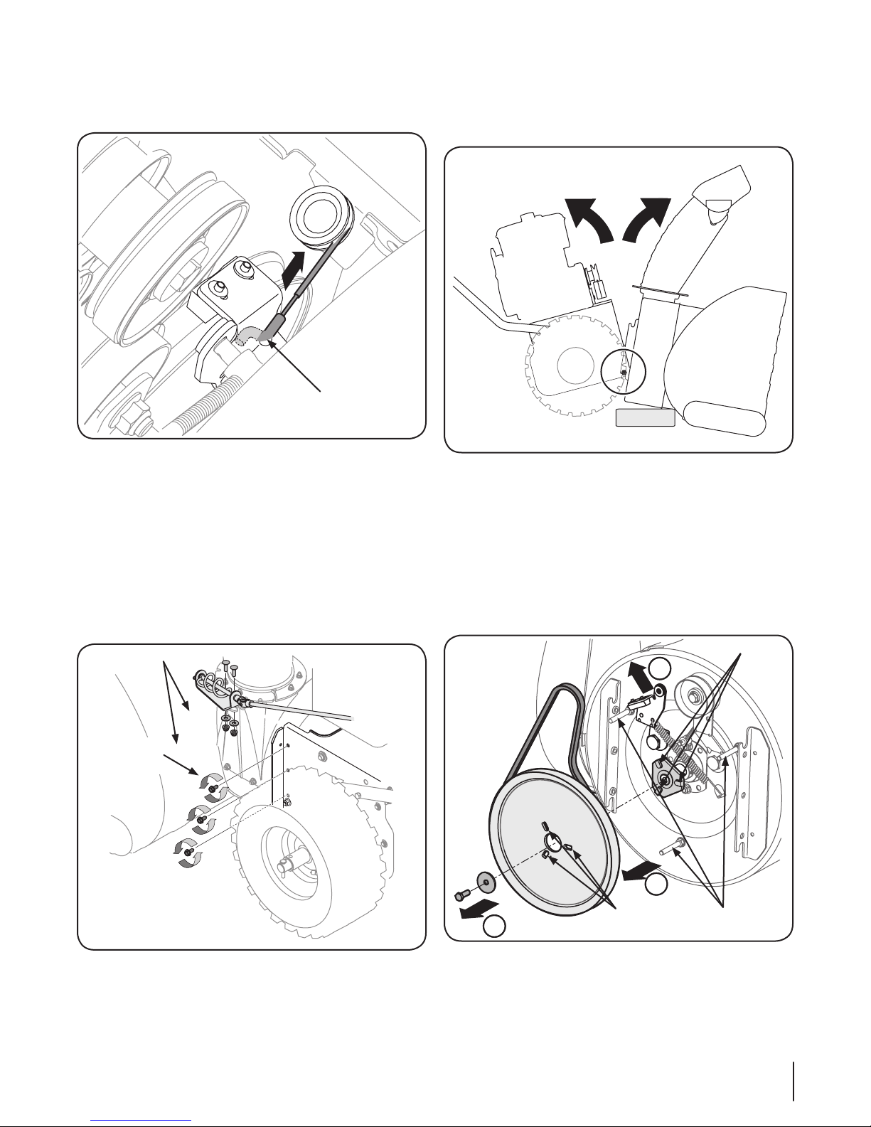
Changing Friction Wheel
WARNING: Run the engine completely dry of
gasoline before tipping snowthrower.
Tip the snowthrower up and forward, so that it rests on the•
housing.
Remove screws from the frame cover underneath the•
snowthrower. See Figure 6-6.
Remove the right wheel(s) from the axle. See Figure 7-10.•
Using a 3/4” wrench, hold the hex shaft and remove the•
hex bolts and cupped washer and bearing from left side of
the frame. Refer to Figure 7-10.
Figure 7-9
2
3
1a
1b
Figure 7-10
20 Se c t i o n 7— Se r v i c e
Table of contents
Other Troy-Bild Snow Blower manuals


