Trumpf TruConvert AC 3025 User manual

Operator's manual
TruConvert AC 3025,
TruConvert System Control


Operator's manual
TruConvert AC 3025,
TruConvert System Control
Original operator's manual
Edition 2020-06-10

Order Information Please specify when ordering this document:
Operator's manual
TruConvert AC 3025, TruConvert System Control
Edition 2020-06-10
Document number A67-0141-00.BKEN-001-05
Address for orders TRUMPF Hüttinger GmbH + Co. KG
Technische Redaktion
Bötzinger Straße 80
D-79111 Freiburg
Fon: +49 761 8971 - 0
Fax: +49 761 8971 - 1150
Internet: http://www.trumpf-huettinger.com
E-Mail: [email protected]
For "partly completed machinery" in accordance with the EC
Machinery Directive, this document corresponds to the
assembly instructions.
© TRUMPF Hüttinger GmbH + Co. KG

Good to know
Provide the serial number when you contact the Service depart-
ment. The serial number can be found on the name plate of the
device.
How to reach our Service department:
+49 761 8971-2170
+49 761 8971-1178
A67-0141-00.BKEN-
001-05
2020-06-10 Good to know I
Need help?
Telephone
Fax
E-mail

II Good to know 2020-06-10 A67-0141-00.BKEN-
001-05

Table of contents
1 Safety 4
1.1 Storing the operating instructions 4
1.2 Warning signs 4
1.3 Using the device 4
1.4 Authorized personnel 5
1.5 Warning signs on the AC-DC module 6
1.6 What you must know as an operator 6
1.7 Dangers from high voltages 7
Protective measures taken by the manu-
facturer
8
1.8 What you must know as an operator 8
2 Description 9
2.1 Fields of application 9
2.2 Function description 9
2.3 Configurations 9
2.4 Construction 12
Overview 13
Rear side 13
Display elements 14
3 Technical specifications 15
3.1 Data TruConvert AC 3025 15
3.2 TruConvert System Control data 20
4 Interfaces 22
4.1 Mains power connection 22
4.2 Potential equalization 23
4.3 DC link 23
4.4 Contactor release contact and mains voltage
measurement
24
4.5 24 V supply voltage (DC) 25
4.6 Communication interfaces 25
4.7 Interfaces on the system control 26
24 V supply voltage (DC) 26
Ethernet 27
RS-485 27
A67-0141-00.BKEN-
001-05
2020-06-10 Table of contents 1

5 Standards and directives 29
5.1 CE certification 29
5.2 EU declaration of conformity TruCon-
vert AC 3025
30
6 Installation 31
6.1 Inspecting the delivery 31
6.2 Disposing of packaging material 31
6.3 Transport 31
6.4 Storage conditions 31
6.5 Requirements for the site 31
6.6 Electrical connection 32
Establishing electrical connection 33
Connection diagram 36
6.7 Setting grid codes 37
6.8 Dismantling 39
6.9 Shipping the module 40
6.10 Disposing of the module 40
7 Operation 41
7.1 Commissioning 41
Performing initial commissioning 41
7.2 Operation via web-based user interface 45
Calling up the web-based user interface 45
Menu structure 47
7.3 Operation via Modbus 47
Establishing a connection 48
Addressing modules directly in Modbus
register
48
Modbus Register Map 49
7.4 Transmission of power 55
Switching the transmission of power on/off 55
7.5 Displaying and resetting messages 56
User interface: displaying and resetting
messages
56
Modbus: displaying and resetting mes-
sages
58
7.6 Overload 59
Operating with overload 59
Examples: Reduce and then again
increase overload capacity
60
2Table of contents 2020-06-10 A67-0141-00.BKEN-
001-05

7.7 Actual values 61
Display actual values 61
7.8 Process set values 61
Set process set values 61
7.9 Data backup 62
Saving data 62
7.10 System configuration 62
Setting the system configuration 63
7.11 System control 65
Setting the system time 65
Changing network settings 65
7.12 Software update 66
Perform software update 66
7.13 Device information 67
Displaying device information 67
7.14 State diagram 68
8 Maintenance 69
8.1 Periodic check of the environmental condi-
tions
69
8.2 Cleaning 69
8.3 Exchanging fans 69
8.4 Performing software updates 69
9 Troubleshooting 70
9.1 Fault indication and messages 70
Fault indication with the LEDs 70
9.2 Messages 70
A67-0141-00.BKEN-
001-05
2020-06-10 Table of contents 3

1. Safety
1.1 Storing the operating instructions
These operating instructions contain safety notices that must be
observed during installation and maintenance. Therefore, keep
the operating instructions in a safe place for the entire life cycle
of the device.
Include the operating instructions if you sell the device or set it
up at another location.
1.2 Warning signs
Certain activities can cause danger during operation. Corre-
sponding warning signs concerning the dangers should precede
instructions concerning the activities. Danger signs are located
on the device.
A warning sign contains signal words which are explained in the
following table:
Signal word Description
DANGER Indicates a major danger. If it is not avoided,
serious injuries or death will result.
WARNING Indicates a dangerous situation. If it is not
avoided, it may lead to serious injuries.
CAUTION Indicates a potentially dangerous situation. If it
is not avoided, injuries may occur.
NOTICE If such a situation is ignored, material damage
may result.
Description of the signal words Tab. 1
1.3 Using the device
The device is a bidirectional inverter. It is used for charging a
DC link from a three-phase grid and for feeding the grid from
the DC link's energy.
■The power and the energy flow direction are adjustable.
■The device draws sinusoidal current from the mains or deliv-
ers sinusoidal current to the mains. The power factor cosφ
is adjustable.
■The DC link voltage is balanced to earth.
4Safety 2020-06-10 A67-0141-00.BKEN-
001-05
Typical fields of application

Any use not listed under "Typical fields of application" contra-
venes the intended purpose. TRUMPF is not liable for any ensu-
ing damages, in particular for property damage, personal injury
and loss of production. The operator bears all risks. The war-
ranty is rendered null and void.
Impermissible uses include, for example:
■Use of incorrect components.
■Operation on mains voltage outside the specification.
■Faulty installation (e.g., cables reversed).
■Use in unauthorized installation position.
■Misuse by untrained personnel.
■Use in unsuitable environmental conditions:
− Condensation, icing.
− Conductive soiling.
− Corrosive conditions (e.g. battery fumes, salt spray).
− Voltages outside of overvoltage category III (max. 4 kV
impulse withstand voltage).
− Operation at more than 2000 m above sea level.
− Outdoors.
− Failure to observe pollution degree 2 environmental con-
dition.
− In an explosive environment.
1.4 Authorized personnel
Installation, operation, configuration and maintenance work may
only be performed by authorized, trained and instructed person-
nel.
Authorized persons must be trained and be familiar with the
standards and regulations relevant to their tasks.
It is the duty and responsibility of the operator to maintain the
qualifications of the authorized personnel. The authorized per-
sonnel must therefore be trained at regular intervals.
The following activities may only be performed by authorized per-
sons:
■Setting up the AC-DC module.
■Connecting the AC-DC module.
■Commissioning the AC-DC module.
■Dismantling the AC-DC module.
■Operating the AC-DC module.
A67-0141-00.BKEN-
001-05
2020-06-10 Safety 5
Liability exclusion
Impermissible uses

1.5 Warning signs on the AC-DC module
1 Read operating instructions
2 Dangerous voltage
3 Dangerous residual voltage
4 Danger due to the weight of
the device
5 Danger due to contact current
Warning signs on the AC-DC module Fig. 1
1.6 What you must know as an operator
Note
All warning signs must be present and legible.
If one or more of these warning signs is missing or not legible,
contact TRUMPF to request new warning signs.
Warning sign Meaning
This sign indicates that the operat-
ing instructions must be read.
Sign warns of hazardous voltage.
6Safety 2020-06-10 A67-0141-00.BKEN-
001-05

Warning sign Meaning
Sign warns of hazardous residual
voltage.
This sign warns of dangers that
arise from the weight of the device.
Sign warns of contact current.
Meaning of the warning signs Tab. 2
1.7 Dangers from high voltages
Life threatening voltage!
The voltages present at the AC-DC module are life-
threatening.
ØOnly have work on the AC-DC module performed by author-
ized, trained and instructed personnel.
The AC-DC module produces voltages that can endanger
human life and health. These voltages occur both in the AC-DC
module as well as at the outputs of the AC-DC module.
The AC-DC module's connection cables carry voltages that are
life-threatening.
A person who comes into contact with live AC-DC module parts
may be killed or severely injured.
Simultaneous control via web-based user interface and
Modbus is possible!
Power transmission stopped using the user interface can
be started again and reversed via Modbus.
ØBefore carrying out work on the device, deenergize all sup-
ply lines and secure against reenergizing.
ØMake sure that the device is controlled via one channel
only (user interface or Modbus).
A67-0141-00.BKEN-
001-05
2020-06-10 Safety 7
WARNING
WARNING

Protective measures taken by the
manufacturer
The AC-DC module is installed in an enclosed metal casing.
1.8 What you must know as an operator
1. The AC-DC module must not be opened.
There are no parts within the device that can be serviced by
the user.
2. Only operate the AC-DC module within the conditions descri-
bed in chapter "Technical specifications".
3. Only operating personnel without pacemaker or implants
may work in the operational site.
4. For the electrical connection, use only cables that are in per-
fect condition and have the correct dimensions.
5. Periodically retest acc. to DGUV regulation 3 (DGUV = Deut-
sche Gesetzliche Unfallversicherung – German Statutory
Accident Insurance Association).
8Safety 2020-06-10 A67-0141-00.BKEN-
001-05

2. Description
2.1 Fields of application
The fields of application are described in chapter Safety, (see
"Typical fields of application", pg. 4).
The TruConvert System Control external control must be used
to monitor and control the AC-DC module.
2.2 Function description
■The AC-DC module draws energy from a three-phase grid
and feeds it into a DC link.
■The AC-DC module draws energy from a DC link and feeds
it into a three-phase grid.
1 Three-phase grid
2 TruConvert AC 3025
3 DC link
Description of principle Fig. 2
The AC-DC module can be operated:
■with a PC with a web browser
■via Modbus
In both cases, the TruConvert System Control control device
must be connected upstream (see "Fig. 3", pg. 10).
2.3 Configurations
■The TruConvert AC 3025 must always be operated together
with a TruConvert System Control.
■TruConvert AC 3025 can be operated on its own on a DC
link ("DC link").
A67-0141-00.BKEN-
001-05
2020-06-10 Description 9
Control
Operation modes
Description of principle
Operation
Permissible configurations
■Multiple TruConvert AC 3025 units can be operated simulta-
neously on the DC link.
■One TruConvert AC 3025 can be operated together with up
to 16 TruConvert DC 1008.
■The connection of other DC voltage converters is only per-
missible in consultation with TRUMPF.
■The parallel connection of TruConvert AC 3025 with other
bidirectional inverters on the DC link side is permissible only
in consultation with TRUMPF.
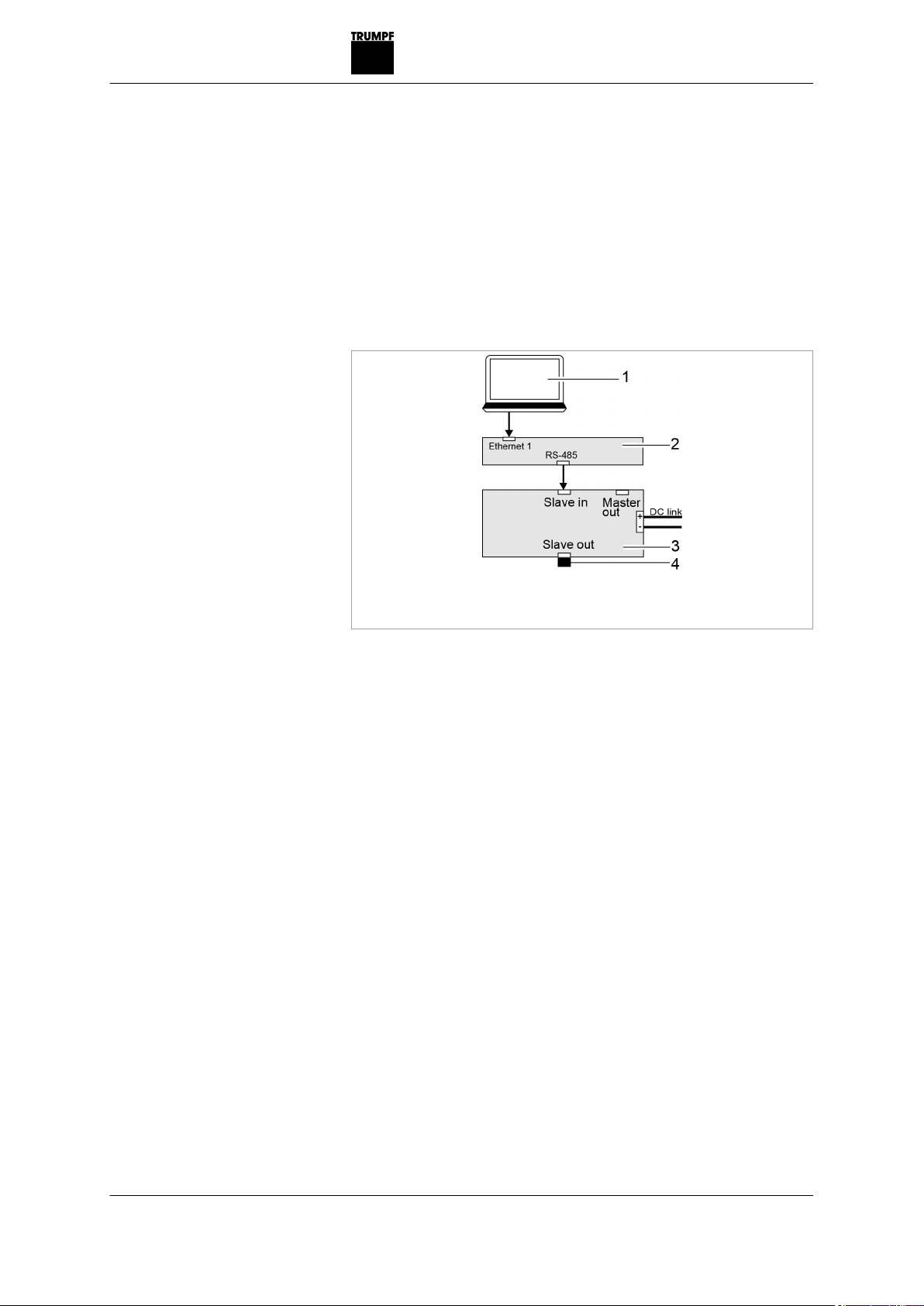
1 PC
2 TruConvert System Control
3 TruConvert AC 3025
4 Terminating resistor
1 x TruConvert System Control, 1 x TruConvert AC 3025 Fig. 3
10 Description 2020-06-10 A67-0141-00.BKEN-
001-05
Impermissible configurations
One TruConvert System
Control controls one
TruConvert AC 3025

1 PC with web browser or Mod-
bus master
2 TruConvert System Control
3 DC link
4 Terminating resistor
1 x TruConvert System Control, n x TruConvert AC 3025 Fig. 4
A67-0141-00.BKEN-
001-05
2020-06-10 Description 11
One TruConvert System
Control controls several
TruConvert AC 3025
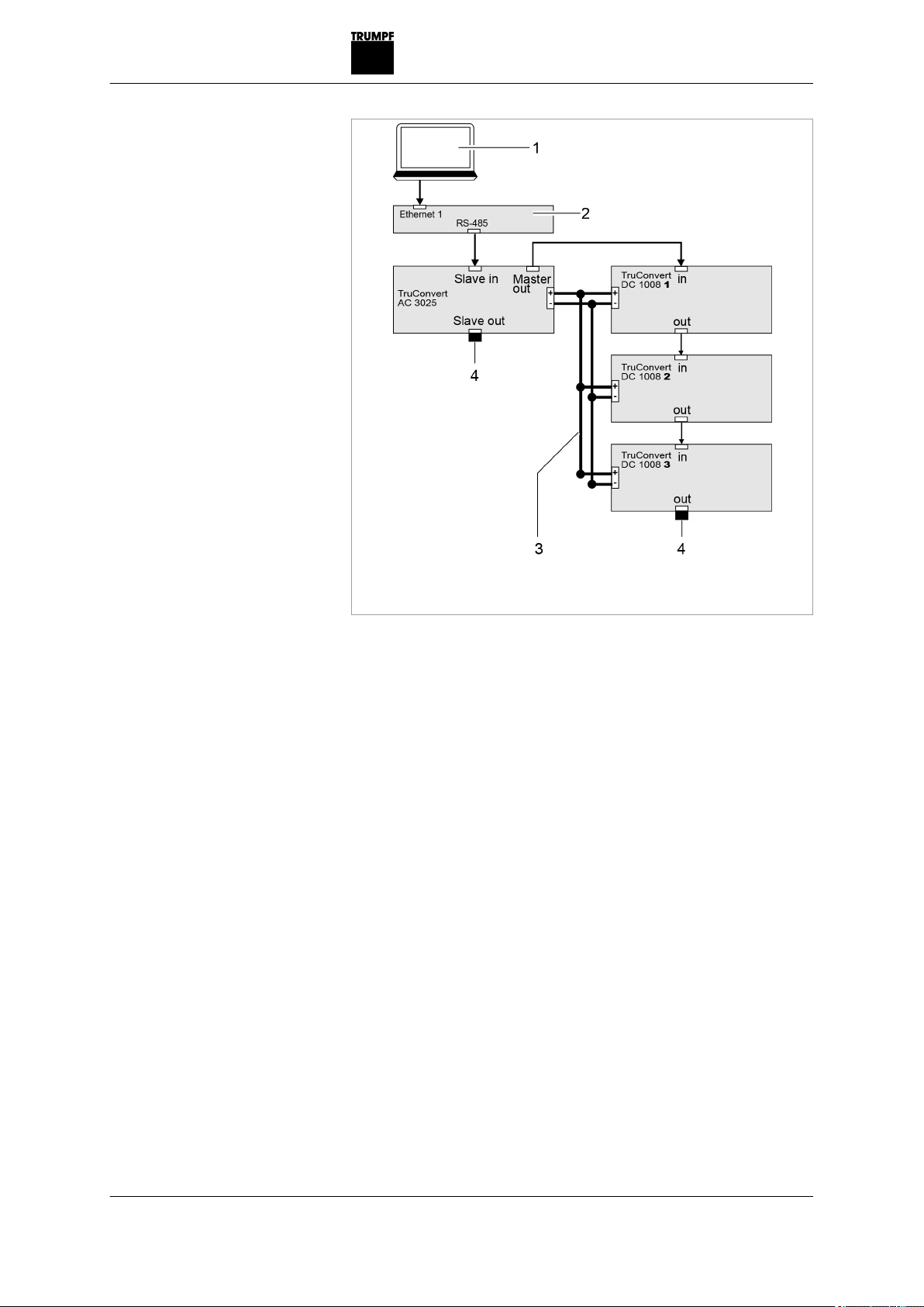
1 PC
2 TruConvert System Control
3 DC-Zwischenkreis
4 Terminating resistor
One TruConvert System Control controls one TruCon-
vert AC 3025 and m x TruConvert DC 1008
Fig. 5
2.4 Construction
The AC-DC module is housed in an enclosed 19-inch metal
housing.
12 Description 2020-06-10 A67-0141-00.BKEN-
001-05
One TruConvert System
Control controls one
TruConvert AC 3025 and
several TruConvert DC 1008

Overview
1 Device name
2 Name plate
3 Status LEDs 3 Fan (air is sucked)
Overall view of the TruConvert AC 3025 Fig. 6
Rear side
1 Mains input ("Mains")
2 Contactor release contact and
mains voltage measurement
("Contactor / Mains Measure-
ment")
3 24 V supply voltage
4 DC link voltage ("DC Link")
5 LED status display
6 Data cable "MASTER OUT"
7 Threaded bolts for potential
equalization
8 Data cable "SLAVE IN"
9 Data cable "SLAVE OUT"
TruConvert AC 3025 rear side Fig. 7
A67-0141-00.BKEN-
001-05
2020-06-10 Description 13

Display elements
Status LEDs on TruConvert AC 3025 and TruConvert Sys-
tem Control
Fig. 8
Device condition
LED Bootloader Initialize Errors Idling Operation
1 (green) on Flashing off Flashing Flashing
2 (yellow) Flashing Flashing off off LED indicates the energy direction.
■ Illuminates if the energy flows from
mains to the DC link.
■ Flashes if the energy flows from the
DC link to mains.
3 (red) on Flashing Flashing off off
Status LEDs Tab. 3
14 Description 2020-06-10 A67-0141-00.BKEN-
001-05
Other manuals for TruConvert AC 3025
1
This manual suits for next models
1
Table of contents
Popular Inverter manuals by other brands


B PLUS TV
B PLUS TV ELZapp user guide

Deye
Deye SUN-30K-G04 user manual

Black & Decker
Black & Decker 200 WATT instruction manual

Selectronic Australia
Selectronic Australia LD250-24 owner's manual

SunSynk
SunSynk SYNK-7K-SG05LP1 user manual

HiQ Solar
HiQ Solar TrueString TSXL380-8k-VN Installation & operator's manual


