HiQ Solar TrueString TSXL380-8k-VN Administrator Guide
TrueString TSXL380-8k-VN
Grid-Interactive Inverter
Installation & Operators Manual

770-00015
About HiQ Solar
HiQ Solar is a leader in advanced energy conversion technology. HiQ products include compact high
efficiency commercial power converters for utility interconnection of solar and battery energy systems.
Contact Information
Address: Corporate Headquarters
1259 Reamwood Ave.
Sunnyvale, CA 94089 USA
Website: http://www.hiqsolar.com
Disclaimer
UNLESS SPECIFICALLY AGREED TO IN WRITING, HIQ SOLAR:
(a) MAKES NO WARRANTY AS TO THE ACCURACY, SUFFICIENCY OR SUITABILITY OF ANY
TECHNICAL OR OTHER INFORMATION PROVIDED IN ITS MANUALS OR OTHER
DOCUMENTATION.
(b) ASSUMES NO RESPONSIBILITY OR LIABILITY FOR LOSS OR DAMAGE, WHETHER DIRECT,
INDIRECT, CONSEQUENTIAL OR INCIDENTAL, WHICH MIGHT ARISE OUT OF THE USE OF SUCH
INFORMATION. THE USE OF ANY SUCH INFORMATION WILL BE ENTIRELY AT THE USER’S RISK.
HiQ Solar cannot be responsible for system failure, damages, or injury resulting from improper
installation or handling of their products.
Notice of Copyright
TrueString TSXL380-8k-VN Grid-Interactive Inverter Owner’s Manual © 2020 by HiQ Solar. All
Rights Reserved.
Trademarks
TrueString, the TrueString logo, HiQ Solar, and the phrase “TrueString by HiQ Solar” are trademarks
owned and used by HiQ Solar, Inc. These trademarks may be registered in the United States and
other countries.
Date and Revision
January 2020, Revision A
Part Number
770-00015

770-00015
Table of Contents
Important Safety Instructions.............................................................................................................. 5
Symbols Used................................................................................................................................................ 5
Product Labels ............................................................................................................................................... 5
General Safety ............................................................................................................................................... 5
Introduction...................................................................................................................................................7
Audience......................................................................................................................................................... 7
Features.......................................................................................................................................................... 7
Components and Accessories ...................................................................................................................... 7
System Overview....................................................................................................................................... 8
Planning..........................................................................................................................................................9
Design Guidelines.......................................................................................................................................... 9
DC Stacking Ratio..................................................................................................................................... 9
Location...................................................................................................................................................... 9
Installation.................................................................................................................................................. 11
Buttons and Indicators..................................................................................................................................11
Connection Outline........................................................................................................................................13
Connection Order.....................................................................................................................................13
Connection Steps.................................................................................................................................14
A. Grounding............................................................................................................................... 14
B. AC Wiring...............................................................................................................................15
C. PV Module Connection...........................................................................................................17
D. AC Power-Up.........................................................................................................................18
E. Gateway Connection..............................................................................................................19
F. Unlocking and Locking Inverters ...........................................................................................21
Disconnection.......................................................................................................................................21
Gateway........................................................................................................................................................ 23
Gateway Operation.......................................................................................................................................23
Touch Screen............................................................................................................................................23
Menu Map.............................................................................................................................................24
External Access ..................................................................................................................................25
Array Tab (Array Summary Screen)..................................................................................................26
Inverters Tab........................................................................................................................................27
Gateway Tab.......................................................................................................................................30
Accessing the Gateway Online....................................................................................................................31
Gateway Access Inside a Local Network................................................................................................32
Webpage Menu Map................................................................................................................................33
Gateway Access Outside a Local Network.............................................................................................34
LAN-side Configuration ......................................................................................................................34
WAN-side Configuration......................................................................................................................35
Utility Protective Functions (Webpage only)...........................................................................................36
Other Gateway Features..........................................................................................................................37
Accessing Historic Data Online....................................................................................................................38
Troubleshooting ...................................................................................................................................... 39
General Troubleshooting..............................................................................................................................39
Specifications ........................................................................................................................................... 45
Specification Tables......................................................................................................................................45
Regulatory Specifications.............................................................................................................................47
Footprints.......................................................................................................................................................48

770-00015
Table of Contents
List of Tables
Table 1 System Ordering and Part Numbers....................................................................................... 8
Table 2 Inverter Commands (Button)...................................................................................................11
Table 3 Inverter States (Button)............................................................................................................ 12
Table 4 Port Numbering Assignments................................................................................................. 35
Table 5 Inverter States (Button)............................................................................................................ 39
Table 6 Symptoms and Corresponding Issues..................................................................................41
Table 8 Inverter Specifications..............................................................................................................45
Table 9 Gateway Specifications............................................................................................................46

770-00015
5
Important Safety Instructions
READ AND SAVE THESE INSTRUCTIONS!
This manual contains important safety instructions for the TrueString inverter system. The inverter
system is designed according to North America safety requirements and has software configuration and
firmware adjusted to meet the Vietnamese Utility Grid requirements. As with any electrical equipment,
certain precautions must be observed when installing this equipment. To reduce the risk of personal
injury and to ensure safe installation and operation, carefully read and follow all instructions, cautions
and warnings in this manual.
Symbols Used
WARNING: Hazard to Human Life
This type of notation indicates that the hazard could be harmful to human life.
CAUTION: Hazard to Equipment
This type of notation indicates that the hazard may cause damage to the equipment.
IMPORTANT:
This type of notation indicates that the information provided is important to the installation,
operation and/or maintenance of the equipment. Failure to follow the recommendations in
such a notation could result in voiding the equipment warranty.
NOTE:
This type of notation indicates that the information provided is important to understanding
the operation and limits of the equipment. Failure to follow the recommendations in such a
notation could result in improper or failed operation.
Product Labels
The following symbols are used as markings on this product with the following explanations:
WARNING: Dangerous Voltage
This product incorporates high voltages. All handling of and operation of this product should
closely follow the instructions included.
WARNING: Beware of Hot Surface
This product may become hot during operation. Contact should be avoided.
General Safety
WARNING: Limitations on Use
This equipment is NOT intended for use with life support equipment or other medical
equipment or devices.
WARNING: Reduced Protection
If this product is used in a manner not specified by TrueString product literature, the
product’s internal safety protection may be impaired.
770-00015
6
Important Safety Instructions
WARNING: Shock Hazard
❖PV arrays produce voltages that can present an electrical shock hazard.
Wiring of PV arrays should be performed by qualified personnel following
all manufacturer's guidelines.
❖Before disconnecting DC cables, use a current clamp meter to measure the
presence of current. If current is present, cover the portion of the array affected.
WARNING: Burn Hazard
The body of the inverter acts as a heat sink. Under normal operating conditions, the
temperature of the exterior of the enclosure can reach more than 15°C above ambient.
Under extreme conditions, the exterior of the enclosures can reach a temperature of 80°C.
To reduce risk of burns, use caution when working with the inverter system.
CAUTION: Equipment Damage
❖Only use components or accessories recommended or sold by HiQ Solar or its
authorized agents.
❖Do not carry inverter by cables.
❖Connection of the system must be to a 3-phase AC source which is 380 Vac
nominal only.
❖Inverters must be provided with an equipment ground.
❖All five circuits (L1, L2, L3, neutral, ground) must be connected. Neutral must be
bonded to earth ground. Failure to do so can damage the unit and void the warranty.
❖The inverter has inputs for two separate DC strings. Reversal of polarity of one
or both string inputs will irreparably damage the unit.
❖Do not allow water to enter the AC or DC connectors. Water entry can damage
the unit and void the warranty.
❖In order to maintain the integrity of the watertight enclosures, all connectors
must be properly and fully engaged.
❖The utility connection can suffer from repeated disturbances depending on
atmospheric effects, utility abnormalities, local loads, and the physical location.
These disturbances can damage equipment. It is recommended that an
appropriate surge suppressor be installed near the point of common connection
with the utility.
IMPORTANT:
❖All electrical installations must be performed in accordance with all applicable local,
state and national requirements.
❖The inverter system is a utility-interactive system. Before connecting any PV system to
the utility grid, contact the local utility company. This connection should only be made
by qualified personnel.
❖The inverter components contain no user-serviceable parts. For all repair and
maintenance, always contact an authorized dealer or installation partner.
IMPORTANT: Gateway AC Connection Procedures
❖To connect: Plug the AC cable into the Gateway FIRST, and then energize the
circuit by turning on the breaker or plugging in the wall plug.
❖To disconnect: De-energize the circuit by turning off the breaker or unplug the
cable from the AC wall outlet FIRST, and then proceed to disconnect the
cable from the Gateway device.
NOTES:
❖Before installation, carefully read all instructions, cautions, and warnings
in this manual.
770-00015
7
Introduction
Thank you for purchasing a TrueString inverter system. The TSXL380-8k-VN is an easy-to-install,
modular system which is optimized specifically for the Vietnam C&I and Utility Solar Market, for rooftop,
ground mount and car port parking and shade structures. The TrueString inverter is sealed and
waterproof and well suited to harsh environments including coastal, desert and high-altitude locations.
Inverters may be mounted at any orientation, under modules, on racking without extra strengthening
which reduces risk of liability from vandalism. Unlike other string inverters, each string is individually
monitored and managed by the inverter.
Audience
This manual provides instructions for installation, setup, and operation of the inverter and communication gateway
products. These instructions are for use by qualified personnel who meet all local and governmental code
requirements for the installation of three-phase power systems with AC and DC voltage up to 1000 volts. They must
also be familiar with communication networks. This will require knowledge of acquiring real-time and historical data
via computers and other external devices. Failure to install or use this equipment as instructed in the literature can
result in damage to the equipment that may not be covered under the limited warranty. This product is only
serviceable by qualified personnel.
IMPORTANT:
This manual provides safety guidelines and installation information for the TrueString
inverter. It does not provide information about specific brands of PV modules.
Features
The TSXL380-8k-VN inverter system has the following features.
o Rugged 3-phase 380V plug & play system
o Small and light (hand holdable, 30.6 lb.)
o Non-isolated inverter for use with ungrounded DC systems
o Peak 97.8% efficiency
o 200-850V DC MPP voltage range for 600V and 1,000V
systems
o 7.9 kW AC full power MPP voltage range 450-850V
o Two DC string inputs with independent monitoring and MPPT
o management.
o Waterproof NEMA6, silent convection cooling enclosure
o Designed for high reliability, uses no electrolytic capacitors
o Wide temperature range, -40 to +65°C
o Configured for Vietnam Utility Grid Compliance
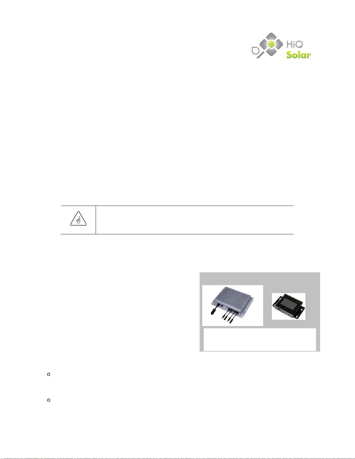
Figure 1
TSXL380-8k-VN and Gateway
Components and Accessories
One TSXL380-8k-VN inverter connects to up to 2 strings of PV modules. It also connects to the three-phase, 380V /
50Hz AC-compatible utility connection on the installation site. The TrueString inverter is a non-isolated inverter for use
with ungrounded DC systems.
Multiple inverter outputs may be connected in parallel using the splice box ACSPL-60.
One Gateway module connects to a 220V / 50Hz AC line-to-neutral branch of the utility connection used for the
TrueString inverter (three-phase, 380V AC-compatible). The Gateway module provides for system monitoring, logging
and control. The Gateway is designed for indoor use only. The gateway is sold separately
Internet access should be provided for the Gateway to enable firmware updates and to provide customer
support functions.
770-00015
8
Introduction
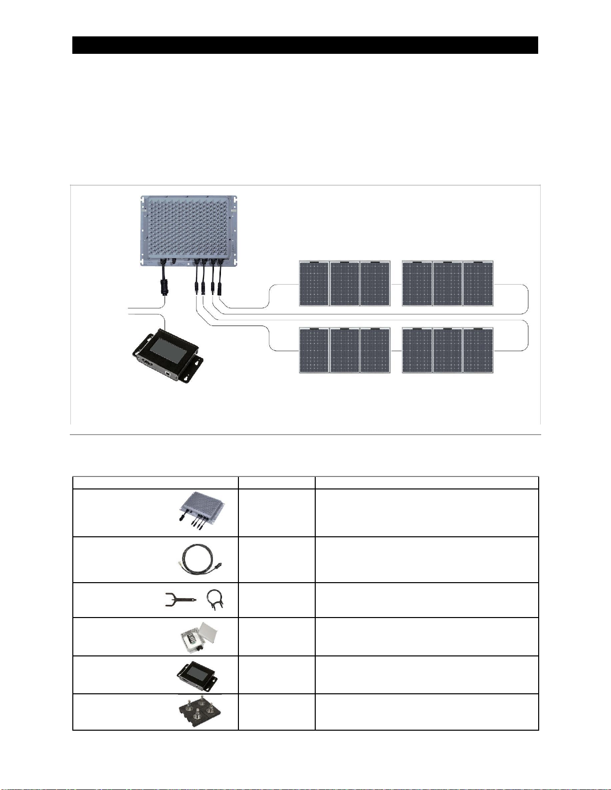
System Overview
The TSXL380-8k-VN is an easy-to-install, modular system which is optimized specifically for commercial
and industrial rooftop, ground mount and car part, parking and shade structures solar array applications.
Unlike other string inverters, each string is individually monitored and managed by the inverter.
A typical layout is shown in Figure 2. It depicts two strings of PV modules supplying a single inverter.
A Gateway is shown connected to one 220V AC phase. Note that while the Gateway provides detailed
reporting and user control, it is optional. The system will generate power without it.
3-phase
String
380V AC
1
1-phase
220V AC
String
using
2
proprietary
277-to-120V
AC adapter
(see below)
Figure 2
Example of System
Table 1
System Ordering and Part Numbers
Item
Part Number
Description
Inverter, 7.9 kW,
TSXL380-8k-VN
Inverter with MC4-compatible connectors (1 each).
380V AC 3-phase
Includes 10-year limited warranty. Does not include
Gateway or AC cable. These two items must be
ordered separately.
480V AC inverter
CBL-480A-05
AC Cable
CBL-480A-15
5 ft, 15 ft, 30 ft, and 50 ft. Each includes one 480V AC
CBL-480A-30
mating connector; the other end is unterminated.
CBL-480A-50
Connector Tools
TOOL-KIT-1
MC4-Compatible Connector Unlatching Tool
(10 each), plus AC Connector Unlatching Tool
(10 each)
AC Splice Box
ACSPL-60
AC combiner splice box, NEMA4 enclosure. Includes
3 gland fittings for up to 3 inverter AC cables.
Inverter AC cables must be ordered separately.
GW-A-277
GW-A Gateway (1 each). Includes 277-to-120V AC
Gateway
adapter and ethernet cable (1 each). Also includes
memory card for logging and storage of results.
Ballast Roof-Mount
MNT-TS1-01
Mounting system for one inverter. Includes mounting
System
feet (4 each) and associated hardware.

770-00015
9
Planning
Design Guidelines
DC Stacking Ratio
The ratio of PV module STC power rating to inverter output power rating is often referred to as “Stacking
Ratio.” Most PV installations are designed for a stacking ratio greater than 1, and less than 1.5. However,
the only real limitations on stacking ratio for the TrueString inverter are the voltage and current limitations
of the string inputs. The full power maximum power point tracking voltage range for the string inputs is
450 to 850V DC. The specified maximum short circuit current of the DC source is 30A DC. However, the
specified stacking ratio is a maximum of 4.0.
A more practical limitation is due to the power and current limits imposed by the inverter firmware. Input
power is limited to 6 kW per string and input current is limited to 12A DC per string.
Ideal stacking ratio varies by installation. For the vast majority of installations, a stacking ratio between
1.1 and 1.5 is acceptable. Under some conditions (constant high irradiance) a lower stacking ratio may
be preferred. A stacking ratio of 1.1 to 1.5 typically allows for energy harvest loss factors such as
module orientation that is less than ideal, inverter efficiency losses, module soiling, module aging, etc.
Still, in some cases a stacking ratio of 1.5 or greater can be advantageous. For example, in the northern
hemisphere a north-facing array, an east- or west-facing array, or high ambient temperatures may justify
a higher stacking ratio.
Also, as PV modules soil and age, their power output decreases. In addition, the STC rating of modules
is typically very optimistic. In reality, most modules produce approximately 85 to 90% of their STC
rating. The system designer is responsible for specifying the string parameters to remain within the
inverter ratings. Simulation software can help determine the best design.
Location
The TrueString is suitable for flat, commercial rooftops, carports, ground mounts, and other commercial
installations. It may be placed using the self-ballasting metal casing. Alternatively, it may be attached to
a PV module frame or roofing component using the provided attachment mechanisms.
Inverter Placement
The TSXL380-8k-VN inverter is NEMA Type 6 rated and may be placed almost anywhere. Cooling is
most efficient if the unit is mounted vertically in the shade, bolted to racking, and with the connectors
pointing downwards. However, any orientation is acceptable.
Clearances
Provide the following minimum space between the inverter and other inverters, or other surfaces.
1” on all sides
4 to 5” from the heat sink (in any direction) to allow air circulation around the cooling fins
1” from the main mounting surface (using the ballast roof-mount system, Unistrut mounting, etc.)
770-00015
10
Introduction
Gateway Placement
Internet access should be provided to enable firmware updates and customer support functions.
CAUTION: Equipment Damage
The Gateway is not rated for outdoor installation.
The Gateway is rated for indoor installation only. Do not expose it to rain, extreme temperatures, or
excessive dust. It must be mounted indoors. A utility closet or similar location physically close to the
inverter system is ideal. If outdoor placement is required, the Gateway must be housed in a weatherproof
enclosure.
The Gateway must be electrically connected to one of the three AC phases used by the inverter. Note that in
large utility closets it is often easy to accidentally connect to an unrelated AC circuit.
The Gateway should be protected by a 15A AC overcurrent protection device (OCPD).
To provide the best power line communication (PLC) signal possible, it may be useful to add a 220V AC
outlet at the earliest entry point in the building. The ideal outlet location would be next to the circuit breaker.
A wired Ethernet network connection must be provided to the Gateway for proper data retrieval.
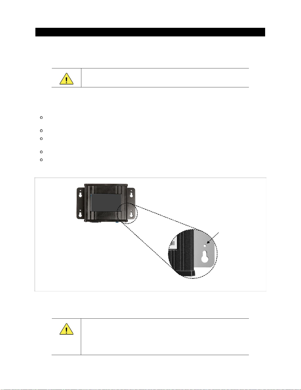
The Gateway has ‘keyhole’ mountings on its baseplate. Each hole has a guide hole. (See Figure 3.) These
four holes can provide a template for mounting such that a pen or center punch can be inserted to mark the
wall and ensure accurate drilling of holes. The Gateway can be mounted using #8 screws.
Guide Hole
Figure 3 Guide Holes
Surge Suppression
CAUTION: Equipment Damage
Depending on physical location, atmospheric effects, utility abnormalities, and local loads,
the utility connection can suffer from repeated disturbances which can damage
equipment. It is recommended that an appropriate surge suppressor be installed near the
point of common connection with the utility. Surge caused damage is not covered by the
warranty terms.

770-00015
11
Installation
The TrueString TSXL380-8k-VN employs industry-standard connection methods. These include
locking interconnects for PV module attachment and standard 5-lead, three-phase AC wiring
compatibility. Make certain to follow all instructions carefully.
Buttons and Indicators
While most installations will use a Gateway to control
and report, it is not mandatory. The TrueString has a
single button with eight LED indicators to give
responses and operating states. The inverter can be
controlled using the button as shown in Table 2. Other
TrueString status messages provided by button
illumination are shown in Table 3 on the next page.
The LED indicators will not become active until the
Figure 4
Button
inverter receives power. See the Connection Outline
section beginning on page 13 for power-up.
Table 2
Inverter Commands (Button)
Inverter Button Press
Button Indication
Result
1 press
Make inverter beep (“are you alive?”)
2 presses
Off & Locked (disabled)
Unit will not begin the 5-minute self-start
3 presses
Start generating immediately
If locked, unlock and generate immediately
If system is faulted, unit will unlock but
will not generate
Long press and Additional Messages:
Long press
“Alternate functions” mode
(>2 seconds)
Ready to accept further button pushes;
this operation times out after 10 seconds
1 press (after
Clear latched faults after (for example)
long press)
an arc-fault test or RCD (residual-current
device) test initiated a fault condition
3 presses (after
RCD-test activation; successful operation
long press)
of RCD test should cause a fault condition
(rapid red flashing) until cleared
4 presses
Arc-fault test activation; successful
(after long
operation of arc-fault detection should
press)
cause a fault condition (rapid red flashing)
until cleared
770-00015
12
Installation
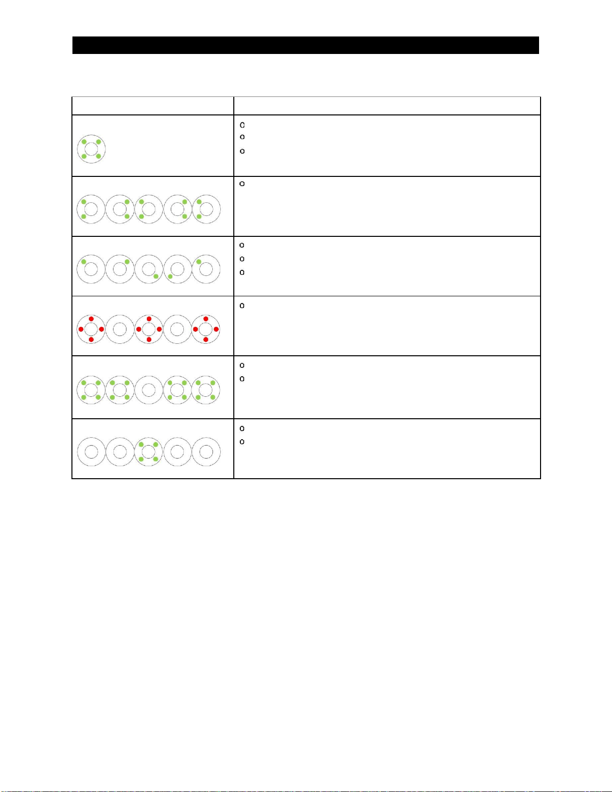
Table 3
Inverter States (Button)
Inverter Indicator State
Button Indication
Green solid
Powered up
Not generating
No faults
Green, left-right alternating flash
Power-on self-test or Grid monitoring
(will take <5 minute)
Green, clockwise circular flash
Powered up
Generating
No faults
Red rapid flash
Fault condition
Examples:
•DC side: RCD or Arc has been detected
•
AC side: Grid voltage or frequency out of range
Green flash, mostly on
Off & Locked
Disabled
Green flash, mostly off
Sleeping
Not generating

770-00015
13
Installation
Connection Outline
CAUTION: Equipment Damage
❖The system must be connected to 380V / 50Hz AC 3-phase wye 5-wire only.
❖The inverter must be provided with an equipment ground according. Do not
apply DC or AC voltage before properly grounding.
❖All five circuits (L1, L2, L3, neutral, ground) must be connected and
neutral must be bonded to earth ground. Failure to do so can damage
the unit and void the warranty.
❖The TrueString inverter has inputs for two separate DC strings. Reversal
of polarity of one or both string inputs or across both inputs will not allow
the unit to operate. Use a voltmeter to carefully verify that the DC inputs
are correct before connecting to the inverter DC inputs.
❖The Gateway is for indoor use only.
❖Do not carry inverter by cables. Damage is not covered by warranty terms.
❖Use best cable installation practices. Do not over stress, tension, or bend cables.
❖In order to maintain the integrity of the watertight enclosures:
✓All connectors must be properly and fully engaged.
✓Unused connectors must be sealed using appropriate weatherproof caps.
✓Do not allow moisture to enter the AC cable wires through the Splice box.
❖Never mate inverter cables that have been left disconnected and
exposed to wet conditions. This voids the warranty.
❖Make certain the Gateway is kept within the specified temperature range of
–20 to +50 °C. In extreme cold conditions, a heater may be needed.
NOTE:
❖Up to five inverters may be connected on the same branch to a single
80A AC OCPD.
❖HiQ offers a NEMA4 AC Splice junction box to connect up to three
inverters. A certified splice box that meets local safety codes must
be used.
❖Perform all electrical installations in accordance with all applicable local
electrical codes.
Connection Order
Make connections in the following order:
A. (Page 14) Connect an equipment ground to the inverter. This step should always be performed first.
B. (Page 15) Connect the inverter to the utility grid, leaving the connection turned off.
C. (Page 17) Connect the PV module strings to the inverter inputs.
D. (Page 18) Turn on the AC source.
E. (Page 19) Connect the Gateway to one 220V AC (line-to-neutral) branch of the same 380V AC
circuit as the inverter and the network. Observe the inverter’s operation.
F. (Page 21) Unlock any inverters that powered up in the Locked Off state.

770-00015
14
Installation
380V AC Wye only —neutral, ground, and three phases
TSXL380-8k-VN
380 Vac
PV String 1
Equipment
ground
Inverter AC cable
PV String 2
220 Vac
AC
Splice
TSXL380-8k-VN
box
380V AC
Dedicated branch
3ph grid
circuit
Additional dedicated
OCPD
branch circuits
Connector is a
means of DC
disconnect
TSXL380-8k-VN
OCPD
Gateway
Connector is a
means of AC
Equipment ground is supplied
disconnect
through AC connector
Figure 5 Example line diagram
Connection Steps
A. Grounding
This connection should always be established before taking any other steps.
To establish a ground connection:
1. Connect the metal enclosure of the inverter to earth ground.
•The equipment ground is provided through the AC
connection. The system may also be grounded using the
mounting bolts to any properly grounded metallic structure.
A paint-cutting washer, such as a stainless steel star
washer, must be used.
•The inverter case may be grounded by connecting
Figure 6
Lay-in Lug
a ground conductor to a lay-in lug (not provided) attached
to the chassis. See Figure 6.
CAUTION: Equipment Damage
Do not connect any DC or AC voltage unless the inverter is properly grounded
770-00015
15
Installation
B. AC Wiring
To connect the inverter to the utility grid:
WARNING: Shock Hazard
This product incorporates high voltages.
CAUTION: Equipment Damage
The neutral must be bonded to earth ground. Failure to do so can damage the unit and
void the warranty. Do not carry unit by cables as it will damage it and void the warranty.
IMPORTANT:
The unit is only watertight when connectors are fully engaged. If connectors are left
unconnected, they must be protected from moisture. Do not tightly bend cables.
NOTE:
The inverter AC cables are TC-ER rated1.
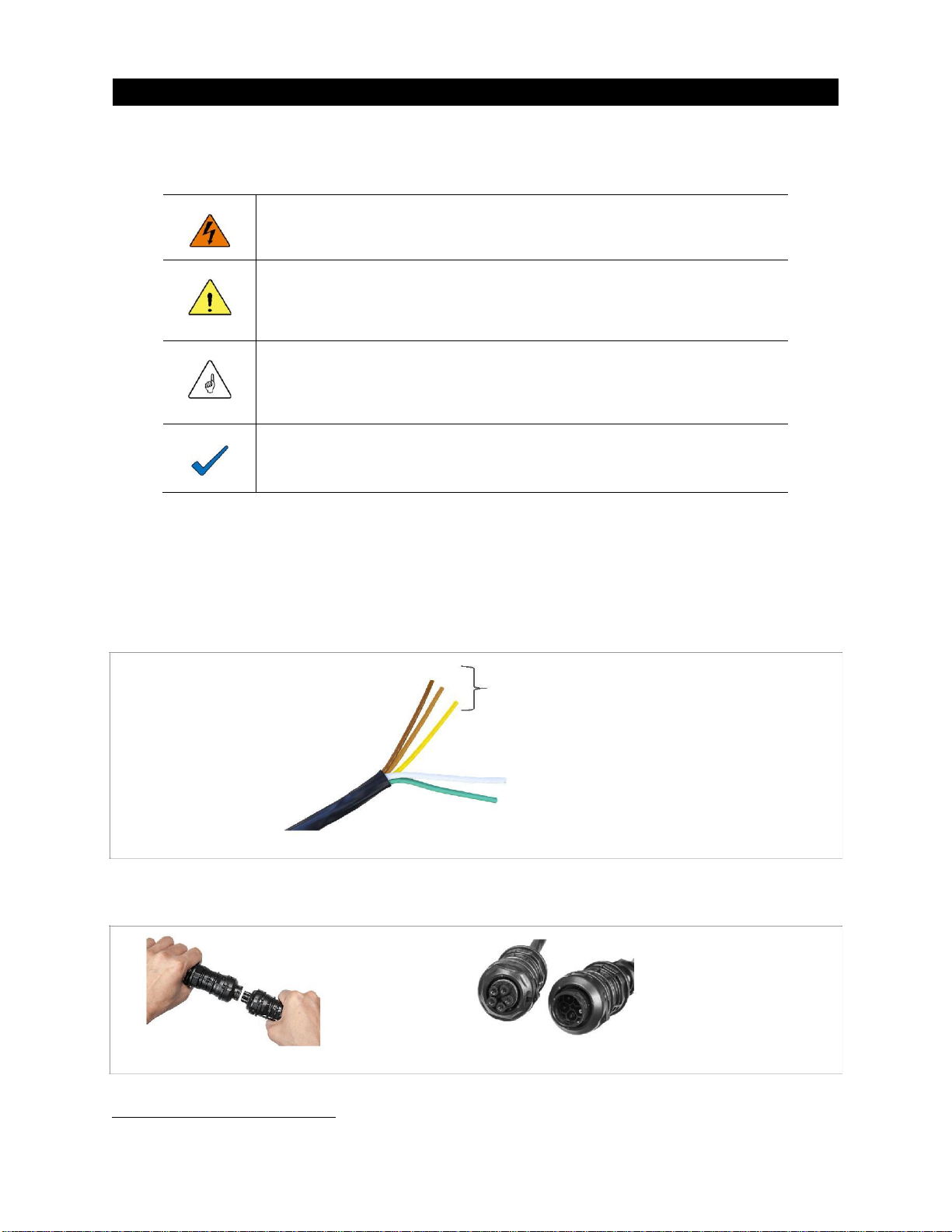
1. Connect the inverter AC cable (sold separately) to the 380V / 50Hz AC circuit. Follow the wiring
conventions shown in Figure 7.
•All five conductors (L1, L2, L3, neutral, ground) must be connected. Note that particular care is
required to ensure that an effective neutral connection is maintained when a transformer is part of
the installation. See page 16.
•The inverter exports power only on the “line” (hot) conductors. The neutral conductor is used
solely for voltage sensing and power line communications.
Any color
to any phase
Grey to neutral
Green to equipment ground
Figure 7 480V AC Cable
2. Connect the inverter to the AC system by connecting the AC cable plug to the inverter plug as shown
in Figure 8. Lock the cable by rotating the collar of the whip cable into the locked position.
Figure 8 Connecting AC Plugs
3. Do not turn on AC power to the inverter until instructed in Step Don page 21.
1The “-ER” signifies that the cable is sufficiently rugged for the NEC (section 336.10) to permit its use as “exposed wiring”.
This refers to wiring not installed in a tray, conduit or other raceway. It must be secured every 6 feet or less and protected
from physical damage.
770-00015
16
Installation
Disconnecting the AC Plugs
1
2
3
Figure 9 Disconnecting AC Plugs
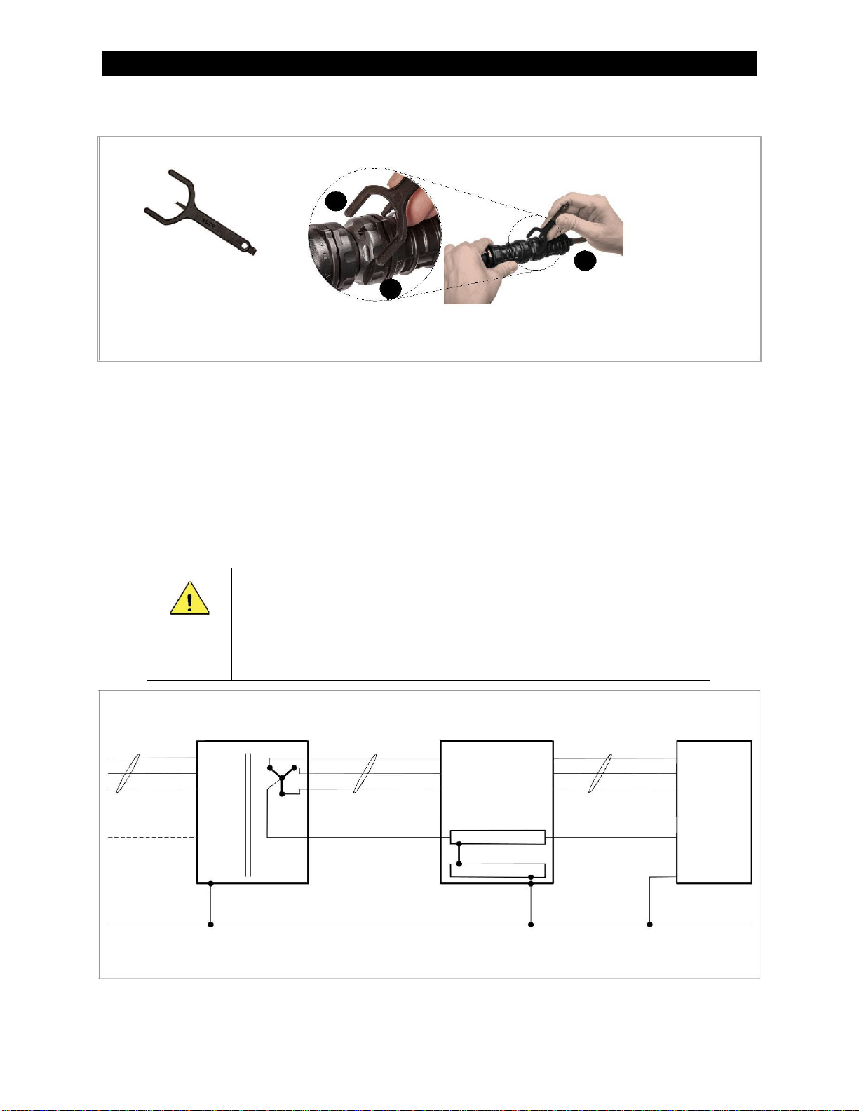
The AC connector can be unlocked by inserting the tool into the whip cable connector hole and rotating
the collar.
The TSXL380-8k-VN comes in a connector-less version for installation locations which have another form
of AC disconnecting means or do not require it, per local electrical codes. For this instance, in addition to
the retaining as mentioned above, the AC cable must be secured within 3 feet of the unit.
Using a Transformer
While TrueString inverters may be used with a transformer, care must be taken to ensure proper wiring.
CAUTION: Equipment Damage
The neutral must remain bonded to earth ground. When an isolating transformer
is inserted into the circuit, the neutral may lose any path to equipment ground
that was provided elsewhere. Make sure a neutral-ground bond is established on
the inverter side of the transformer. An example of bonding in the load center is
shown in Figure 10.
Isolating
Load
TSXL380-8k-VN
L1, L2, L3 phases
Transformer
L1, L2, L3 phases
Center
L1, L2, L3 phases
Inverter
(primary)
(380V AC secondary)
(380V AC)
Utility
Neutral
Neutral
Connection
Neutral Bar
Ground Bar
Equipment Ground
Figure 10 Use of TSXL380-8k-VN with Isolating Transformer
770-00015
17
Installation
C. PV Module Connection
To connect the strings of PV modules:
CAUTION: Equipment Damage
Do not exceed 1000V on the DC inputs. This will cause irreparable damage to the
TrueString inverter and is not covered by the warranty terms. Do not carry unit by
the cables as it will damage it.
IMPORTANT:
The unit is only watertight when connectors are fully engaged. If connectors are left
unconnected, they must be protected from moisture. Do not tightly bend cables.
NOTE:
Connectionmay be made with the AC source on or off. This section assumes
the source is off.
1. Connect the male and female plugs, inserting them together by hand as shown in Figure 11. Make
sure the connectors are fully locked and will not pull apart.
2. With DC voltage present (but AC power turned off), the inverter button will flash red. (See page 11.)
This is normal when no grid is present.
Figure 11 Connecting PV Plugs
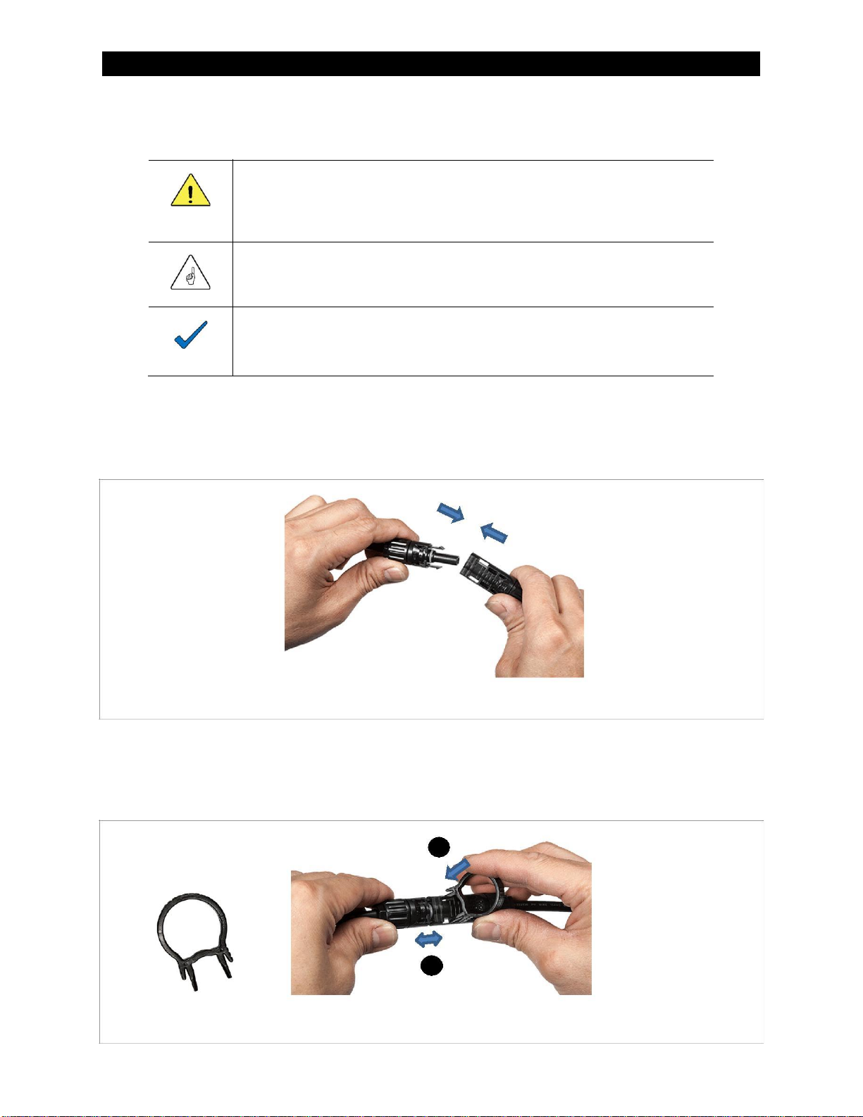
Disconnecting the PV Plugs
1. Use the DC tool to disconnect the male and female connectors. Follow steps 1and 2in Figure 12.
Before disconnecting, make sure there is no current present with a DC clamp meter.
1
2
Figure 12 Disconnecting PV Plugs

770-00015
18
Installation
D. AC Power-Up
To power up the inverter:
1. Turn on the utility grid connection. This starts a 5-minute timer. While this timer runs, the inverter
tests the grid power to ensure all requirements are met. When this timer expires, each inverter will
perform a self-test and then begin generating.
•To skip the 5-minute timer, see page 21.
2. Observe the inverter button LED indicators. (See page 11.) During the wait period, the green lights
will be flashing back and forth. Once the period expires and the inverter begins generating power,
the green lights will flash in a clockwise circular motion.
•This does not apply if the inverter is in the Locked Off state. (See page 21.) In this state, the
TrueString inverter is active but is prohibited from generating power. The locked state is
indicated by all green indicators on and flashing off momentarily repeatedly.
•An individual inverter may be unlocked and turned on to begin generating by pressing the
inverter button three times (Figure 13).
•The Gateway can unlock multiple inverters at the same time. See page 21.
Locked Off
state
Unlocking
Figure 13 Locked Off State

770-00015
19
Installation
E. Gateway Connection
To connect the Gateway:
CAUTION: Equipment Damage
The Gateway is rated for indoor installation only.
NOTE:
The Gateway should be located as near to the inverter(s) as possible
for reliable communication. An electrical connection in the same
subpanel as the inverter branch circuit breakers is recommended.
1. Connect the Gateway 277V to 120V adapter cable to one 220V AC (line-to-neutral) branch of the
same 380V AC circuit as the inverter and the network. The maximum branch overcurrent protection
is 15A. Plug the adapter cable into the gateway.
2. An Ethernet connection may also be made at this stage.
IMPORTANT:
For correct operation, the SD card
included with the Gateway must be
installed. Gateway communication will
not function without this card. See
pages 26 and 42.
277V to 120V
Adapter Cable
Ethernet cable
Figure 14 Gateway Connections
TrueString
Gateway
Inverter
Load Center
Ethernet cable
Gateway
Single-phase
Grid service
277-to-120V AC
220V AC L-N
cable
Three-phase
380V AC L-L
Additional branch circuit
Three-phase 380V AC L-L
Figure 15 Gateway and TrueString Example
770-00015
20
Installation
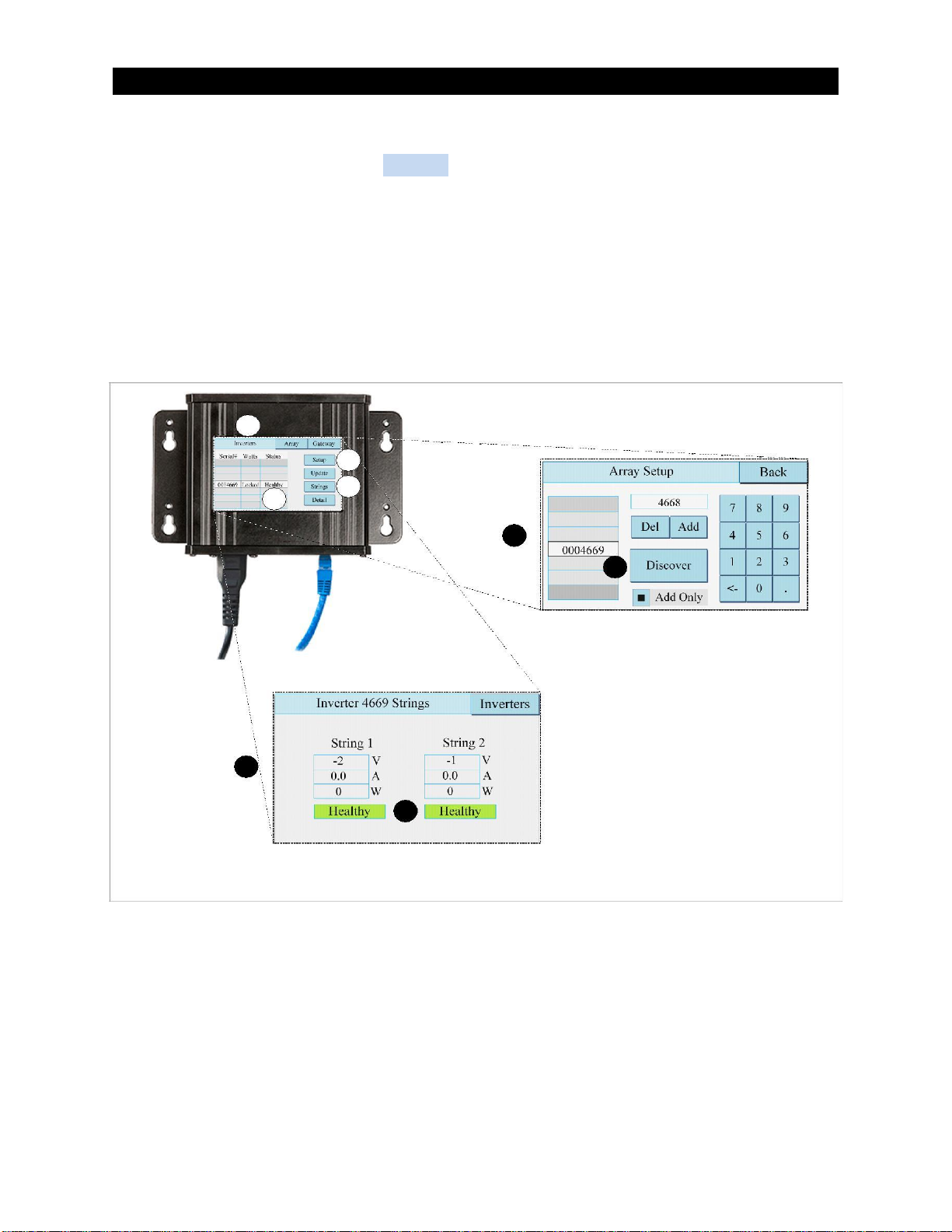
3. Turn on AC power to the Gateway and wait for the screen to illuminate.
4. On the Gateway screen, select the Inverters tab Aat the top of the screen if it is not already
selected. (See Figure 16. Also, see pages 23 and 26 for Gateway navigation and inverter states.)
•To check inverter status, press the Setup button B. On the Array Setup screen, press the
Discover button F. The Gateway will search for all inverters. Confirm that they indicate
Healthy status as shown in C. If the Discover does not find any or some of the inverters, they
can be manually entered by entering the numeric part of the serial number into the box using
the number pad and pressing the Add button.
•To check the status of the PV strings connected to each inverter, press the Strings button D.
On the Inverter Strings screen, confirm that they indicate Healthy status as shown in E.
A
B
D
C
B
F
D
E
Figure 16 Inverter Status
Table of contents
Popular Inverter manuals by other brands

Peak Scientific
Peak Scientific Genius 3040 installation guide

Power One
Power One PVI-5000-6000-OUTD-US manual

GRIDFREE
GRIDFREE BACH KIT installation manual

Somogyi Elektronic
Somogyi Elektronic SAI Series instruction manual

SMA
SMA SUNNY TRIPOWER CORE1-US user manual

Velleman
Velleman SOL30UC12V user manual

SMA
SMA SUNNY BOY STORAGE 2.5 operating manual

Black & Decker
Black & Decker pc 200 manual

Generac Power Systems
Generac Power Systems Magnum Series operating manual

Sony
Sony Tektronix AWG2021 Service manual

Onan
Onan BGM Series Service manual

Mitsubishi Electric
Mitsubishi Electric FR-XCG-K Series instruction manual


