Trust TC Series User manual

TRUST AIR CONDITIONING EQUIPMENT CO.
Prepared By: Engineering & R & D Department.
Shiraz- May 2017
INVERTER WALL MOUNTED SPLIT
(TC SERIES)
TRUST AIR CONDITIONING EQUIPMENT CO.
Prepared By: Engineering & R & D Department.
Shiraz- May 2017

CONTENTS
2016
1.2Connecting the cables................................................................................................................. 1
1.3Pipe lengthand the elevation...................................................................................................... 2
1.4Installation for the first time......................................................................................................... 3
1.5Adding the refrigerant after running the systemfor manyyears.................................................4
1.6Re-installationwhiletheindoor unit need tobe repaired............................................................5
1.7Re-installationwhiletheoutdoor unit need tobe repaired...........................................................6
1 Installation Details..................................................................................................................................1
1.1Wrench torquesheet for installation...............................................................................................1
3.2Displayfunction...........................................................................................................................10
3.3MainProtection........................................................................................................................... 11
3.4OperationModes and Functions.................................................................................................12
3 Electronic function ............................................................................................................................... 10
3.1Abbreviation.................................................................................................................................10
2 Operation Characteristics......................................................................................................................9

Outside diameter Torque Additionaltightening torque
mm inch N.cmN.cm
6.35 1/4 1500(153kgf.cm) 1600(163kgf.cm)
9.52 3/8 2500(255kgf.cm) 2600(265kgf.cm)
12.7 1/2 3500(357kgf.cm) 3600(367kgf.cm)
15.9 5/8 4500(459kgf.cm) 4700(479kgf.cm)
19 3/4 6500(663kgf.cm) 6700(683kgf.cm)
The power cordofconnect shouldbe selectedaccordingtothe following specifications sheet.
Rated current ofappliance Nominalcross-sectionalarea (mm²)
>3and ≤60.75
>6and ≤101
>10 and ≤16 1.5
>16 and ≤25 2.5
The cablesizeand the current ofthe fuse or switch aredetermined bythemaximumcurrent indicated
on the nameplatewhich located on the side panelofthe unit. Pleaserefertothe nameplatebefore
selectingthe cable, fuse and switch.
1.Installation Details
1.1Wrenchtorquesheetfor installation
1.2Connecting thecables
1

Thepipelengthandrefrigerant amount:
Model
Pipesize Standard
length
(m)
Max.
Elevation
B(m)
Max.
Length
A(m)
Additional
refrigerant
(g/m)
Gas Liquid
TMST09HT1I3.34/i(O)4SW1R1N1S 3/8’’
(9.52)
1/4’’
(6.35)
5 10 25 15
TMST12HT1I3.66/i(O)4SW1R1N1S 1/2’’
(
12
.
7
)
1/4’’
(6.35)
5 10 25 15
TMST18HT1I3.52/i(O)4SW1R1N1S 1/2’’
(12.7)
1/4’’
(6.35)
5 20 30 15
TMST24HT1I3.55/i(O)4SW1R1N1S
5/8’’
(15.9)
3/8’’
(9.52)
5 25 50 30
Caution:
The capacitytestisbasedon the standardlengthandthe maximumpermissivelengthisbased on the
systemreliability.
1.3Pipelengthand theelevation
2

Airand moistureinthe refrigerantsystemhave
undesirableeffectsasbelow:
Pressureinthe systemrises.
Operatingcurrent rises.
Cooling or heatingefficiencydrops.
Moistureintherefrigerantcircuitmay
freezeand blockcapillarytubing.
Watermaylead tocorrosion ofpartsinthe
refrigerant system.
Therefore,the indoorunitsand thepipes
between indoorand outdoorunitsmustbe leak
tested and evacuated toremovegas and
moisturefromthe system.
Gas leakcheck(Soap water method):
Applysoap wateroraliquidneutral
detergenton the indoorunitconnections or
outdoorunitconnectionsby asoft brush to
checkforleakage ofthe connecting pointsof
the piping.Ifbubbles comeout, the pipes have
leakage.
1.Airpurging withvacuumpump
1)Completelytighten theflarenutsofthe
indoorandoutdoorunits,confirmthatboth
the 2-wayand 3-wayvalves aresettothe
closed position.
2)Connectthe charge hosewiththe push pin
ofhandlelotothe 3-wayvalves gas service
port.
3)Connectthe charge hose ofhandlehi
connectiontothe vacuumpump.
4) Fullyopen the handle Lo of the manifold
valve.
5) Operate the vacuumpump to evacuate.
6) Make evacuation for 30 minutes and check
whether the compoundmeter indicates
-0.1Mpa. Ifthe meter does not indicate
-0.1Mpa after pumping 30 minutes, it
should be pumped 20 minutes more. Ifthe
pressure can’tachieve -0.1Mpa after
pumping 50 minutes, please checkifthere
are some leakage points.
Fullyclose the handleLo valveofthe manifold
valveand stopthe operation ofthe vacuum
pump.Confirmthatthe gauge needledoesnot
move(approximately5minutes afterturning off
the vacuumpump).
7)Turnthe flarenutof the 3-wayvalves about
45°counterclockwise for6or7seconds
after the gas
coming out, then tighten the flarenutagain.
Makesurethe pressuredisplayinthe pressure
indicatorisalittlehigherthan the atmosphere
pressure.Thenremovethe charge hose from
the 3wayvalve.
8)Fullyopenthe 2wayvalveand3wayvalve
and securelytighten the cap ofthe 3way
valve.
2.Airpurging byrefrigerant
Procedure:
1). Confirmthatboththe 2-wayand 3-wayvalves
areset tothe closed position.
2). Connectthe charge setand acharging
cylinder tothe service portofthe 3-wayvalve.
1.4Installation for thefirsttime
3

3). Air purging.
Open the valves on the charging cylinderandthe
charge set. Purge the airbyloosening the flare
nuton the 2-wayvalveapproximately45’for3
seconds then closing itfor1minute;repeat3
times.
Afterpurging the air,use atorque wrench to
tighten the flarenut on the2-wayvalve.
4). Checkthegas leakage.
Checkthe flareconnections for gas leakage.
5). Dischargethe refrigerant.
Close the valveon the charging cylinderand
dischargethe refrigerantbyloosening the flare
nuton the 2-wayvalveapproximately45’until the
gaugeindicates 0.3to0.5Mpa.
6). Disconnectthe chargesetand the charging
cylinder,and setthe 2-wayand 3-wayvalves to
the open position.
Besuretouse ahexagonalwrench tooperatethe
valvestems.
7). Mountthe valvestemsnutsandthe service
port cap.
Besuretouse atorquewrench totighten the
service port cap toatorque18N m.
Besuretocheckthe gas leakage.
3.Adding therefrigerantif thepipe
length>5m
Procedure:
1). Connectthe charge hose tothe charging
cylinder,open the 2-wayvalveand the 3-way
valve.
Connectthe charge hose which you
disconnected fromthevacuumpumptothe
valveatthe bottomofthe cylinder.Ifthe
refrigerantisR410A,make the cylinderbottom
up toensuretheliquidcharge.
2). Purge the air fromthe charge hose.
Open the valveatthe bottomofthe cylinder
and pressthe checkvalveon the charge setto
purge the air(be carefulofthe liquid
refrigerant).
3)Putthe charging cylinderontothe electronic
scaleand recordthe weight.
4)Operatethe airconditioneratthe cooling
mode.
5)Open the valves (Lowside)onthe chargeset
and charge the systemwithliquidrefrigerant.
6).When the electronicscaledisplaysthe proper
weight(refertothe table), disconnectthe charge
hose fromthe 3-wayvalve’sservice port
immediatelyand turnoffthe airconditionerbefore
disconnecting the hose.
7). Mountthe valvestemcapsand theservice
port
Use torque wrench totighten the serviceport
cap toatorque of18N.m.
Besuretocheckfor gas leakage.
Procedure:
1). Connectthe charge hose tothe 3-wayservice
port, open the 2-wayvalve and the 3-wayvalve.
Connectthe charge hosetothe valveatthe
bottomofthe cylinder.Ifthe refrigerantis
R410A,make the cylinderbottomup toensure
liquidcharge.
2). Purge the air fromthe charge hose.
Open the valveatthe bottomofthe cylinder
1.5Adding therefrigerantafterrunning
thesystemfor manyyears
4

and pressthe checkvalveon the charge setto
purge the air(be carefulofthe liquid
refrigerant).
3)Putthe charging cylinderontothe electronic
scaleand recordthe weight.
4)Operatethe airconditioneratthe cooling
mode.
5)Open the valves (Lowside)onthe chargeset
and charge the systemwithliquidrefrigerant.
6).When the electronicscaledisplaysthe proper
weight (refer tothe gauge and the pressureofthe
lowside), disconnectthechargehose fromthe
3-wayvalve’sservice portimmediatelyand turn
offthe airconditionerbeforedisconnecting the
hose.
7). Mountthe valvestemcapsand theservice
port
Use torque wrench totighten the serviceport
cap toatorque of18N.m.
Besuretocheckfor gas leakage.
1.Collecting therefrigerantintotheoutdoor
unit
Procedure
1). Confirmthatboththe 2-wayand 3-wayvalves
areset tothe opened position
Removethe valvestemcapsand confirmthat the
valvestemsareinthe opened position.
Besuretouse ahexagonalwrenchtooperatethe
valvestems.
2). Connectthe charge hose withthe push pinof
handlelotothe 3-wayvalves gas service port.
3). Air purging ofthe charge hose.
Open the handleLo valveofthemanifoldvalve
slightlytopurge airfromthe chargehosefor5
seconds andthen closeit quickly.
4). Set the 2-wayvalvetothe closeposition.
5). Operatethe airconditioneratthe cooling cycle
and stop it when the gaugeindicates0.1MPa.
6). Setthe 3-wayvalvetothe closedposition
immediately
Dothisquicklyso thatthe gauge ends up
indicating 0.3to0.5Mpa.
Disconnectthe charge set, and tighten the2-way
and 3-wayvalve’sstemnuts.
Use atorquewrench totighten the 3-wayvalves
service port cap toatorqueof18N.m.
Besuretocheckfor gas leakage.
2.Airpurging bytherefrigerant
Procedure:
1). Confirmthatboththe 2-wayand 3-wayvalves
areset tothe closed position.
2). Connectthe charge setand acharging
cylinder tothe service portofthe 3-wayvalve
Leavethe valveon the chargingcylinder closed.
3). Air purging.
Open the valves on the charging cylinderand the
charge set. Purge the airbyloosening the flare
nuton the 2-wayvalveapproximately45’for3
seconds then closing itfor1minute;repeat3
times.
Afterpurging the air,use atorque wrench to
tighten the flarenut on the2-wayvalve.
4). Checkthegas leakage
Checkthe flareconnections for gas leakage.
1.6Re-installation whiletheindoor unit
needtoberepaired
5

5). Dischargethe refrigerant.
Close the valveon thecharging cylinderand
dischargethe refrigerantbyloosening the flare
nuton the 2-wayvalveapproximately45’until the
gaugeindicates 0.3to0.5Mpa.
6). Disconnectthe chargesetand thecharging
cylinder,and setthe 2-wayand 3-wayvalves to
the open position
Besuretouse ahexagonalwrenchtooperatethe
valvestems.
7). Mountthe valvestemsnutsand the service
port cap
Besuretouseatorquewrench totighten the
service port cap toatorque18N.m.
Besuretocheckthe gas leakage.
1.Evacuationfor thewholesystem
Procedure:
1). Confirmthatboththe2-wayand 3-way
valves areset tothe opened position.
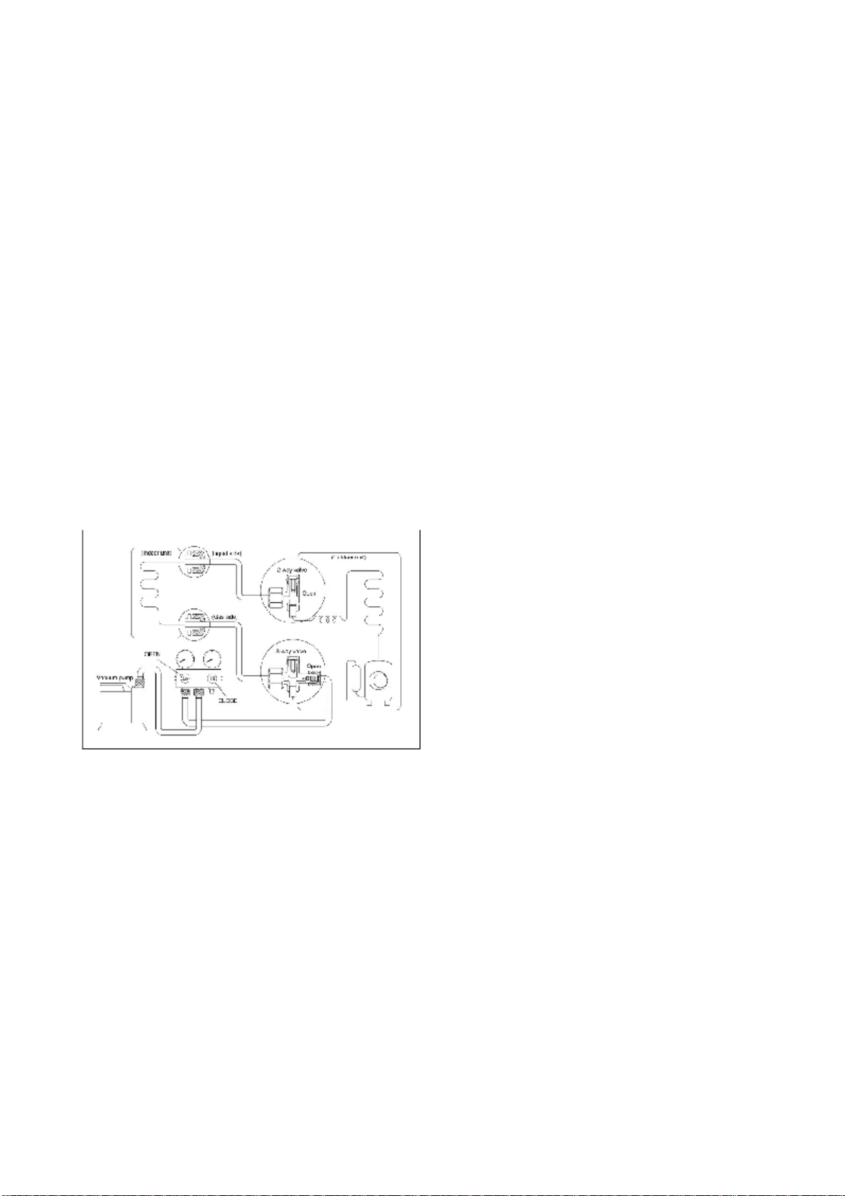
2). Connectthe vacuumpumpto3-wayvalve’s
service port.
3). Evacuation forapproximatelyone hour.
Confirmthatthe compound meterindicates
-0.1Mpa.
4). Close the valve(Lowside)on the charge set,
turnoffthe vacuumpump,and confirmthatthe
gaugeneedledoes notmove(approximately5
minutesafter turningoffthe vacuumpump).
5). Disconnectthe chargehose fromthe vacuum
pump.
2.Refrigerant charging
Procedure:
1). Connectthe charge hose tothe charging
cylinder,open the 2-wayvalveand the 3-way
valve
Connectthe charge hose which you
disconnected fromthevacuumpumptothe
valveatthe bottomofthe cylinder.Ifthe
refrigerantisR410A,make the cylinderbottom
up toensureliquidcharge.
2). Purge the air fromthe charge hose
Open the valveatthe bottomofthe cylinder
and pressthe checkvalveon the charge setto
purge the air(be carefulofthe liquid
refrigerant).
3)Putthe charging cylinderontothe electronic
scaleand recordthe weight.
4). Open the valves (Lowside)on the chargeset
and charge the systemwithliquidrefrigerant
Ifthe systemcannotbe charge withthe specified
amountofrefrigerant, orcan be charged witha
littleatatime(approximately150g each time),
operating theairconditionerinthe cooling cycle;
however,one timeisnotsufficient, wait
approximately1minuteand then repeatthe
procedure.
5).When the electronicscaledisplaysthe proper
weight, disconnectthe chargehosefromthe
3-wayvalve’sservice port immediately
Ifthe systemhas beenchargedwithliquid
refrigerantwhileoperatingthe airconditioner,
turnoffthe airconditionerbeforedisconnecting
the hose.
6). Mountedthe valvestemcapsandthe service
1.7Re-installation whiletheoutdoor unit
needtoberepaired
6

port. Use torque wrench totighten the service
port cap toatorque of18N.m.
Besuretocheckfor gas leakage.
7

Mode
Temperature
Cooling operation Heating operationDrying operation
Roomtemperature 17℃~32℃
(62℉~90℉) 0℃~30℃
(32℉~86℉) 10℃~32℃
(50℉~90℉)
Outdoortemperature
0℃~50℃
(32℉~122℉) -15℃~30℃
(5℉~86℉)0℃~50℃
(32℉~122℉)
-15℃~50℃(5℉~122℉)
(For the modelswithlow
temperaturecoolingsystem)
CAUTION:
1. Ifthe airconditionerisused beyond the aboveconditions,certainsafetyprotectionfeatures
maycomeintooperationand cause the unit tooperateabnormally.
2.The roomrelativehumidityshouldbeless than80%. Ifthe air conditioner operates beyondthis
figure,the surface oftheairconditionermayattractcondensation.Pleasesetthe verticalairflow
louver toitsmaximumangle(verticallytothe floor), and set HIGHfan mode.
3.The optimumperformance will be achieved duringthisoperatingtemperaturezone.
2.Operation Characteristics
8

T1:Indoor roomtemperature
T2:Coil temperatureofevaporator
T3:Coil temperatureofcondenser
T4:Outdoor ambient temperature
T5:Compressor discharge temperature
Digitaldisplay:
Displaysthe temperaturesettings whenthe air
conditioner isoperational.
Displaysthe roomtemperatureinFANmode.
Displaysthe self-diagnosticcodes.
Dispalys ‘ ’ forthreeseconds whenTimer
ON,Fresh,Swing,TurboorSilence featureis
activated.
Dispalys ‘ ’ forthreeseconds when Timer
OFF ,Fresh,Swing,TurboorSilence featureis
cancelled.
Dispalys ‘ ’ under deforstingoperation.
Dispalys ‘ ’ whenanti-coldairfeatureis
activated under heating mode.
Dispalys ‘ ’ duringself clean operation(if
aplicable).
Dispalys ‘ ’ under8 heating operation (if
aplicable).
(Optional)
According tothe operation mode,the””
indicator displaysdifferentcolour:
UnderCoolorDrymode,itdisplaysas cool
colour.
Under Heat mode,it displaysas warmcolour.
(ifaplicable)
Energysaving display:
Displayswhen the energysacing featureis
activated.(Notavailablewhen the unitdoes not
haveenergysaving mode.)
(Optional)
WIFI controldisplay:
Displaywhen theWIFIcontrolfeatureis
activated. (Not availablewhen the unit does not
havethisfunction.)
8.2.1Icon explanationon indoor displayboard.
3.Electronicfunction
3.1Abbreviation
3.2Displayfunction
9

compressor
1minutedelayfor the 1st timestart-up and 3
3.3MainProtection
3.3.1Threeminutes delay at restart for
minutesdelayfor others.
3.3.2Temperatureprotection of compressor
top
The unit will stop workingwhen the compressor
top temp. protector cut off,and willrestart after
the compressor top temp.protector restart.
3.3.3Temperatureprotection of compressor
discharge
Compressordischarge temp.T5>115℃for5s,
compressor stops.
3.3.4Fanspeedisout ofcontrol
Whenindoor fan speed keepstoo low
(300RPM) forcertaintime,the unit will stop and
the LEDwilldisplaythe failure
3.3.5Invertermoduleprotection
The Inverter modulehasaprotection function
aboutcurrent, voltage andtemperature.Ifthese
protections happen, the corresponding code
will displayon indoor unitand the unit willstop
working.
3.3.6Indoorfandelayedopenfunction
Whenthe unitstartsup,thelouverwillbeactive
immediatelyand the indoor fan will open 7s
later.
Ifthe unit runs inheatingmode, the indoorfan
will be also controlled byanti-coldwind
function.
3.3.7Compressorpreheating functions
Preheatingpermitting condition:
WhenT4(outdoor ambient temperature)<3°C,
the preheating functionwillbe activated.
3.3.8Sensorprotection atopencircuit and
breaking disconnection.
Whenthere’sonlyone temperaturesensor in
malfunction, the air conditioner willkeep
working but show the error code, incase ofany
emergencyuse.
Whenthere’smorethan one temperature
sensorinmalfunction,the airconditionerwill
stop working.
3.3.9Refrigerant leakagedetection
Thisfunctionisonlyactiveincoolingmode.It
can betterpreventthe compressorbeing
damaged byrefrigerantleakageorcompressor
overload.
Open condition:
Whencompressorisactive,the value ofthe
Coil temperatureofevaporatorT2has no
change or verylittlechange.
3.3.10 Zerocrossing detection error
protection
IfACdetectstimeintervalisnotcorrectfor
continuous240s,the unitwill stop andthe LED
will displaythe failure.The correctzero
crossing signal timeinterval shouldbebetween
6-13ms.
10

abcd
T1
e
WhenT1-Ts<ΔT-2℃, the compressor will stop,
when T1—Ts>ΔT-0.5℃,the compressor will
be activated.
ΔTisthe programmedparameter of
temperaturecompensation.
WhentheAC runinmutemode, the
compressor will run withlow frequency.
Whenthe current ismorethan settingvalue,
the current protection function will be activated,
and the compressor willstop.
The outdoorunitwillberun atdifferentfan
speedaccording toT4.
For different outdoor units, the fan speeds are
different.
High
Low
Setting fan
speed Actualfan speed
H+(H+=H+G)
A H(=H)
B
C
M+(M+=M+Z)
D M(M=M)
E
F
L+(L+=L+D)
G L(L=L)
H
I
T1-Td
℃
(°F)
L
L-(L-=L-D)
H
H-(H-=H-G)
M
M-(M-=M-Z)
The autofanactsas below rules:
abcd
T1
e
Resume
Off
Decrease
Hold
Increase
3.4Operation Modesand Functions
3.4.1Fanmode
(1)Outdoorfanand compressorstop.
(2)Temperaturesettingfunction isdisabled,
and no settingtemperatureisdisplayed.
(3)Indoorfan canbe setto
high/med/low/auto.
(4)Thelouver operates sameasincooling
mode.
(5)Autofan:3.4.2.3Indoorfanrunningrules
Incooling mode, indoorfanruns allthe time
and the speed can be selected as high,
medium, low andauto.
The indoor faniscontrolledas below:
3.4.2Cooling Mode
3.4.2.1Compressorrunning rules
3.4.2.2Outdoorfanrunning rules 3.4.2.4Condensertemperatureprotection
T3
11

Whencondensertemperaturetemp.ismore
than settingvalue, the compressor will stop.
WhenT1-Ts>-ΔT, the compressor will stop,
when T1-TS<ΔT-1.5,the compressorwill be on.
ΔTisthe programmedparameter of
temperaturecompensation.
WhentheAC runinmutemode, the
compressor will run withlow frequency.
Whenthe current ismorethan settingvalue,
the current protection function will be activated
and the compressor willstop.
The outdoorunitwillberun atdifferentfan
speedaccording toT4.
For different outdoor units, the fan speeds are
different.
Low
High
Whenthe compressorison,the indoorfan can
be settohigh/med/low/auto.And the anti-cold
wind function has the priority.
The indoor faniscontrolledas below:
Setting fan
speed Actualfan speed
H+(H+=H+G)
A H(=H)
B
C
M+(M+=M+Z)
D M(M=M)
E
F
L+(L+=L+D)
G L(L=L)
H
I
T1-Td
℃
(°F)
L
L-(L-=L-D)
H
H-(H-=H-G)
M
M-(M-=M-Z)
Autofan action inheating mode:
abcd
T1
e
lighted .“.”Willbe displayed.
If anyone of the followingitemsissatisfied,the
defrostingwill finish andthemachinewillturnto
normalheating mode.
----T3rises tobe higher than TCDE1℃.
----T3keepstobe higherthan TCDE2℃for80
seconds.
----The machinehas run for 15 minutes in
defrostingmode.
3.4.2.5Evaporatortemperatureprotection
WhenEvaporatortemperaturetemp.isless
than settingvalue, the compressor will stop.
3.4.3Heating Mode
3.4.3.1Compressorrunning rules
3.4.3.2Outdoorfanrunning rules
3.4.3.4Defrostingmode
AC willenterthe defrosting modeaccording to
the value oftemp.ofT3and the value range of
temp.change ofT3andalsothe compressor
running time.
During thedefrosting mode, the compressorkeep
running, indoor and outdoor motor will stop,
defrost lampofthe indoor unit will be
3.4.3.3Indoorfanrunningrules
3.4.3.5Evaporatorcoil temperature
protection
12

TEstop
T2
Resume
Off
Decrease
TEdown
TEH2 Hold
Off: Compressor stops.
Decrease:Decrease the running frequencyto
the lower level.
Hold: Keep the current frequency.
Resume: Nolimitation forfrequency.
ΔT=T1-Ts Running mode
ΔT>2℃Cooling
-2≤ΔT≤2℃Fan-only
ΔT<-2℃Heating
Indoorfanwill runatautofan oftherelevant
mode.
The louver operatessameas inrelevant mode.
Ifthe machine switches mode between heating
and cooling, the compressor will keep stopping
for 15 minutesand thenchoosemode
accordingtoT1-Ts.
Ifthe setting temperatureismodified, the
machine will choose running function again.
incooling mode.
3.4.6Forcedoperation function
Forcedcooling mode:
The compressorand outdoorfan keep running
and the indoorfan runsatlowspeed.After
running for30 minutes,AC willturntoauto
mode with24℃setting temperature.
Forcedautomode:
The action offorcedautomode isthe sameas
normalautomode with24℃setting
temperature.
When ACreceives signals,such as switch on,
switch off,timeron,timeroff,mode setting,fan
speedsetting, sleeping mode setting, followme
setting, it willquit the forced operation.
3.4.4Auto-mode
Thismode can be chosenwithremote
controller andthe settingtemperaturecan be
changed between 17°C~30°C
Inautomode, the machinewillchoose cooling,
heating or fan-onlymode accordingto ΔT(ΔT
=T1-Ts).
3.4.5Drying mode
Indoorfanspeed isfixed atbreezeand can’tbe
changed.Thelouverangleisthe sameas in
coolingmode.
Allprotections areactiveand the sameas that
3.4.7Timerfunction
3.4.7.1Timing range is24hours.
3.4.7.2Timeron.The machine willturnon
automaticallywhen reaching the settingtime.
3.4.7.3Timeroff.The machine will turnoff
automaticallywhen reaching the settingtime.
3.4.7.4Timeron/off.Themachine will turnon
automaticallywhen reachingthe setting “on”
time,and then turnoffautomaticallywhen
reaching the setting “off”time.
3.4.7.5Timeroff/on.The machine willturnoff
automaticallywhen reachingthe setting “off”
time,and then turnon automaticallywhen
reaching the setting “on”time.
3.4.7.6The timerfunctionwillnotchangethe
AC currentoperation mode.SupposeACisoff
now,itwill notstart up firstlyaftersetting the
“timeroff”function.And when reaching the
setting time,the timerLEDwillbe offand the
AC running mode hasnot been changed.
3.4.7.7The settingtimeisrelativetime.
3.4.7.8The AC will quitthe timerfunction when
it has malfunction.
3.4.8Economyfunction
3.4.8.1The sleep function isavailablein
cooling, heating or automode.
3.4.8.2.Operationprocessinsleepmodeisas
13

ofthe louver.Duringoperation,ifthe powerfails
orthe end usershutsdownthe unitintheturbo
mode,the louverwill restoretothedefault
angle.
Forheatpumpmodelswhich areprovided with
thisfunction,afterrunningincooling ordrying
mode,ifthe userpress “Self Clean”button on
remotecontroller,firstly,indoorunitruns infan
onlymodeforawhile,then lowheatoperation
and finallyruns infan onlyagain.Thisfunction
can keep the inside ofindoorunitdryand
prevent breeding ofmold.
1)Ifthe indoor PCBreceivesthe signalwhich
resultsfrompressingtheFOLLOWMEbutton
on remotecontroller,the buzzerwill emita
soundand thisindicates the followmefunction
isinitiated.Butwhen the indoorPCBreceives
signalwhich sentfromremotecontrollerevery
3minutes,the buzzerwill notrespond.When
the unitisrunning withfollowmefunction,the
PCBwill controlthe unitaccordingtothe
temperaturefromfollowmesignal,andthe
temperaturecollection function ofroom
temperaturesensorwillbe shielded,butthe
errordetectivefunctionofroomtemperature
sensor willbe still valid.
2)Whenthe follow mefunction isavailable,
the PCBwillcontrolthe unitaccording tothe
roomtemperaturefromthe remotecontroller
and the setting temperature.
3)The PCBwill take action tothe mode
change information fromremotecontroller
follow:
Whencooling,the setting temperaturerises 1℃
(be lowerthan 30℃)everyone hour,2hours
laterthe settingtemperaturestopsrising and
the indoor fanisfixed at low speed.
Whenheating,the setting temperature
decreases 1℃(be higher than 17℃)everyone
hour,2hourslaterthesetting temperature
stopsrisingand indoor fanisfixedat low speed.
(Anti-coldwind function has the priority).
3.4.8.3Operation timeinsleepmodeis7hours.
After7hoursthe ACquitsthismode and turns
off.
3.4.8.4Timer setting isavailable
3.4.9Auto-Restart function
The indoorunitisequipped withauto-restart
function,whichiscarried outthroughan
auto-restart module.Incase of asuddenpower
failure,the modulememorizes the setting
conditions beforethepowerfailure.The unitwill
resumethe previousoperationsetting (not
includingswing function)automaticallyafter3
minuteswhen power returns.
Ifthe memorization condition isforced cooling
mode,the unitwillrun incooling modefor30
minutesand turntoautomode as 24℃setting
temp.
IfAC isoffbeforepoweroffandACisrequired
tostart up now,the compressorwill have1
minutedelaywhen poweron.Otherconditions,
the compressorwill have3minutes delaywhen
restarts.
3.4.10 Refrigerant LeakageDetection
Withthisnewtechnology,the displayarea will
show “EC”when the outdoorunitdetects
refrigerant leakage.
3.4.11LouverPosition MemoryFunction
Whenstarting the unitagainaftershuttingdown,
itslouverwillrestoretotheangleoriginallyset
bythe user,butthe preconditionisthatthe
anglemustbe withintheallowablerange,if it
exceeds,itwillmemorize the maximumangle
3.4.12 8 Heating(optional)
Inheating operation,thepresettemperatureof
the airconditionercan be as loweras 8℃,
which keepsthe roomtemperaturesteadyat
8℃and preventshouseholdthings freezing
when the house isunoccupiedforalong timein
severecoldweather.
3.4.13 Self clean(optional)
3.4.14 Followme(optional)
14

signal,butitwillnotaffected bythe setting
temperature.
4)Whenthe unit isrunning withfollow me
function,if the PCB doesn’treceiveanysignal
fromremotecontrollerfor7minutes orpressing
FOLLOWMEbutton again,the followme
functionwill be turnedoffautomatically, and the
temperaturewill controlthe unitaccording to
the roomtemperaturedetected fromitsown
roomtemperaturesensorandsetting
temperature.
Press the “silence”buttonon remotecontroller
toinitiateSILENCEfunction.When theSilence
functionisactivated,the compressorrunning
frequencywillkeep lowerthan F2and the
indoorunitwillbring faintbreeze,whichwill
reduce the noisetothe lowestleveland create
aquiet and comfortableroomfor you.
3.4.15 Silence operation(optional)
15

Enquiryinformation Displayingcode
Meaning
T1 T1 T1 temp.
T2 T2 T2 temp.
T3 T3 T3 temp.
T4 T4 T4 temp.
T2B Tb T2Btemp.
TP TP TPtemp.
TH TH TH temp.
Targeted Frequency FT Targeted Frequency
ActualFrequencyFr ActualFrequency
Indoorfan speed IF Indoorfan speed
Outdoorfan speed OF Outdoorfan speed
EXVopening angle LA EXVopening angle
Compressorcontinuousrunning time CT Compressorcontinuous
running time
Causesofcompressorstop. ST Causesofcompressor
stop.
ReserveA0
Reserve A1
Reserve 0
Reserve 1
Reserve 2
Reserve 3
Reserve 4
Reserve 5
Reserve 6
Reserve L
Reserve A
Reserve U
Reserve T
When theAC enter into the information enquirystatus, itwill display the code value in the next 25s,
the details are as follows.
3.4.16 Point check function
Press the LEDDISPLAYorLED orMUTEbutton ofthe remotecontrollerthree times,and then press
the AIRDIRECTIONorSWING button three times inten seconds,the buzzerwill keepringfortwo
seconds.Theairconditionerwillenterintothe informationenquirystatus.You can press the LED
DISPLAYorAIRDIRECTIONbutton tocheckthe next or front item’sinformation.
Whenthe ACenterthe “informationenquiry”status,itwill displaythe code namein2seconds,the
detailsareas follows.
16

Enquiry
information Displayvalue MeaningRemark
T1,T2,T3,T4,
T2B,TP,TH,
Targeted
Frequency,
Actual
Frequency
-1F,-1E,-1d,-1c,-
1b,-1A-25,-24,-23,-22,-21,-2
01. Allthe displayingtemperatureisactual
value.
2. Allthe temperatureis °Cno matterwhat
kind ofremote controllerisused.
3. T1,T2,T3,T4,T2Bdisplayrange:-25~70,
TPdisplayrange:-20~130.
4. Frequencydisplayrange: 0~159HZ.
5. Ifthe actualvalue exceedsthe range,it
willdisplaythe maximumvalue orminimum
value.
-19—99-19—99
A0,A1,…A9 100,101,…109
b0,b1,…b9 110,111,…119
c0,c1,…c9 120,121,…129
d0,d1,…d9 130,131,…139
E0,E1,…E9 140,141,…149
F0,F1,…F9 150,151,…159
Indoorfan
speed
/Outdoorfan
speed
0 OFF
1,2,3,4 Lowspeed, Medium
speed, High speed,
Turbo
Forsome big capacitymotors.
14-FF Actualfan
speed=Displayvalue
turnsto decimal
value andthen
multiply10.The unit
isRPM.
Forsome small capacitymotors,
displayvalue isfrom14-FF(hexadecimal),
the corresponding fan speed range isfrom
200-2550RPM.
EXVopening
angle 0-FF ActualEXVopening
value=Displayvalue
turnsto decimal
value andthen
multiply2.
Compressor
continuous
running time
0-FF 0-255 minutesIfthe actualvalue exceedsthe
range, itwill displaythe maximum
value orminimumvalue.
Causesof
compressor
stop.
0-99Forthe detailed
meaning, please
consultwithengineer
Decimaldisplay
Reserve0-FF
17

TRUST AIR-CONDITIONING EQUIPMENT CO.
Shiraz office: 8 th floor, Alvand Blog., Dostan St.,
Moaliabad Ave., SHIRAZ, IRAN., Post code: 71877-14446
Tel.: +98-71-36341070
Fax.: +98-71-36341094
Tehran office: No. 19- koohe nour St.- Motahhari St.-
TEHRAN, IRAN., Post code: 15876-73111
Tel.: +98-21-89389
Fax.: +98-21-88541903
Ahwaz office: No. 309- Kaveh St.- AHWAZ, IRAN., Post code: 61939-
47911
Tel.: +98-61-32230647-8
Fax.: +98-61-32230647
E-mail: info@trustacs.com
Web site: http://www.trustacs.com
Air Conditioning Systems
Cooling & Heating
Table of contents
Other Trust Air Conditioner manuals
Popular Air Conditioner manuals by other brands

Olimpia splendid
Olimpia splendid maeStro Pro Instructions for installation, use and maintenance

Frigidaire
Frigidaire FFRE0533S1E0 Use & care guide

NuAire
NuAire UNI-X Series installation manual

Cooler Master
Cooler Master Silent Pro Gold 450W user manual

Hitachi
Hitachi RAK-18QXD Service manual

Mitsubishi Electric
Mitsubishi Electric MSC-GE20VB operating instructions