TruTalk MURS-22 User manual

COMPANY NAME:VERTEX STANDARD CO., LTD.
EUT: MURS-22 VHF
WORK ORDER NUMBER:2001083
FCC ID: O7KMURS22
Page 41 of 63
22 OPERATOR’S MANUAL
Please see the following page
MURS-22
Operating Instructions


About Topaz3
Topaz3 is the exclusive supplier of Maxon®, Legacy
and TruTalk brand communication products.
Our Business and Industry product line ranges from FCC
licensed two-way radios suitable for markets like farm,
government, law enforcement, utility, etc. to consumer
recreational and light-duty business markets.
Product offerings include a variety of UHF and VHF
handheld and mobile radios, repeaters and RF link
modules as well as FRS (Family Radio Service), GMRS
(General Mobile Radio Service) radios, Citizen’s Band
radios and weather monitors.
Available accessory items include: a variety of carrying
cases, spare batteries, desktop and mobile chargers,
ear bud speaker microphones, and more for each radio
model.
For additional information on our product line, visit our
website:
www.topaz3.com

Table of Contents / Contenido
I. FCC RF Exposure Compliance Requirements -
for Occupational Use Only.............. .1
I.
Requerimientos de Obediencia a la
Exposición de RF del FCC - para uso
Ocupacional Solamente ..........................27
II. Unpacking and Checking Equipment......3
II. Desempaque y Verificación del Equipo..........29
III. Getting Started.......................................4
III. Preparación..................................................30
Charging the NiMH Battery Pack............4
Cargador de la Batería de NiMH....................30
Attaching and Removing the Battery Pack.6
Instalación y Retiro de la Batería.....................32
Installing the Antenna......................... 7
Instalación de la Antena..............................33
Installing the Belt Clip..........................7
Instalación del Clip de Cinturón....................33
Installing the Speaker Mic. Jack Cover.......7
Instalación de la Cubierta de la Clavija
de Conexión de Micrófono del Altavoz.............34
Attaching the Optional Speaker Mic..........8
Agregando el Micrófono de Altavoz Opcional ..34
IV. Control Buttons / Operation Features.....9
IV. Botones de Control del Radio / Rasgos
de Funcionamiento...................................... 35
V. Radio Operation...................................10
V. Funcionamiento del Radio............................ 36
Power On / Transmit...........................10
Encienda / Transmite...................................36
VI. Channel Frequency Selection................ 11
VI. Selección de Frecuencia de Canales.............. 37

VII. CTCSS Tone Signaling............................13
VII. Señal de Tonos de CTCSS.............................40
VIII. CTCSS Tone Setup.................................14
VIII. Arreglo de Tonos de CTCSS
..........................
41
IX. Channel Setting Confirmation..................17
IX. Confirmación de la Configuración
de Canal.................................................45
Frequency Confirmation
........................
17
Confirmación de la Frecuencia.....................45
CTCSS Tone Confirmation
..................
.....18
Confirmación de Tonos de CTCSS.................45
X. Radio Functions.....................................19
X. Funciones del Radio.....................................46
Time-Out-Timer (T-O-T)..................................19
Temporizador de Tiempo Límite (T-O-T)..........46
Battery Save......................................................19
Preservación de Batería...............................47
Low Battery Warning
.............................
19
Aviso de Batería Baja..................................47
XI. Licensing, Safety and Service Information.20
XI. Información de Autorización y Servicio..........48
FCC Licensing.................................... 20
Licencia de la FCC.....................................48
Safety Information................................20
Información de Seguridad............................48
Service..............................................21
Servicio....................................................... 49
XII. Maintenance......................................... 21
XII. Mantenimiento............................................49
XIII. Software Copyrights...............................22
XIII. Derechos de Propiedad Literaria del Software..50
XIV. Topaz3 / Legacy Product Warranty...........23
XIV. Garantía del Producto de Topaz3 / Legacy...... 51

I. FCC RF Exposure Compliance Requirements -
for Occupational Use Only
The Federal Communications Commission (FCC), with
its action in General Docket 93-62, November 7, 1997,
has adopted a safety standard for human exposure to
Radio Frequency (RF) electromagnetic energy emitted
by FCC regulated equipment. Topaz3 / TruTalk
subscribes to the same safety standard for the use of its
products. Proper operation of this radio will result in user
exposure far below the Occupational Safety and Health
Act (OSHA) and Federal Communications Commission
limits.
CAUTION - DO NOT transmit for more than 50% of total
radio use time (50% duty cycle). Transmitting
more than 50% of the time can cause FCC
RF exposure compliance requirements to be
exceeded.
•When transmitting, hold the radio in a vertical position
with its microphone 2 inches (5 cm) away from your
mouth. Keep the antenna at least 2 inches (5 cm) from
your head and body.
•This device has been approved for use, at a maximum
duty factor of 50%, using the specific belt clip tested for
body-worn SAR compliance. Other belt clips or body-
worn accessories may not comply and should be
avoided. ALWAYS use Maxon, Legacy and TruTalk
authorized accessories: antennas, batteries, belt clips,
1

I. FCC RF Exposure Compliance Requirements -
for Occupational Use Only, continued
•The radio is transmitting when the red LED on the
front of the radio is illuminated. You can cause the radio
to transmit by pressing the P-T-T bar on the radio.
•These are required operating configurations for meeting
FCC RF exposure compliance. Failure to observe these
restrictions mean violation.
2

II. Unpacking and Checking Equipment
Carefully unpack the radio and its accessories. Use
the item list below to identify the components included
in the product packaging, to ensure that no items are
discarded in the packing materials.
Radio Body
Antenna
Battery Charger (with plastic spacer
stored in charger base)
AC Adapter
NiMH Battery Pack
Speaker Microphone Jack Cover
Belt Clip
Screw Set
Operating Instructions
If any items are missing or damaged, you should
contact the Topaz3 Customer Service Department.
Dial 1-800-821-7848, Ext. 499 for assistance.
3

III. Getting Started
Charging the NiMH Battery Pack
You will need to charge the battery pack fully before
initial use. For best results from your charging cycle,
follow these tips:
•Ensure the ambient temperature is between 41 and
104° F (5 and 40° C) while charging. Temperatures
outside this range may not fully charge the battery.
• Always switch OFF the transceiver equipped with
a NiMH battery pack before charging. Using the
radio during the charging cycle will hinder correct
charging.
• Do not recharge the battery pack if it is already
fully charged. Doing so may cause the life of the
battery pack to shorten or the battery pack may
be damaged.
• If the battery is stored for 2 months or more, it is a
good idea to complete the charge / discharge cycle
two or three times to allow the battery capacity
to return to normal.
• Never dispose of the battery in fire - it can explode
causing personal injury.
• Never attempt to disassemble the battery or remove
its case material or charging contacts. Do not short
the battery terminals.
4

5
III. Getting Started, continued
Charging the NiMH Battery Pack, continued
NOTE: The first few uses from the battery will not be
at “normal” capacity. After repeating the charge / dis-
charge cycle two or three times, the battery capacity
will increase to provide full capacity.
1. Plug the AC adapter cable in the adapter jack
located on the rear of the charger, then into
an AC outlet.
2. Slide the NiMH battery pack (or the radio equipped
with a NiMH battery pack) into the charging slot.
3. Ensure that the metal contacts on the battery pack
come in contact with the charging terminals.
4. When charging the NiMH battery pack alone, insert
the provided plastic spacer (stored in charger base)
into the charging well, then insert the battery pack.
5. The charger LED will light to advise that charging
has begun. Charge the standard battery pack for
9 hours. REMOVE THE PACK OR RADIO
FROM THE CHARGER.
IMPORTANT NOTE: The charger DOES NOT
TURN OFF AUTOMATICALLY after the charging
cycle has been completed. Damage to the battery
or reduced battery life may result if charged in
excess of the recommended charging time.

III. Getting Started, continued
Attaching and Removing the Battery Pack
NOTE: After recharging the battery pack, REMOVE IT
FROM THE CHARGER.
The battery pack life is over when its operating time
decreases even though it is fully and correctly charged.
Replace the pack with the manufacturer’s recommended
model.
Average battery pack life from the supplied 750 mAh
battery is 11+ hours; the optional 1350 mAh battery,
19+ hours. This service time is calculated using 90%
standby, 5% transmit and 5% receive time.
After charging the battery pack as described, you are
ready to install it to the radio body. Simply;
1. Match the four grooves of the battery pack with the
guides on the back of the radio.
2. Slide the battery pack up along the back of the radio
until the release latch locks.
To remove the battery pack, push down on the release
latch and slide the pack downward, and away from the
radio.
6

7
III. Getting Started, continued
Installing the Antenna
Screw the antenna into the connector on the top of the
radio by holding the antenna at its base and turning
it clockwise until seated. Do not overtighten.
The antenna should never be used to carry your radio, or
as a base to clip radio accessories. Misuse of the antenna
can cause damage, and reduce your radio’s performance.
Installing the Belt Clip
We recommend that the belt clip is installed on the
radio. It keeps the radio from coming in contact with
hot surfaces, and away from your body if heat build-up
occurs with excess transmissions.
Use the two supplied screws to install the belt clip. If
a replacement is needed, use a screw designed to the
exact specifications as the original, to prevent acciden-
tal contact with internal circuitry, or possible personal
injury. Never use glue in conjunction with the provided
screws. Some of the glue’s components may crack the
radio back panel, causing radio damage and possible
personal injury.
Installing the Speaker Microphone Jack Cover
If you are not using an accessory, install the provided
cover over the speaker microphone jack using the screw
supplied. This will keep the radio water resistant.

8
III. Getting Started, continued
Attaching the Optional Speaker Microphone
1. Insert the speaker microphone jack into the radio.
2. Use the thumbscrew attachment on the speaker
microphone to make connection to the radio.
NOTE: The radio is not fully water resistant while the
speaker microphone is attached.

9
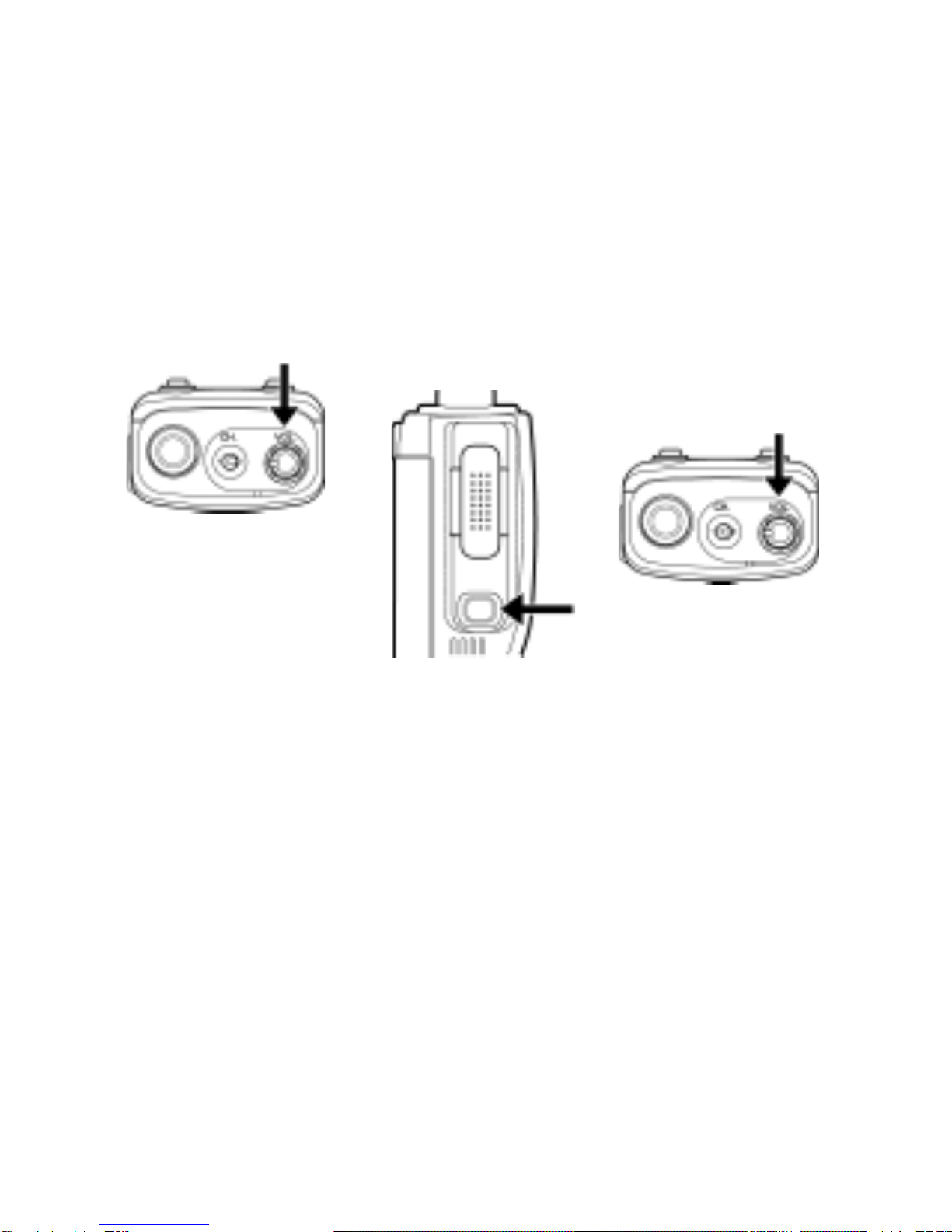
IV. Radio Control Buttons / Operation Features
A) Push-To-Talk (P-T-T) button (left side of radio) Press and
hold while speaking into the radio microphone, release to
listen to incoming messages
B) Monitor button (left side of radio) Press and hold to turn
radio squelch off. Release to turn squelch back on.
C) Microphone (front of radio)
D) Speaker (front of radio)
E) Channel switch (top panel of radio)
F) LED Indicator (top panel of radio) Identifies transmit
(red), receive (signal only) orange, (signal + CTCSS) green,
setup mode (orange), battery low (flashing red)
G) Power / volume control (top panel of radio) Powers radio
on and adjusts radio volume
H) Speaker microphone jack (right side of radio)
A
B
C
D
FG
E
H
10
V. Radio Operation
Power On / Transmit
Power on the radio by turning the power / volume
control clockwise out of detent. You will hear a
confirmation tone on power-up. To adjust radio
volume, press and hold the monitor button then
rotate the control further clockwise.
Use the channel switch to choose the desired channel.
To transmit, place the radio microphone approximately
2” (5 cm) from your mouth then press and hold the
P-T-T bar while speaking in a normal tone. Release
the P-T-T bar when you are finished speaking; the radio
will be placed into receive mode.
If the battery pack voltage becomes too low for operation
to continue, transmission will stop and the top-panel
LED will blink red. Change or charge your battery to
continue radio operation. Refer to “Low Battery Warning”
on page 19.

11
V. Radio Operation, continued
NOTE: The channel in use may have been programmed
with a signaling code. Refer to “CTCSS Tone Signaling”
on page 13.
Channels are pre-programmed with frequencies and
CTCSS tones. Refer to “Factory Default Channel Settings”
on page 18.
VI. Channel Frequency Selection
NOTE: Read all steps before attempting this process,
as the radio will exit the setup mode if keypresses are
not performed within 5 seconds.
Change the channel frequency by using these steps:
1. Press and hold the P-T-T bar and monitor bar simul-
taneously, then turn the power ON. Continue
to press both bars until the top-panel LED lights
orange. Release the P-T-T and monitor bars.
2. Press the P-T-T bar again. The LED now changes
from orange to red, and a beep sounds. The radio
is now in frequency setup mode.
3. Use the channel switch to choose the channel you
want to set up.
4. You will press the P-T-T bar once for each frequency
selection. The P-T-T press will be accompanied
with a confirmation beep. There are a total of 5
different frequencies and 1 repeater channel for
the MURS-22 radio, defined on the next page.

12
VI. Channel Frequency Selection, continued
Action Channel Default
Beep Pattern Frequency (MHz) Default CTCSS
Press P-T-T 1 time (single beep) 151.8200 No Tone
Press P-T-T 2 times (two beeps) 151.8800 No Tone
Press P-T-T 3 times (three beeps) 151.9400 No Tone
Press P-T-T 4 times (four beeps) 01 154.5700 No Tone
Press P-T-T 5 times (five beeps) 02 154.6000 No Tone
Press P-T-T 6 times (long then Repeater
short beep) TX: 154.6000 No Tone
RX: 154.5700 No Tone
NOTE: Pressing the P-T-T bar more than 6 times will
cause an error tone to sound, and no value will be
selected.
5. Listen for the beep pattern of the selected frequency
number. This takes approximately 2 seconds.
6. Press the monitor bar to confirm the frequency
selection. The LED will show red, and blink
twice.
7. Press the monitor bar again to confirm the beep
pattern of the selected frequency number.
8. Repeat steps 3 - 7 to set up the other channel.

VI. Channel Frequency Selection, continued
Example of setting a channel to frequency no. 5: After
entering frequency setup mode, press the P-T-T bar 5
times to select frequency 5 (154.6000).
A beep sounds
with each P-T-T press.
Wait for 2 seconds to hear the
beep pattern of the frequency number.
Five short beeps
sound.
Press the monitor bar.
The LED will show red
and blink twice.
Press the monitor bar again.
Five short
beeps sound to confirm that frequency 5 has been
selected.
VII. CTCSS Tone Signaling
CTCSS Tones prevent the radio from hearing signals
unless they match coded tones in your radio. When
a received signal has a code that matches your code,
squelch will open and you will hear the signal. When
a received signal has a code different from the
one set up in your radio, squelch will not open and
you will not hear the signal.
When you transmit on a channel set up with CTCSS,
the receiving station must have a matching code in
order to hear your signal.
CTCSS Tones are selected from 38 standard signaling
codes and 11 non-standard tones. Refer to the table
at top of next page.
13

14
VII. CTCSS Tone Signaling, continued
No. Freq. No. Freq. No. Freq. No. Freq.
00 OFF 13 103.5Hz 26 162.2Hz 39 69.3Hz
01 67.0Hz 14 107.2 27 167.9 40 159.8
02 71.9 15 110.9 28 173.8 41 171.3
03 74.4 16 114.8 29 179.9 42 177.3
04 77.0 17 118.8 30 186.2 43 183.5
05 79.7 18 123.0 31 192.8 44 189.9
06 82.5 19 127.3 32 203.5 45 196.6
07 85.4 20 131.8 33 210.7 46 199.5
08 88.5 21 136.5 34 218.1 47 206.5
09 91.5 22 141.3 35 225.7 48 229.1
10 94.8 23 146.2 36 233.6 49 254.1
11 97.4 24 151.4 37 241.8
12 100.0 25 156.7 38 250.3
NOTE: Selecting “00” will turn signaling OFF.
VIII. CTCSS Tone Setup
Refer to the codes listed above, and remember:
1. When selecting a single digit number (0 - 9),
always use 2 digits (00 - 09).
2. When you are confirming the selected signaling
number, there will be a short pause between
the 10’s digit and the 1’s digit.
Other manuals for MURS-22
1
Table of contents
Other TruTalk Two-way Radio manuals


Popular Two-way Radio manuals by other brands

Headline
Headline HL-1000 owner's manual

Motorola
Motorola VL50 user guide

switel
switel WTC590 operating instructions

Silicon Laboratories
Silicon Laboratories EZRadio-2WayLink-DK user guide

Motorola
Motorola RDU2080d - RDX Series On-Site UHF 2 Watt 8 Channel Two Way Business... user guide

Wintec
Wintec LP-4604+ user manual


