TSA model Infusion 700E User manual

Welcome to the TSA family and
congratulations on your new purchase.
Please read this instruction manual carefully
to ensure you understand every step of the
build process. Most of all happy building
and we look forward to seeing you around
the world at many events.
Contents
1~2. Introduction
3. Safety instructions prior to assembly
4. Tools required for assembly
5~26. Parts assembly
27. Blade tracking adjustment
28~29. Operation mode
30. Flying notes
31~36. Parts package list
www.tsamodel.com

1
1: Beginners should obtain safety and technical guidance from an experienced individual, since learning alone to
operate this machine is potentially dangerous.
2: Choose a safe flying area that is free of obstruction and people.
3: Do not fly in a potentially dangerous environment.
4: Do not operate while standing on tilted ground to avoid loss of balance.
5: Do not operate in an awkward body posture. Do not insert hands and objects in rotating parts.
6: Keep a safe distance from the unit and be sure to operate the unit within the limits of your ability. Failure to operate
this unit properly may result in serious harm such as physical injury, damages to property, and even death.
7: Enjoy flying while observing safety rules and regulations. Fatigue brought upon by continuous operation may result
in impaired judgment that may lead to accidents.
8: Inquiries regarding repairs and services should only be made to TSA authorized dealers or TSA technical support
department. Individual lacking proper training or knowledge necessary for repair may not only impair the unit's
performance,but also increases the risk of accidents or injury. The engine must be turned off before performing any
repairs or adjustments. Repair damaged parts before storage using only TSA manufactured parts. When storing or
transporting the units, secure the unit carefully to avoid fuel loss, damage, or injury.
1: Check that tools used for assembly and maintenance has been put away.
2: Check that there are no loose screws and parts.
3: Check that the rotor blades are not damaged or cracked, especially in the vicinity of the blade holder.
4: Check that electronic equipment and servos operates smoothly.
5: Check that the position of the transmitter's throttle stick and engine carburetor are at their lowest positions.
6: Check that the receiver receives signals properly.
7: Check and ensure that all necessary parts are sufficiently lubricated.
8: Do not use it in other electric equipments and magnetism place, or they will influence each other.
1: When starting the engine, be sure to hold the rotor head firmly so the rotor head does not rotate.
2: When taking off, the unit should be positioned at least 15 meters away from the operator. Be sure to check for people
and dangerous object in the surrounding area before takeoff.
3: Adjust the tracking right before takeoff. Do not come near more than 5 meters when doing so.
4: Land the unit immediately if abnormal noise or vibration is observed. Then stop the engine and perform complete
check for cause of problem.
5: Be responsible when operating this unit, as reckless or improper behavior may cause accidents or injury to self or
others. Observe all safety rules and regulation while enjoy operating this unit safely and responsibly.
While in flight
In-flight safety inspection
Pre-flight inspection
Using battery matters
1: New battery must be charged before use.
2: Battery should not be overcharged . If the battery is heat, stop charging, and take it out immediately..
3: The charge voltage for one cell should not be over 4.20V, and the all 6S battery should not be over 25.2V.Please
use reliable and precision charger.
4: It's better not to use the battery over 70% of its voltage, or better to stop flying when the battery is less than 21.6V.
This is to keep the performance of the battery,ensure the capacity and charge-discharge cycles.
5: It's battery to keep 3.6V to 3.9V voltage in the battery when store for a long time.
6: For 3D flying, the flying time should not be over 5 minutes.
7: If you are not confidence in charge, please contact with the local distributor.
2
1: Immediately inspect parts after every flight. Be sure to replace, retighten any missing or loose screws and replace
any damaged parts.
2. Wipe down grease, oil, dirt and dust with a clean cloth.
3: If not fly in long time, please take out the connector between the end of battery and the end of motor.
4: Store the unit in an area free of direct sunlight, or other areas that may result in rise in temperature (e.g., car).
Instead, store in a shaded and ventilated area, and keep out of reach of children.
After-flight safety inspection
1: To reduce the risk of accidents and injuries, do not use parts other than those found in this manual or TSA catalog.
TSA will not be responsible for problems caused by using non-genuine TSA parts.
2: If the rotor blades should strike the ground during flight, there may be tiny cracks or loosening in various places
even though damages may not be clearly visible to naked eyes. If damage to the rotor blade is not fixed before
flight, cracks and loosening may increase during flight that would lead to severe consequences. The rotor head
may disassemble from the blade holder, which spins at a speed of 1200/2000 rpm, and may fly off from the blade
holder. If in doubt regarding the condition of any part, replace the part immediately using only genuine TSA parts.
3: TSA will not be held responsible for damages or crash as a result from any loose screws and/or improper
maintenance.
4: Radio wave transmitting distance is approximately one kilometer or more, therefore operator must check no other
operators in the surrounding vicinity are using the same radio frequency.
5: This remote control model is not a toy, rather a precise machine. Proper assembly and adjustments must be made
in order to avoid the risk of injuries or accidents. Operator should operate this unit safely and properly. Failure to
operate this unit properly may result in serious harm such as physical injury, damages to properties, and even death.
The operator is responsible for all damages, because TSA cannot control how the unit was assembled and used.
6: Recommended 14 years .
Caution
Warning
Please abide by regulations in your country while enjoying
the pleasure brought to you by the series.
TSA 700E
+
1. Before assembly, read the instruction manual thoroughly and familiarize yourself with the unit's structure
and assembly procedures. Failure to assemble the unit properly may not only impair performance but also
increases the risk of danger.
2. Before assembly, check description and quantity of parts. In the event of missing or defective items, contact
retailer of original purchase where authorized distributor or TSA support department can be located.
3. Apply lubricant and retainers on locations as indicated .
4. In the instruction manual, refer to the left hand column to check the type and quantity of parts.
3
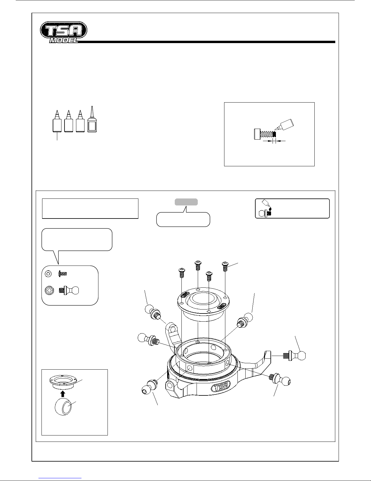
Glue width :1.5mm
Lock
Preassembly precautions
Diagram for applying thread lock
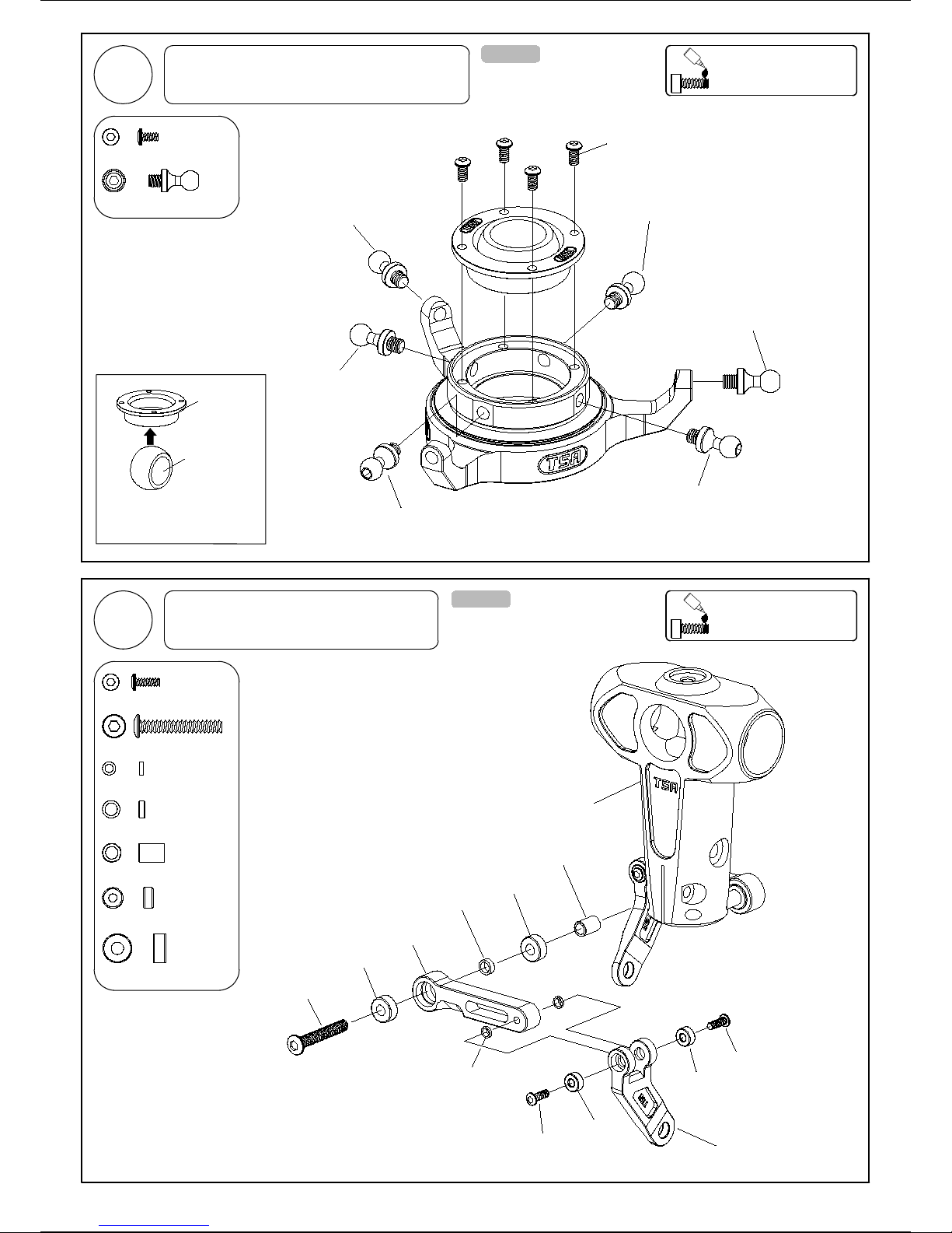
Swashplate Assembly
Parts order number
Part name and quantity in
this diagram is to 1:1 ratio
T-016-07
Lock
Please apply loctite when
locking all metal screws .
Insert pivot ball in the above illustrated
orientation. The ball will clip in and
centralise easily.
Coupling
Pivot ball
(Ø12)
Assembly Tip
M2-4 Bind Screw 4
12mm Ball 6
12mm Ball
M2-4
Bind Screw
Lock
SG
CA=Cynoacrylate adhesive
CA
AB
Self-furnished
12mm Ball 12mm Ball
12mm Ball
12mm Ball
AB=5 minute expoxy / A=3 : B=1
Lock=Thread lock
SG=Silicone grease
4
1
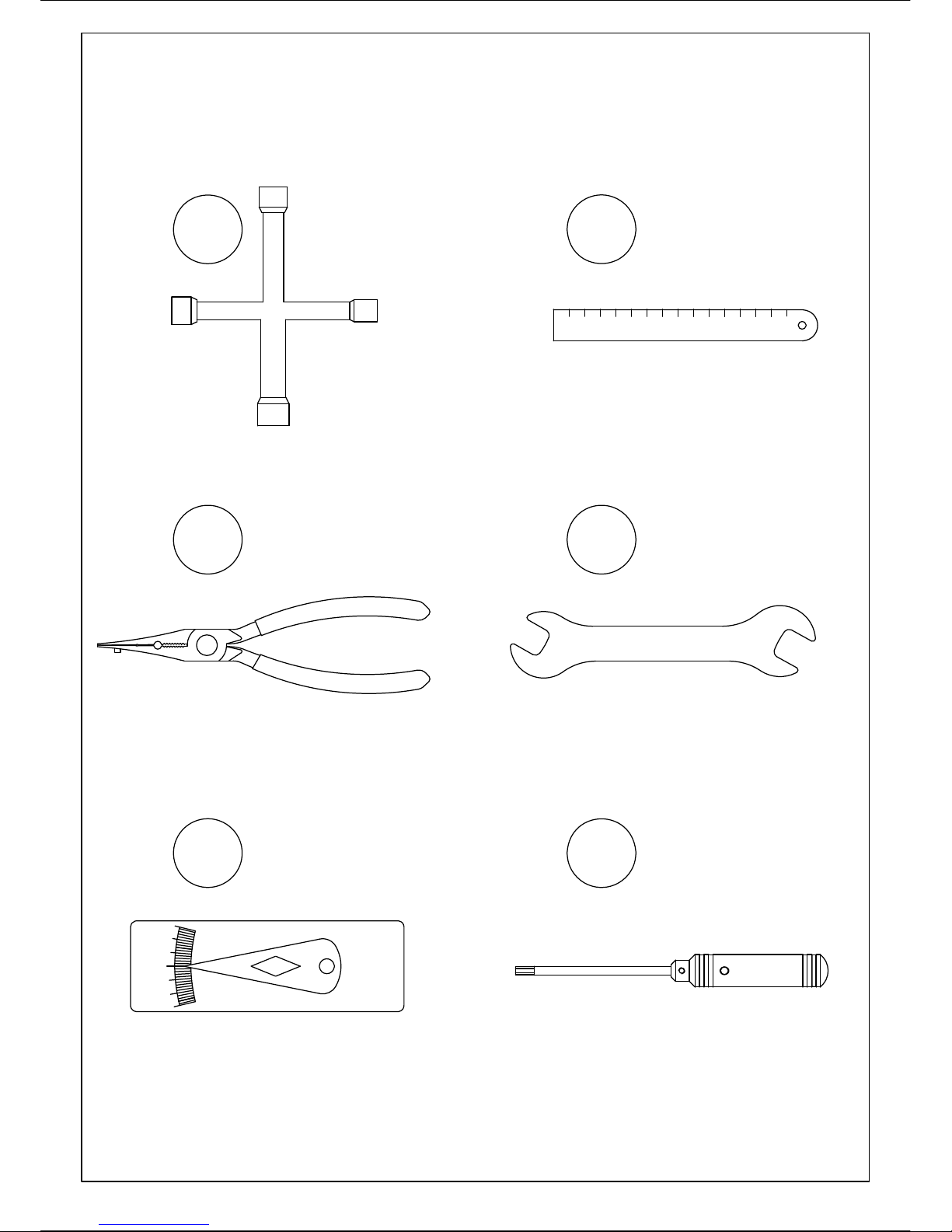
TOOLS REQUIRED FOR ASSEMBLY
Universal ball link plier
Metric ruler
(Over 30cm)
8
75.5
Cross wrench
(5.5~12)
Spanner
(6mm/8mm/12mm/21mm)
(Allen head) Screw drivers
(1.5mm/2mm/2.5mm/3mm/3.5mm/
4mm/5mm)
0
-5
-10
-15
+5
+10
+15
Pitch gauge
3 4
56
2
12

5
1Main Frame Assembly-1 T-005-01
T-007-05
30.5mm
Canopy front support
Custom Washer
M3-8
Cap screw
37.5mm
Canopy rear support
Main shaft bearing block
Ø5xØ10x4
Flange Brg
M3-6
Bind screw
Right frame
T-001-21
Equipment required for assembly
Transmitter( 7 channels ) Rudder servo
Servos Charger
3 Axis gyro system
4.8 V
1800 mA
Receiver battery
Receiver
On/off switch
+
4500~11000W /
500~550KV
Brushless motor x1
SBH-120A Brushless ESC x1 6S LiPo 4000~5000mAh x2
_
Battery +
_
+
_
ESC
Please apply loctite when
locking all metal screws .
Lock
M3-6
Cap screw
M3-6
Cap screw
2
1
3
M3-6 Bind screw
1
30.5mm Canopy front support
M3-8 Cap screw
Custom Washer 2
37.5mm Canopy rear support
Ø5xØ10x4 Flange Brg 1
2
M3-6 Cap screw
Centre main shaft bearing block
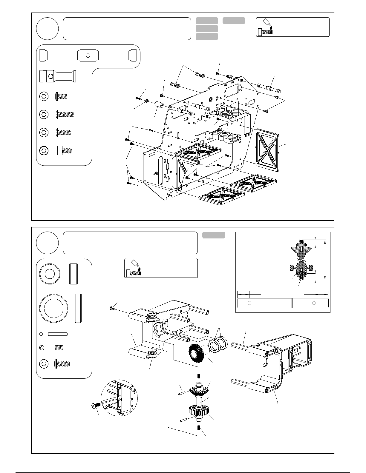
T-002-07
6
T-005-01
Ø6xØ13x5 Brg 2
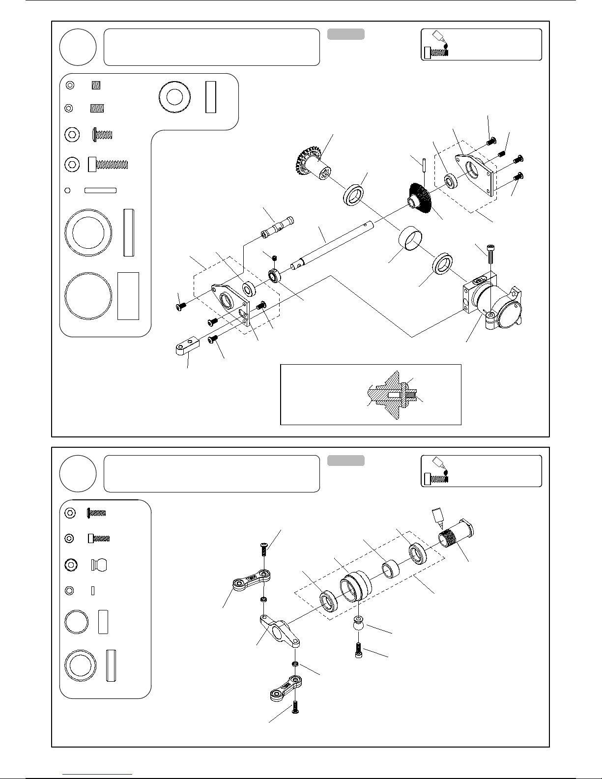
Tail Drive Gear Assembly
57mm
Tail drive gear-25T
Bevel gear
Tail drive shaft
T-019-00
Ø2x12
Locating pin Bevel gear
M3-5 SS
2
M3-5 SS
7.5mm
Centralizing the locating pin on
each gear then tightening the
M3-5 SS grub screws. Ensure
correct gear orientation.
M3-5 SS
Locating pin
Locating pin Ø2x12 2
Plastic tail boom clamp
Hex insert
9mm
Ø12xØ18x4 Brg
Ø6xØ13x5 Brg
Plastic tail boom clamp
Ø12xØ18x4 Brg 2
M3-8
Bind screw
1
M3-8 Bind screw
Insert M3-8 into boom clamp only a few
turns as this will be tightened once boom
is installed.
M3-8
Bind screw
7.5mm 9mm
T-009-02
T-022-02
Please apply loctite when
locking all metal screws .
Lock
Please apply loctite when
locking all metal screws .
Lock
2Main Frame Assembly-2
3
M3-10
Bind screw
M3-8
PH screw
M3-8
PH screw
M3-8
PH screw
M3-6
Cap screw
M3-8
PH screw
Canopy damper
Flange washer
Rigidity brace
M3-6
Bind screw
M3-6
Bind screw
61mm
Cross member
23mm
Servo support
23mm Servo support 2
61mm Cross member 3
2
M3-6 Bind screw
M3-8 PH screw 10
M3-10 Bind screw 1
M3-6 Cap screw 2
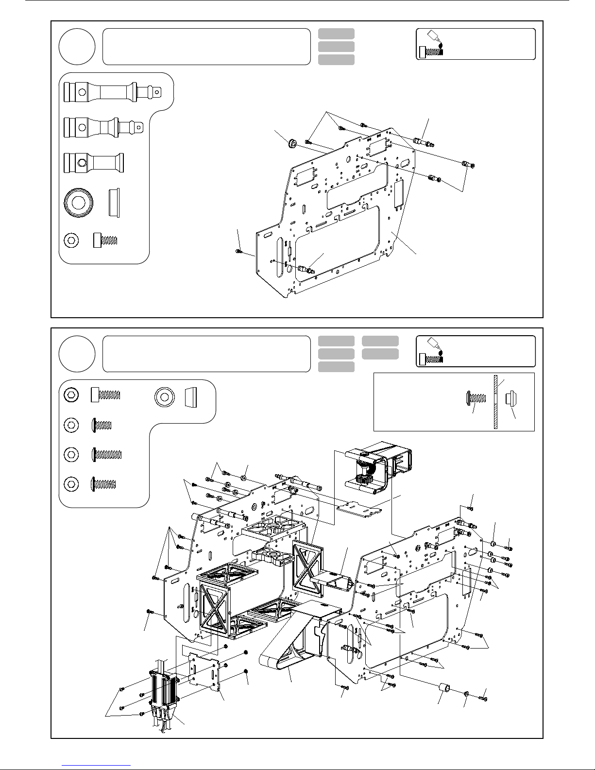
7
T-002-07
T-005-01
10
M3-6 Bind screw
M3-8 Cap screw 8
Custom washer 8
T-009-02
T-004-00 T-019-00
1
M3-10 Bind screw
T-005-01
T-022-02
Ø5xØ10x4
Flange Brg
37.5mm
Canopy rear support
23mm
Servo support
M3-8 PH screw 20
30.5mm
Canopy front support
Left frame
T-001-20
M3-8
Cap screw Custom Washer
M3-8
PH screw
M3-6
Bind screw
M3-6
Bind screw
M3-6
Bind screw
Gyro mount
M3-8
Cap screw
Canopy damper Flange washer
Custom Washer
Battery mount
M3-10
Bind screw
M3-8
PH screw
M3-8
PH screw
M3-8
PH screw
M3-8
PH screw
M3-8
PH screw
M3-8
PH screw
M3-8
PH screw
M3-8
PH screw
Gyro plate
Place nut insert into the backside
of the mainframe. Tighten screw
until nut insert is seated. Lastly,
remove screw.
M3-6
Bind screw Nut insert
ESC plate
M3-8
PH screw
M3-6
Bind screw
4Main Frame Assembly-3 Please apply loctite when
locking all metal screws .
Lock
5Main Frame Assembly-4 Please apply loctite when
locking all metal screws .
Lock
1
1
30.5mm Canopy front support
37.5mm Canopy rear support
Ø5xØ10x4 Flange Brg 1
23mm Servo support 2
4
M3-6 Cap screw
M3-6
Cap screw
M3-6
Cap screw
M3-6
Bind screw ESC
ESC plate
Nut insert

8
T-002-07
T-012-00
T-013-01
M3-18 Cap screw
4
M3 Nylon nut
M4-4 SS 4
4
Ø3xØ8x0.8 Washer 4
Landing skid tube
Landing skid
M4-4 SS
Landing skid cap
Landing skid cap
M3 Nylon nut
M3-18
Cap screw
Plastic Skid Mount
Ø3xØ8x0.8
Washer
M3-12
PH screw
M3-12
PH screw
M3-12
PH screw
M3-12
PH screw
8M3-12 PH screw
T-007-05
M4-4 SS 1
M4-12 Cap screw 4
6
M3-8 Cap screw
Custom Washer 6
Grommet * 8
M3-8
Cap screw
T-012-00
T-030-04
Custom Washer
M3-8
Cap screw
M3-6
Bind screw
3
M3-6 Bind screw
Custom Washer
T-008-01
CA
CA
12T : 126T = 1 : 10.5
13T : 126T = 1 : 9.69
11T : 126T = 1 : 11.45
14T : 126T = 1 : 9 Not included
Standard
Gear ratio
T-030-06
Please apply loctite when
locking all metal screws .
Lock
6Landing Gear Assembly-1
7Landing Gear Assembly-1
M4-4 SS
M4-12
Cap Screw
Spur gear
Brushless
motor
Motor mount
T-011-11
M3-6
Bind screw
9
Please apply loctite when
locking all metal screws .
Lock
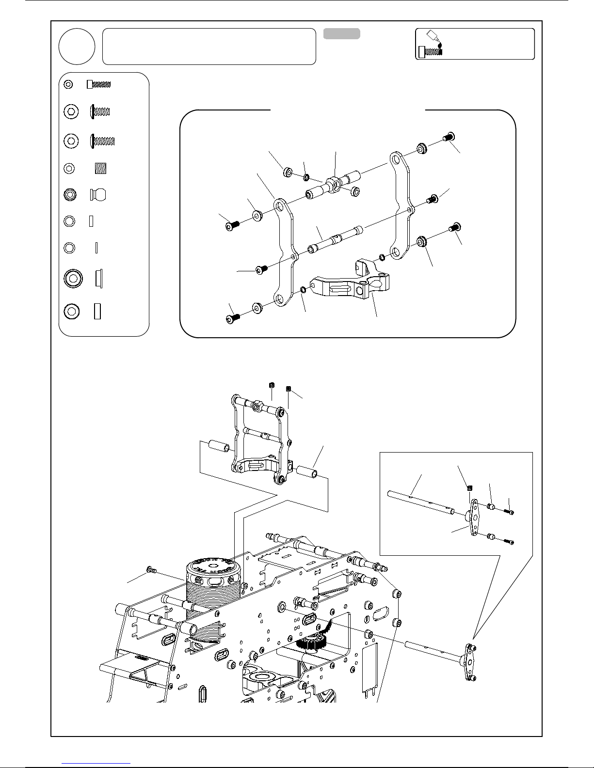
8Elevator Lever Assembly
M4-4 SS
Spacer
Ø5xØ7x16.55
5.7mm Ball
Elevator lever
M2-7
Cap Screw
M4-4 SS
Elevator shaft
M3-6
Bind screw
Anti-Rotation Elevator Lever (ARE)
Ø3xØ6x2.5
Flange Brg
Ø3xØ6x2.5
Flange Brg
M3-8
Bind screw
M3-8
Bind screw
M3-8
Bind screw
M3-8
Bind screw
M3-6
Bind screw
M3-6
Bind screw
50.5mm
Cross member
Ø3xØ6x2.5 Brg Spacer
Ø3xØ4.2x1.25
ARE supports
ARE pivot arm
Spacer
Ø3xØ4.2x0.5
ARE pivot block
Ø3xØ6x2.5 Brg 2
4
Ø3xØ6x2.5 Flange Brg
2
5.7mm Ball
M3-6 Bind screw 3
M2-7 Cap screw 2
Spacer Ø3xØ4.2x0.5 2
M4-4 SS 3
M3-8 Bind screw 4
Spacer Ø3xØ4.2x1.25 1

M2.6-18
PH screw
10
M2.6-18
PH screw
M2.6-18
PH screw
M2.6-26
PH screw
1.5mm
Servo plate
Servo mounting plate
T-024-01
M2.6-18 PH screw 12
Servo mounting plate
Servo plate
Caution
Note the orientation of the servos
as both the elevator and throttle
servo are mounted inside the main
frames
Servo plate
Servo plate
For extending the rudder servo cable.
Servo extension cable-120mm (Not included)
M2.6-26 PH screw 4
Screw included
with the switch
On/off switch
Switch plate
Servo plate
Servo spacer
Servo mounting plate
Aileron / Pitch
Rudder
Elevator
Pitch / Aileron
Wire clamp
Wire clamp * 3
9Servo Assembly
Caution
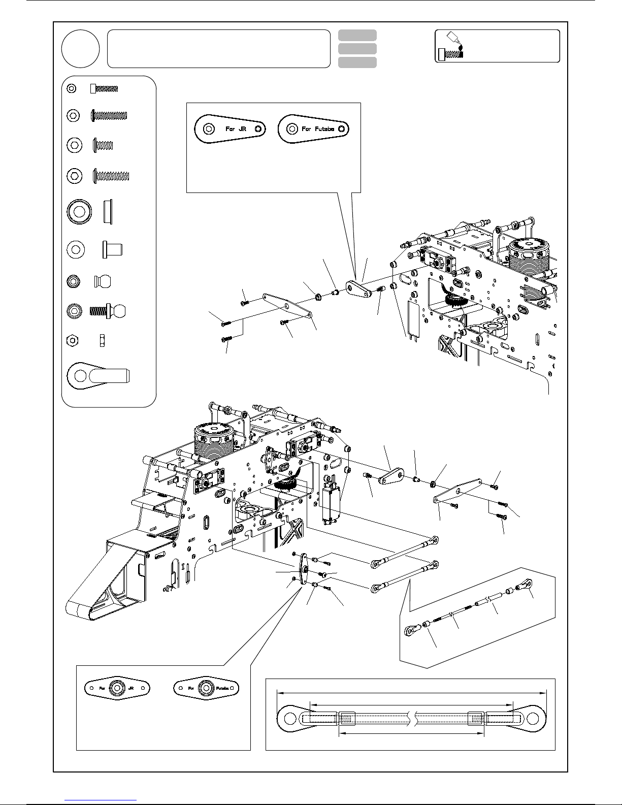
11
Servo support plate
Futaba
JR
M3-12
Bind screw
M2.6-12
Bind screw
Servo support guide
Ø3xØ6x7
Ø4xØ7x2.5
Flange Brg
Lever
T-025-00
Both JR and Futaba servo horns are provided. Please use the
appropriate set for your application.
13mm Ball
JR x 2 Sets Futaba x 2 Sets
T-022-02
Ø4xØ7x2.5 Flange Brg
M2.6-12 Bind screw
2
2
2
Servo support guide Ø3xØ6x7
4
M3-6 Bind screw
Ball link-long (23mm) 4
2M2 Nut
2
5.7mm Ball
M2-8 Cap screw 2
13mm Ball 2
JR x 1 Set Futaba x 1 Set
Both JR and Futaba servo horns are provided. Please use the
appropriate set for your application.
Lever
M2-8
Cap screw
5.7mm Ball
M2 Nut
Screw attached
13mm Ball
Lever Servo support guide
Ø3xØ6x7
Ø4xØ7x2.5
Flange Brg
M3-12
Bind screw
JR
Futaba
Servo support plate
M2.6-12
Bind screw
T-020-03
2
M3-12 Bind screw
10 Servo Support Assembly Please apply loctite when
locking all metal screws .
Lock
M2.2*100L
Carbon fiber shaft
Carbon fiber tube
(79.5mm)
Ball link-long
(23mm)
About 81mm
100mm
About 126mm
M3-6
Bind screw
M3-6
Bind screw
M3-6
Bind screw

12
1
M4-27-6 Cap screw
Plastic main gear (126T)
M3-8 Bind screw
Ø15xØ21x4 Brg
Ø15xØ21x4 Brg
Ø15xØ23x11
One way bearing
Auto-rotation drive shaft
Plastic tail drive gear (113T)
Auto-rotation case
Pre-assembled
Loosen lower bearing block bolts. Insert main gear assembly and main
shaft. While pressing up on the bearing block tighten the 4 lower bearing
block bolts. Ensure no up/down free play by pulling on the main shaft.
Caution
Caution
6mm
27mm
Only use long shank M4
mounting screw!
M4
Nylon nut
M4-27-6
Cap screw
T-007-05
Ø15xØ21x4 Brg 2
Ø15xØ23x11 One way bearing 1
M4 Nylon nut
M3-8 Bind screw
1
6
Main shaft free play adjustment
Auto-rotation mount
One way bearing collar
M2-6 Cap screw
M2-6 Cap screw 8
Spacer
Ø4xØ5.5x3.25
Spacer Ø4xØ5.5x3.25 2
12.4mm
4.5mm
Main shaft
Please note the direction
of bearing .
M2-4
Bind screw
Insert M2-4 retaining blind
screws after installing the
bearing
M3-6
Bind screw
M3-6
Bind screw
M3-6 Bind screw 4
M2-4 Bind Screw 2
T-015-09
SN
S pole faces up N pole faces up
( Not included )
CA
M2-6
Cap screw
M2 Nut
Goy sensor
(Not included)
Top view
M2 Nut 2
1.5mm
Wire clamp * 1
Magnet
11 Main Gear Assembly Please apply loctite when
locking all metal screws .
Lock
13
Spacer Ø3xØ4.2x1.5 2
T-016-07
Ø3xØ7x3 Brg 4
M3-20 Bind screw 2
M2-6 Bind Screw
Spacer Ø3xØ4.5x6.2 2
4
Ø2xØ5x2.3 Brg 4
T-016-07
Insert pivot ball in the above illustrated
orientation. The ball will clip in and
centralise easily.
Coupling
Pivot ball(Ø12)
Spacer Ø2xØ3.2x0.9 4
Assembly Tip
M2-4 Bind Screw 4
12mm Ball 6
12mm Ball
12mm Ball
12mm Ball
12mm Ball
M2-4
Bind Screw
Mixing arm
M2-6
Bind Screw
Ø2xØ5x2.3 Brg
Ø2xØ5x2.3 Brg
Spacer
Ø2xØ3.2x0.9
Metal head block
Metal washout control arm
Ø3xØ7x3 Brg
M3-20
Bind Screw
Spacer
Ø3xØ4.2x1.5
Spacer
Ø3xØ4.5x6.2
Ø3xØ7x3 Brg
M2-6
Bind Screw
12mm Ball
12mm Ball
Please apply loctite when
locking all metal screws .
Lock
12 Swashplate Assembly
Please apply loctite when
locking all metal screws .
Lock
13 Washout Assembly
Black
Gray
40°
60°
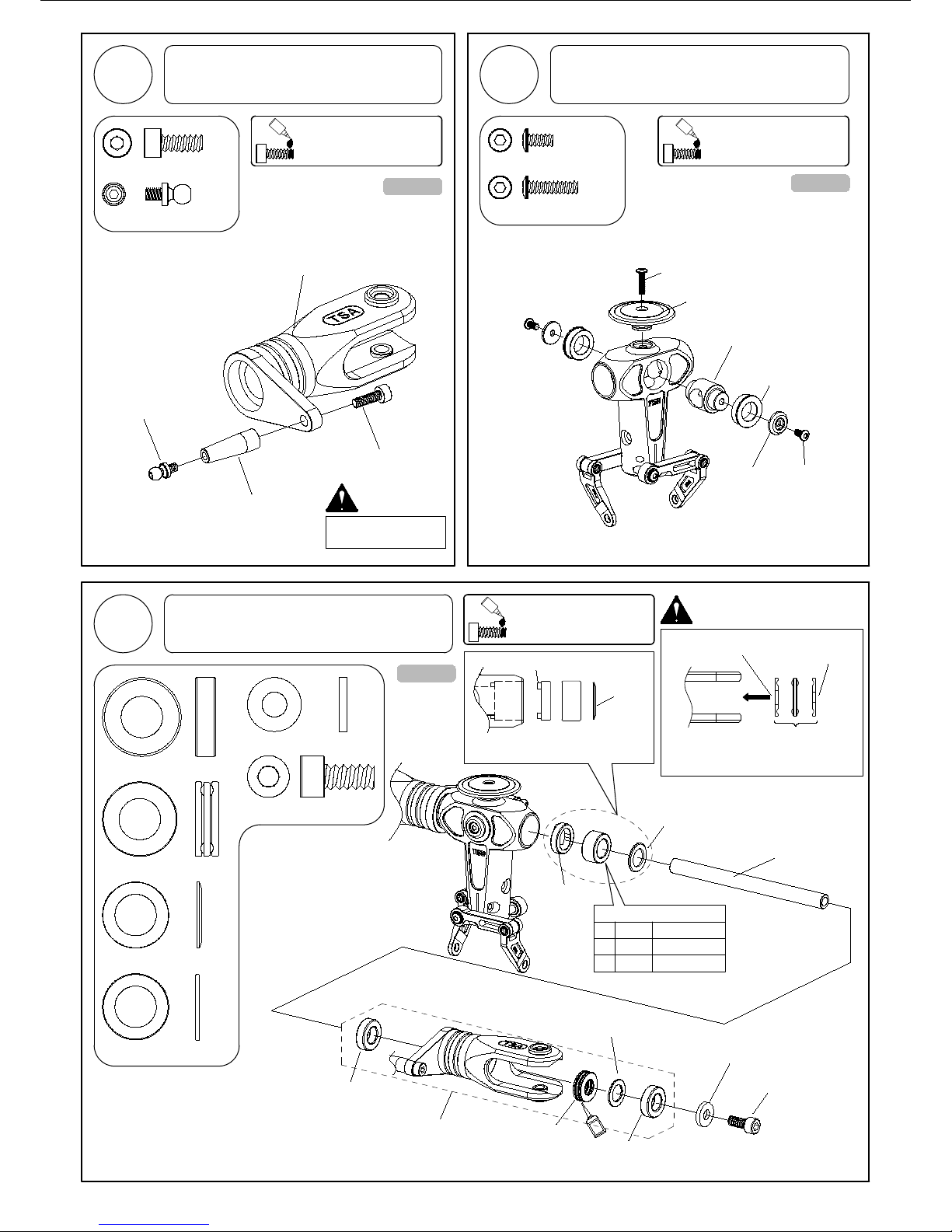
Ø10xØ18x5.5
Thrust bearing
Ø10xØ18x5.5
Thrust bearing
Ø10xØ19x5 Brg
Ø10xØ19x5 Brg 4
2
Damper
Blade grip
Larger inner diameter
(Black) Smaller inner
diameter
Spindle
Ø10xØ19x5 Brg M6-12 Cap screw
Pre-assembled
Damper shim Ø10xØ15.5x1
Shim Ø10xØ15.5x1
SG
Damper shim
Ø10xØ15.5x1
Shim
Ø10xØ15.5x1
50°
Red Not included
Standard
2
Ø10xØ18x5.5 Thrust bearing 2
M6-12 Cap screw 2
Ø6xØ13x2 Washer 2
Caution
Note direction of bearings!
Ø6xØ13x2
Washer
Feathering
shaft guides
14
M3-6 Bind screw
Caution
2
Metal blade grip
Two must be assembled
T-016-07 T-016-07
Teeter hub
M3-6
Bind screw
Custom washer
M3-12 Bind screw 1
Head button
M3-12
Bind screw
11mm Ball 2
11mm Ball
M4-10
Cap screw
Pitch arm
Acetyl bearing
T-016-07
Not included
M4-10 Cap screw 2
Note the installing direction of the feathering
shaft guides and spindle bearing spacer.
Flange Portion
Flange Portion
14 Pitch Arm Assembly
Please apply loctite when
locking all metal screws .
Lock
15 Head Block Assembly
Please apply loctite when
locking all metal screws .
Lock
16 Blade Holder Assembly Please apply loctite when
locking all metal screws .
Lock

Swashplate
M2.2*50L
M2.2*50L
T-016-07
T-020-03
15
Spacer Ø3xØ5x3.37
M3-18 SS
M3 Nylon nut
2
M3-15 Cap screw
M4-5 Bind screw 2
1
1M3-18 SS
M3 Nylon nut
Spacer Ø3xØ5x3.37 1
T-011-11
About 74mm
About 28mm
50mm
Ball link-long
(23mm)
Swashplate link orientation
Left Right
Ø3 Allen head
M4-5
Bind screw
M3-15
Cap screw
M4-5
Bind screw
M3-15
Cap screw
Adjust the position of
the Ball link, make it
touch the allen head ,
ensure the rod is in the
vertical position.
Insert the allen head into the hole as shown in the diagram ,
make sure the rocker-arm is parallel with the swashplate.
Adjust the position of ARE support,
make sure ARE support is in the
vertical position by letting its fillet
corner contact with the allen head.
Ø3 Allen head
Please apply loctite when
locking all metal screws .
Lock
17 Rotor Head Complete Assembly
Ball link-long
(23mm)
Ø3 Allen head
1
M3-3 SS
2
Ø12xØ18x4 Brg
16
M3-6 Bind screw 7
Spacer Ø17xØ18x7.95 1
M3-6
Bind screw
Ø6xØ12x4 Brg
Tail output shaft
Tail case right Metal tail gearbox clamp
Pre-assembled
Tail cross member
(29.5mm)
Ø12xØ18x4 Brg
Spacer
Ø17xØ18x7.95
Ø12xØ18x4 Brg
Bevel gear Tail case left
Pivot mount
Pre-assembled M3-3 SS
Locking collar
Ø2x12
Locating pin
Bevel gear
M3-5 SS
1
M3-5 SS
Locating pin
M3-5 SS
1M3-12 Cap screw
M3-6
Bind screw
M3-6
Bind screw
M3-12
Cap screw
Centralise the locating pin on
each gear then tighten the
M3-5SS grub screws. Ensure
correct orientation.
Ø6xØ12x4 Brg 2
Ø6xØ12x4 Brg
M3-6
Bind screw
M3-6
Bind screw
Locating pin Ø2x12 1
T-017-02
T-016-07
Tail shaft slider
Pre-assembled
Tail yoke
Ø8xØ12x3.5 Brg
M2-6
Cap screw
5.7mm Ball
Spacer
Ø8xØ9x3.5
Ø8xØ12x3.5 Brg
Lock
Metal tail pitch slider
18 Tail Gearbox Assembly-1 Please apply loctite when
locking all metal screws .
Lock
19 Tail Gearbox Assembly-2 Please apply loctite when
locking all metal screws .
Lock
M2-6
Bind Screw
Spacer
Ø2xØ3.2x0.9
M2-6
Bind Screw
Tail pitch links
5.7mm Ball
Ø8xØ12x3.5 Brg 2
M2-6 Bind Screw 2
1
1
Spacer Ø8xØ9x3.5
Spacer Ø2xØ3.2x0.9 2
M2-6 Cap screw 1

M3-18 Bind screw 1
1
5.7mm Ball
M2 Nut
Spacer
Ø3xØ5x4.5
M3-18
Bind screw
M2-8
Cap screw
Ø3xØ7x3 Brg
Tail bell crank
1
1
1M2-8 Cap screw
2
Ø3xØ7x3 Brg
M2 Nut 1
1
Spacer Ø3xØ5x4.5
5.7mm Ball
Spacer Ø3xØ4.5x3
T-018-00
2
Larger inner
diameter(Black)
Smaller inner diameter
M3-17-5 Cap screw 2
Metal tail blade grip
Fasten the tail blade to permit only slight movement .
Note the direction of the tail blade and the tail blade grip .
Note direction of bearings!
Periodically check and
perform necessary
lubrication.
T-016-07
Caution
5mm
17mm
Only use long shank M3
mounting screw!
Ø5xØ10x4 Thrust bearing 2
Ø6xØ12x4 Brg 2
Caution
17
Ø3xØ7x3 Brg
Spacer
Ø3xØ4.5x3
Ø5xØ10x4 Brg 2
Ø5xØ10x4 Brg
SG
M4 Nylon nut
Tail spindle
Ø5xØ10x4
Thrust bearing
pre-assembled
M3-17-5
Cap screw
Metal tail blade
grip
Ø6xØ12x4 Brg
M3 Nylon nut
2
M3 Nylon nut
M4 Nylon nut
Tail blade (not included)
Thickness : 4mm
20 Tail Gearbox Assembly-3 Please apply loctite when
locking all metal screws .
Lock
21 Tail Gearbox Assembly-4 Please apply loctite when
locking all metal screws .
Lock
Caution

18
Torque tube bearing location :
M2-8 Cap screw 4
M2 Nut 4
1
M3-10 Cap screw
About
140mm
Bearing carrier
Torque tube
Ø8xØ14x4 Brg
Metal tail boom clamp
Tail boom
M3-10
Cap screw
M3-5
Bind screw
Horizontal fin
M2 Nut
T/T drive end
2
Ø8xØ14x4 Brg
M3-5 Bind screw 2
Push rod guide
M2-8
Cap screw
T-026-01
T-027-02
T-028-22
M4-4 SS
Tail spindle
Tail shaft
Use the M4-4SS screw to fasten
the tail shaft and spindle. Ensure
grub screws are seated into receiver
grooves.
About 240mm
781.5mm
About 240mm
T/T drive end
Apply AB glue to shaft then slide
bearing overtop and allow to dry.
Apply oil to tail boom bearing carrier and
inside tail boom for easy T/T installation.
AB
AB
Lock
Lock
About
140mm
About
140mm
About
140mm
T-016-07
T-017-02
Assembly Tip
M4-4 SS
Add grease
Add grease
22 Tail Gearbox Assembly-5 Please apply loctite when
locking all metal screws .
Lock
Please apply loctite when
locking all metal screws .
Lock
Caution
23 Tail Gearbox Assembly-6
M2-6
Bind Screw
Spacer
Ø2xØ3.2x0.9
1
M4-4 SS
2
M2-6 Bind Screw
Spacer Ø2xØ3.2x0.9 2
Other manuals for Infusion 700E
2
Table of contents
Other TSA model Toy manuals

TSA model
TSA model infusion 600N PRO User manual

TSA model
TSA model INFUSION 700N User manual

TSA model
TSA model Infusion 700E User manual

TSA model
TSA model Infusion 600E Pro User manual

TSA model
TSA model Infusion 600E Pro User manual

TSA model
TSA model infusion 7000n User manual

TSA model
TSA model INFUSION 700N User manual

TSA model
TSA model Infusion 600n Platinum User manual

TSA model
TSA model Infusion 700E User manual


