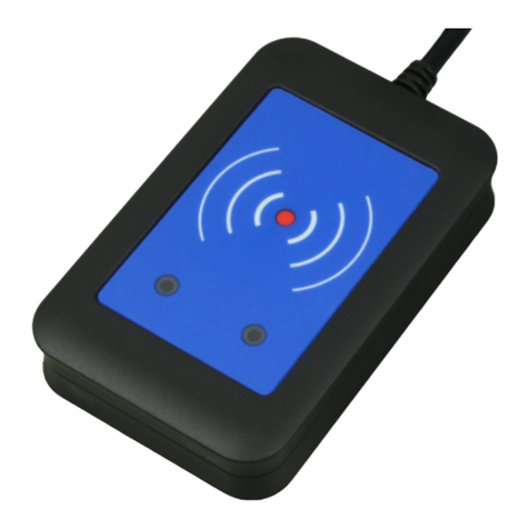
TSS DUR 120 USB User manual

1
DUR 120 USB
and
DUR 120 ETHERNET
Desktop UHF RFID reader
User Guide
Ver. 1.3
04/2016
TSS COMPANY s.r.o., Pod Rovnicami 41, 84104 Bratislava, Slovakia

2
© Copyright 2015, TSS COMPANY, s.r.o.
No part of this manua may be reproduced in any form or by any means, e ectronic,
mechanica , recording, or otherwise, without the prior written permission of TSS COMPANY.
TSS COMPANY reserves the right to modify its product specifications without any further
notice. For up to date information p ease visit www.tsscompany.eu.
The information contained herein has been carefu y checked and is be ieved to be accurate.
However, TSS assumes no responsibi ity for inaccuracies.

3
Contents
1
Introduction ........................................................................................................................ 4
2
Connecting the reader and installing the USB driver ......................................................... 4
3
Ethernet connection (Only DUR 120 ETHERNET) ............................................................... 4
4
Functionality test ................................................................................................................ 4
5
Technical specifications ...................................................................................................... 5
6
TSSTagger ........................................................................................................................... 7
Installation ................................................................................................................... 7
Inventory Tab ............................................................................................................... 8
Read/Write Tab ......................................................................................................... 10
Kill/Lock Tab ............................................................................................................... 12
EPC Tab ...................................................................................................................... 14
Settings Tab ............................................................................................................... 16
Reader Settings .................................................................................................. 17
Inventory ............................................................................................................ 17
Connect Tab ............................................................................................................... 18
Connection Type (a) ........................................................................................... 19
Serial Port Settings (c) ........................................................................................ 19
LAN Settings (f) ................................................................................................... 19
Device Search (j) ................................................................................................. 20
Device Net ork Settings (q) ............................................................................... 21
7
TSSUpdater ....................................................................................................................... 22
Installation ................................................................................................................. 22
Firm are update ....................................................................................................... 22
Troubleshooting......................................................................................................... 26
8
References ........................................................................................................................ 27
9
Revision History ................................................................................................................ 28
Annex 1: Declaration of Conformity......................................................................................... 29

4
1Introduction
The desktop UHF RFID reader DUR 120 a ows so ution deve opers to use app ications that
require desktop reading and writing of EPCg oba UHF C ass 1 Gen 2 tags. The DUR 120 reader
is contro ed by and powered from a host PC or aptop through a USB interface. In case of DUR
120 ETHERNET the ethernet interface can be used for communication purpose.
2Connecting the reader and installing the USB driver
The DUR 120 reader can be connected to a PC or a notebook via a USB interface. When
connecting the device for the first time, the user has to insta the necessary device drivers to
a ow Windows to recognize the reader. The reader emu ates a virtua seria port.
You can down oad VCP drivers for Windows based systems from this website:
http://www.ftdichip.com/Drivers/VCP.htm
You can down oad detai ed driver insta ation guide from this website:
http://www.ftdichip.com/Support/Documents/InstallGuides.htm
3Ethernet connection (Only DUR 120 E HERNE )
A standard ethernet connection with an 8-pin RJ connector using 2 twisted pairs has to
be used to connect DUR 120 ETHERNET. The DUR 120 ETHERNET se ects automatica y
between the USB and ethernet interface based on the first received va id packet after the start
up from USB or ethernet interface. The DUR 120 ETHERNET reader is powered through the
USB connector.
4Functionality test
The user can easi y test the basic functiona ities of the reader with the TSSTagger demo
software. Chapter 6 of this guide contains more information on TSSTagger.

5
5echnical specifications
DUR 120 USB:
Frequency Band: 865 ÷ 868 MHz (ETSI EN 302 208 v. 1.4.1.)
Number Of Channels: 4 (comp iant to ETSI EN 302 208 v. 1.4.1.)
RF Po er Output – e.r.p.: max. 14 dBm
Modulation: DSB-ASK
Antenna Gain: 5 dBic
Antenna Polarization: Integrated circu ar po arized antenna
Air Interface Protocol: EPCg oba UHF C ass 1 Gen 2 Version 2.0.0
Supports tag vendor specific custom commands
Supports NXP UCODE DNA
Tag Communication Rate: 40 kbps
Data Encoding
Interrogator -> Tag:
PIE, 40kHz
Data Encoding
Tag -> Interrogator:
FM0, 40kHz
Tag Read Rate: Up to 50 tags/second
Tag Read Range: Up to 50 cm, depending on tag and environment
(Tested with an ALN-9662 tag)
USB Interface:
USB 2.0 Fu Speed
It appears as USB seria port
USB mini-B connector
User Interface:
Power LED (orange)
Status LED (green)
Operating Temperature: -20 °C do +55 °C
Po er Supply: 5 VDC (Powered by USB interface)
Po er Consumption: max. 200mA
Dimensions: 110mm L x 110mm W x 38mm H
Weight: 240 g
Length Of USB Cable: 1,8m

6
DUR 120 ETHERNET:
Frequency Band: 865 ÷ 868 MHz (ETSI EN 302 208 v. 1.4.1.)
Number Of Channels: 4 (comp iant to ETSI EN 302 208 v. 1.4.1.)
RF Po er Output – e.r.p.: max. 14 dBm
Modulation: DSB-ASK
Antenna Gain: 5 dBic
Antenna Polarization: Integrated circu ar po arized antenna
Air Interface Protocol: EPCg oba UHF C ass 1 Gen 2 Version 2.0.0
Supports tag vendor specific custom commands
Supports NXP UCODE DNA
Tag Communication Rate: 40 kbps
Data Encoding
Interrogator -> Tag:
PIE, 40kHz
Data Encoding
Tag -> Interrogator:
FM0, 40kHz
Tag Read Rate: Up to 50 tags/second
Tag Read Range: Up to 50 cm, depending on tag and environment
(Tested with an ALN-9662 tag)
Ethernet Interface : 10/100 Mbps
TCP/IP protoco s
Supports IP Configuration
- Static, DHCP
Supports DNS
(Defau t configuration is: Static IP Address,
192.168.0.110)
USB Interface:
USB 2.0 Fu Speed
It appears as USB seria port
USB mini-B connector
User Interface:
Power LED (orange)
Status LED (green)
Operating Temperature: -20 °C do +55 °C
Po er Supply: 5 VDC (Powered by USB interface)
Po er Consumption: max. 450 mA
Dimensions: 110mm L x 110mm W x 66mm H
Weight: 290 g
Length Of USB Cable:: 1,8m

7
6TSSTagger
The user interface of TSSTagger is split into five sections, or tabs:
Inventory Tab:
This is the main tab of the application used to connect and disconnect the reader and to
start and stop the HID emulation. This tab also contains the inventory list here EPC
numbers are stored.
Read/Write Tab:
This tab is used to read from and rite to different memory banks of the tag.
Kill/Lock Tab:
This tab is used to adjust lock actions and permissions for different memory banks and
pass ords.
EPC Tab:
This is the application’s EPC editor designed for easy EPC number editing.
Settings Tab:
This tab contains several application settings.
Installation
-Extract the contents of TSSTagger.zip into the program directory.
-Double-click vcredist_x86.exe to start the setup of Microsoft Visual C++ 2013 x86
Redistributable soft are package.
-The setup program guides you through the installation.
-Wait until Microsoft Visual C++ 2013 x86 Redistributable soft are package has been
successfully installed.

8
Inventory Tab
a. Connect reader:
This button serves to connect and disconnect the reader. To ensure the reader
ill connect properly, the user should ait until Windo s USB drivers have
properly installed (this can be confirmed in the lo er right corner of the screen in
the Windo s task bar notification area).

9
b. Clear inventory list:
This button c ears the inventory ist.
c. Inventory list:
This is where read counts of tags and EPC numbers are isted, sorted by time
stamp. The maximum number of tags to be disp ayed in the inventory ist can be
set in the “Settings Tab”. The ist can be c eared using the “Clear inventory list”
button ocated under the inventory ist.
d. Read Single-Tag:
This button a ows the user to read the EPC number of the tag, disp aying it in the
inventory ist.
e. Read Multi-Tag:
This button a ows the user to read the EPC numbers of mu tip e tags.
f. Main log:
The main og shows the connection status, sent and received packets and error
messages re ated to seria port communication. Content of the main og can be
copied and pasted or c eared using the right-c ick context menu.
g. Status Bar:
The status bar shows information about the current y connected device and any
other messages.

10
Read/Write Tab
a. Tag selection:
These radio buttons allo the user to select bet een orking ith the first tag
responding to the reader and the tag specified by the EPC number.

11
b. Memory Bank Selection:
Read and Write operations take p ace in one of the four memory banks
(RESERVED, EPC, TID, USER). This combo box se ects the memory bank to be used.
c. Read Section:
This section is used to read data from one of the four memory banks of the tag.
The read operation is specified by an address (a decima number representing the
word starting address) and ength (a decima number representing the word
count to be read). After the “Read” button is c icked and the process is successfu ,
the requested data is disp ayed in the Read Data fie d in hexadecima format. If
the process fai s, the Read Status shows an error message. If the memory bank to
be read from is password protected, it is necessary to check the Use Access
password checkbox and enter the password into the access password fie d.
d. Write Section:
This section is used to write data from one of the four memory banks of the tag.
The write operation is specified by an address (a decima number representing
the word starting address). After the “Write” button is c icked, data from the
Write data fie d is send to the reader. The success of the operation is indicated in
the Write status section. The Read Data fie d accepts on y hexadecima va ues and
the data have to be written in who e words (2 bytes). If the memory bank we
want to write to is password protected, it is necessary to check the Use Access
password checkbox and enter the password into the access password fie d.

12
Kill/Lock Tab
a. Tag selection:
These radio buttons allo the user to select bet een orking ith the first tag
responding to the reader and the tag specified by the EPC number.

13
b. Access Pass ord:
If the tag is password protected, it is necessary to check the Use Access password
and enter the password into the access password fie d.
c. Write Kill/Access Pass ord:
These fie ds are used to write the ki or access passwords.
d. Lock actions:
Lock actions are used to set the permissions for different parts of the memory
such as EPC Memory, TID Memory and User Memory, and a so to set permissions
for ki and access passwords. The fo owing permission types are avai ab e:
Read/Write, Perma ock, Permaun ock, Un ock. After the desired permissions are
set in the Lock actions section, c ick the “Apply” button to app y the ock actions.
e. Kill Tag:
After fi ing the Ki password fie d, this section enab es the user to execute the Ki
tag command that wi permanent y disab e the tag, making it impossib e to read
again.

14
EPC Tab
a. Tag selection:
These radio buttons allo the user to select bet een orking ith the first tag
responding to the reader and the tag specified by the EPC number.

15
b. EPC Edit:
After the “Read EPC” button is c icked, this fie d shows the tag’s EPC number.
After editing, the new EPC number can be written to the tag by pressing the
“Write EPC” button. The EPC number can be edited in the Write section as we ,
but the PC number is not automatica y ca cu ated. If it is required to
automatica y ca cu ate the PC number of the tag according to the EPC number,
the EPC editor in the “EPC Tab” has to be used for this instead.

16
Settings Tab
This Tab is used to configure the connection settings. Note: LAN settings are available on for DUR
120 Ethernet device.

17
Reader Settings
RF Transmitter Power (a)
Here you can set the RF Transmitter po er output to values from 0 to 14 dBm. Higher values
translate to longer reading distances, but also higher possibility of reading other tags in the
proximity.
Inventory
Inventory (b)
The inventory size defines the maximum number of EPC numbers listed in the inventory list.
If the inventory size limit is reached, the oldest EPC numbers are discarded. This also
happens if inventory size gets decreased.

18
Connect Tab
This Tab is used to configure the connection settings. Note: LAN settings are available on for DUR
120 Ethernet device.

19
Connection Type (a
Connection Type (b)
This combo box select the communication method used to connect to the reader. Supported
communication methods are Serial Port and TCP/IP. Note: TCP/IP connection method is only
available for DUR 120 Ethernet device.
Serial Port Settings (c
Automatic connect (d)
If checked, the application automatically connects to the serial port specified in the “Port
Selection” setting.
Port selection (e)
The default setting for serial port selection is Automatic, so the application tries to find the
device connected to the computer. In case of any problems, the automatic COM port selection
can be overridden, enabling the user to choose from the list of available devices manually. If
there is more than one TSS Company Reader connected to the computer, please select the
COM Port manually.
LAN Settings (f
Automatic connect (g)
Disabled function.
Host IP Address (h)
This field specifies the reader IP Address. Default IP address of DUR 120 ETHERNET is
192.168.0.110
Port selection (i)
This field specifies the reader port number. Default value is 5000.

20
Device Search (j
This section is used to search for devices connected to net ork. When device is
found a MAC address appears on found devices list. These devices can be configured in the
“Device Net ork Settings” section.
Found evices List (k)
List of found devices identified by MAC Address. After clicking on the desired devices e can
start to configure this device in the “Device Net ork Settings” section.
Search method (i)
In this combo box e can chose hich method e ant to use to search for devices.
TCP Unicast – this method is used hen e kno the IP address of the device e ant to
configure.
UDP Broadcast – this method is used hen e ant search for multiple devices or e don’t
kno the exact IP address of the devices.
Password (m)
Disabled function – This field is used hen the device is pass ord protected.
IP Address (n)
This field is used to specify the device IP Address e ant to search for. Note: In case you
chose UDP Broadcast the Broadcast address (255.255.255.255) can be used only hen the
devices is not behind router. I the device is behind router please specify your subnet e.g.
(192.168.1.255).
Config port (o)
Disabled function – This field specify the device configuration port number.
Search Button (p)
This button executes the search according to the chosen criteria in “Device Search” section.
Found devices ill be listed in “Found devices” list.
This manual suits for next models
1
Table of contents
Other TSS RFID System manuals
Popular RFID System manuals by other brands
Feig Electronic
Feig Electronic OBID i-scan ID ISC.LRM2500-A installation manual
Nordic ID
Nordic ID AR62 user guide

Sanela
Sanela SLZA 30A Instructions for use
Elatec
Elatec TWN4 MultiTech 2 HF user manual

Feig Electronic
Feig Electronic ID RED.M50-E installation manual
Zephir
Zephir 2200 Traditional Series quick start guide
Balluff
Balluff IO-Link BIS M-4A3-082-401-07-S4 Assembly instructions
Emka Electronics
Emka Electronics Swing Handles Series quick start guide

Emka Electronics
Emka Electronics Swing Handles Series quick start guide
HID
HID iCLASS SE RB25F user guide
Transmitter Solutions
Transmitter Solutions Dolphin UHF-R1 user manual
Honeywell
Honeywell IH45 user guide


