TSS HUR 120 User manual

HUR 120
Handheld UHF RFID reader
User Guide
Ver. 1.1
07/2014
TSS COMPANY s.r.o., Pod Rovnicami 41, 84104 Bratislava, Slovakia

© Copyright 2014, TSS COMPANY, s.r.o.
No part of this manua may be reproduced in any form or by any means, e ectronic,
mechanica , recording, or otherwise, without the prior written permission of TSS COMPANY.
TSS COMPANY reserves the right to modify its product specifications without any further
notice. For up to date information p ease visit www.tsscompany.eu.
The information contained herein has been carefu y checked and is be ieved to be accurate.
However, TSS assumes no responsibi ity for inaccuracies.

1. Introduction
The desktop UHF RFID reader HUR 120 allows solution developers to use
applications that
require desktop reading and writing of EPCglobal UHF Class 1 Gen 2tags. he HUR 120 reader
is controlled by and powered from a host PC or laptop through a USB interface.
2. Connecting the reader and installing the USB driver
The HUR 120 reader can be connected to a PC or a notebook via a U B interface.
When
connecting the device for the first time, the user has to install
the necessary device drivers to
allow Windows to recognize the reader. he reader emulates a virtual serial port.
he required VCP drivers for Windows-based systems are available on this website:
http://www.ftdichip.com/Drivers/VCP.htm
A detailed driver installation guide is available on this website:
http://www.ftdichip.com/ upport/Documents/InstallGuides.htm
3. Functionality test
he user can easily test the basic functionalities of the reader with the SS agger demo
software. Chapter 5 of this guide contains more information on SS agger.

4. Technical specifications
Frequency Band: 865 ÷ 868 MHz (ETSI EN 302 208 v. .4. .)
Number Of Channels: 4 (compliant to ETSI EN 302 208 v. .4. .)
RF Power Output – e.r.p.: max. 9 dBm
Modulation: DSB-ASK
Antenna Gain: 0 dBic
Antenna Polarization: Integrated circular polarized antenna
Air Interface Protocol: EPCglobal UHF Class Gen 2
Tag Communication Rate: 40 kbps
Data Encoding
Interogator -> Tag: PIE, 40kHz
Data Encoding
Tag -> Interogator: FM0, 40kHz
Tag Read Rate: Up to 50 tags/second
Tag Read Range: Up to 30 cm
USB Interface: USB 2.0 Full Speed
It appears as USB serial port
User Interface: Power LED (red)
Status LED (blue)
Push Button: Trigger
Operating Temperature: -20 °C do +55 °C
Power Supply: 5 VDC (Powered by USB interface)
Power Consumption: max. 200mA
Dimensions: 80mm L x 86mm W x 45mm H
Weight: 220 g
Length Of USB Cable:: ,8m

5. TSSTagger
The user interface of TSSTagger is split into five sections, or tabs:
Inventory Tab:
This is the main tab of the application used to connect and disconnect the reader and to
start and stop the HID emulation. This tab also contains the inventory list where E C
numbers are stored.
Read/Write Tab:
This tab is used to read from and write to different memory banks of the tag.
Kill/Lock Tab:
This tab is used to adjust lock actions and permissions for different memory banks and
passwords.
EPC Tab:
This is the application’s E C editor designed for easy E C number editing.
Settings Tab:
This tab contains several application settings.
5. Installation
-Extract the contents of TSSTagger.zip into the program directory.
-Double-click vcredist_x86.exe to start the setup of Microsoft Visual C++ 2013 x86
Redistributable software package.
-The setup program guides you through the installation.
-Wait until Microsoft Visual C++ 2013 x86 Redistributable software package has been
successfully installed.

5.2 Inventory Tab
a. Connect reader:
This button serves to connect and disconnect the reader. To ensure the reader
will connect properly, the user should wait until Windows USB drivers have
properly installed (this can be confirmed in the lower right corner of the screen in
the Windows tas bar notification area).

b. Clear inventory list:
This button clears the inventory list.
c. Inventory list:
This is where read counts of tags and EPC numbers are listed, sorted by time
stamp. The maximum number of tags to be displayed in the inventory list can be
set in the “Settings Tab”. The list can be cleared using the “Clear inventory list”
button located under the inventory list.
d. Read Single-Tag:
This button allows the user to read the EPC number of the tag, displaying it in the
inventory list.
e. Read Multi-Tag:
This button allows the user to read the EPC numbers of multiple tags.
f. Main log:
The main log shows the connection status, sent and received pac ets and error
messages related to serial port communication. Content of the main log can be
copied and pasted or cleared using the right-clic context menu.
g. Status Bar:
The status bar shows information about the currently connected device and any
other messages.

5.3 Read/Write Tab
a. Tag selection:
These radio buttons allow the user to select between working with the first tag
responding to the reader and the tag specified by the EPC number.

b. Memory Bank Selection:
Read and Write operations ta e place in one of the four memory ban s
(RESERVED, EPC, TID, USER). This combo box selects the memory ban to be used.
c. Read Section:
This section is used to read data from one of the four memory ban s of the tag.
The read operation is specified by an address (a decimal number representing the
word starting address) and length (a decimal number representing the word
count to be read). After the “Read” button is clic ed and the process is successful,
the requested data is displayed in the Read Data field in hexadecimal format. If
the process fails, the Read Status shows an error message. If the memory ban to
be read from is password protected, it is necessary to chec the Use Access
password chec box and enter the password into the access password field.
d. Write Section:
This section is used to write data from one of the four memory ban s of the tag.
The write operation is specified by an address (a decimal number representing
the word starting address). After the “Write” button is clic ed, data from the
Write data field is send to the reader. The success of the operation is indicated in
the Write status section. The Read Data field accepts only hexadecimal values and
the data have to be written in whole words (2 bytes). If the memory ban we
want to write to is password protected, it is necessary to chec the Use Access
password chec box and enter the password into the access password field.

5.4 Kill/Lock Tab
a. Tag selection:
These radio buttons allow the user to select between working with the first tag
responding to the reader and the tag specified by the EPC number.

b. Access Password:
If the tag is password protected, it is necessary to chec the Use Access password
and enter the password into the access password field.
c. Write Kill/Access Password:
These fields are used to write the ill or access passwords.
d. Lock actions:
Loc actions are used to set the permissions for different parts of the memory
such as EPC Memory, TID Memory and User Memory, and also to set permissions
for ill and access passwords. The following permission types are available:
Read/Write, Permaloc , Permaunloc , Unloc . After the desired permissions are
set in the Loc actions section, clic the “Apply” button to apply the loc actions.
e. Kill Tag:
After filling the Kill password field, this section enables the user to execute the Kill
tag command that will permanently disable the tag, ma ing it impossible to read
again.

5.5 EPC Tab
a. Tag selection:
These radio buttons allow the user to select between working with the first tag
responding to the reader and the tag specified by the EPC number.

b. EPC Edit:
After the “Read EPC” button is clic ed, this field shows the tag’s EPC number.
After editing, the new EPC number can be written to the tag by pressing the
“Write EPC” button. The EPC number can be edited in the Write section as well,
but the PC number is not automatically calculated. If it is required to
automatically calculate the PC number of the tag according to the EPC number,
the EPC editor in the “EPC Tab” has to be used for this instead.
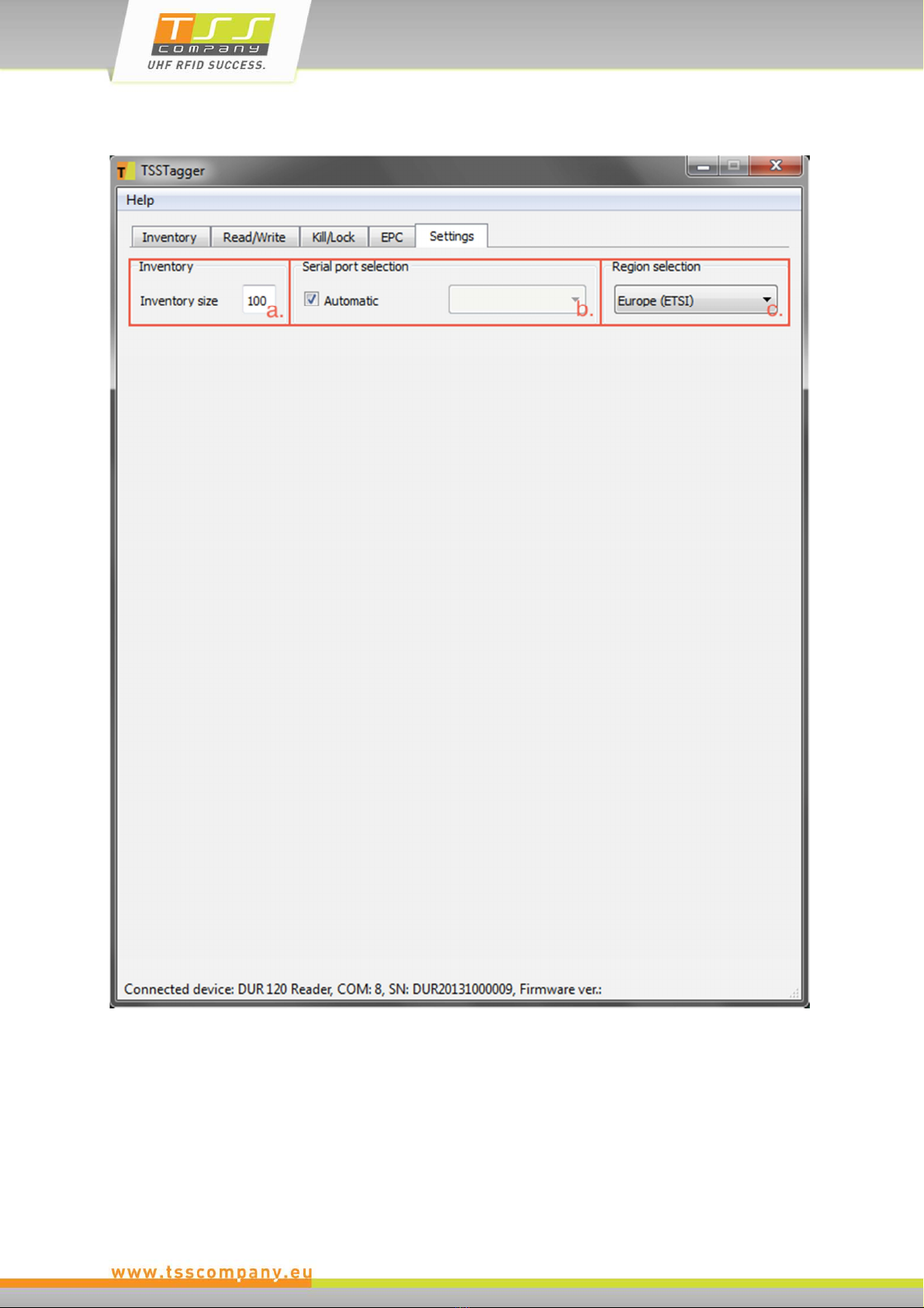
5.6 Settings Tab
a. Inventory:
The inventory size defines the maximum number of EPC numbers listed in the
inventory list. If the inventory size limit is reached the oldest EPC numbers are
discarded. This also happens if inventory size gets decreased.

b. Serial port selection:
The default setting for serial port selection is Automatic, so the application tries
to find the device connected to the computer. In case of any problems, the
automatic COM port selection can be overridden, enabling the user to choose the
device manually.
c. Region Selection:
Supported only by mURM Evaluation Board.

6. TSSUpdater
6.1 Installation
-Extract the contents of TSSUpdater.zip into the program directory.
-Double-clic vcredist_x86.exe to begin the setup of Microsoft Visual C++ 2013 x86
Redistributable software pac age
-The setup program guides you through the installation.
-Wait until Microsoft Visual C++ 2013 x86 Redistributable software pac age has been
successfully installed.
6.2 Firmware update
-Connect the device to a PC via a USB connection. (A USB to Serial driver has to be
installed on the PC)
-Run TSSUpdater.exe from the program directory.

-Clic the Update firmware button. The firmware file selection dialog will appear.
-Select the desired firmware file and clic Open. The Update firmware dialog will
appear.

-Clic OK in Update firmware dialog. The firmware update process will start shortly.
-Wait until the “Firmware update Successful” message appears in the status bar.

6.3 Troubleshooting
System Error
This error can occur if one of the required DLLs is missing from the program directory, or
when the Microsoft Visual C++ 2010 x86 Redistributable software pac age is not
installed.
Extract the contents of TSSUpdater.zip into the program directory and install the
Microsoft Visual C++ 2010 x86 Redistributable software pac age.
Bad Frames integrity
This error can occur if the firmware file is corrupted.
Obtain a new copy of the firmware file.
Serial port error
This error can occur when opening a session while using a serial port.
Restart the application or unplug your device and plug it bac in again.
Firmware update error
This error can occur if the device was accidently unplugged before the update process
has finished or because of a communications error between the device and the
connected computer.
Start the firmware update process again.
Error 33
This error can occur in the rare situation of the device firmware being faulty.

Disposal of the product
Do not dispose of the product in municipal or household waste. Please
check your local regulations for proper disposal and/or recycling of
electronic products.
Table of contents
Other TSS RFID System manuals

Popular RFID System manuals by other brands

Feig Electronic
Feig Electronic OBID i-scan ID ISC.LRM2500-A installation manual

Nordic ID
Nordic ID AR62 user guide

Sanela
Sanela SLZA 30A Instructions for use

Elatec
Elatec TWN4 MultiTech 2 HF user manual

Feig Electronic
Feig Electronic ID RED.M50-E installation manual

Zephir
Zephir 2200 Traditional Series quick start guide


Balluff
Balluff IO-Link BIS M-4A3-082-401-07-S4 Assembly instructions

Emka Electronics
Emka Electronics Swing Handles Series quick start guide

Emka Electronics
Emka Electronics Swing Handles Series quick start guide

HID
HID iCLASS SE RB25F user guide

Transmitter Solutions
Transmitter Solutions Dolphin UHF-R1 user manual

Honeywell
Honeywell IH45 user guide