Tube Amp Doctor Tweed One-Twelve-16 User manual

Tube Amp Doctor GmbH, Germany www.tubeampdoctor.com
WARNUNG
ACHTUNG:
diese Bausätze sind keine Anfängerprojekte! Die Spannungen in einem Röhrenverstärker
können 500V und mehr betragen und sind somit bei unsachgemäßer Handhabung absolut
lebensbedrohlich!!!
Wir liefern lediglich eine komplette Zusammenstellung der benötigten Bauteile sowie einen
Schalt- und Layoutplan. Tube Amp Doctor bietet keinen grundsätzlichen Support für den
Aufbau an! Die Bausätze und deren Bestandteile sind sorgfältig geprüft und die zugrunde
liegenden Schaltungen sind seit über 40 Jahren in Gebrauch.
Für die Funktion der vom Kunden aufgebauten Geräte übernehmen wir keine Gewähr (für
die Bauteile selbst natürlich schon). Sollte der Aufbau zu unerwarteten Schwierigkeiten
führen, so kann die Tube Amp Doctor GmbH den Bausatz im Kundenauftrag fertig aufbauen
oder ggf. andere Service-Techniker vermitteln.
Fragen zu den Bausätzen werden wir auf der Tube Amp Doctor Web-Site unter FAQ
zusammenstellen um so ggf. Hilfestellung zu leisten.
WARNING
ATTENTION:
Please note that the Amp-Kit are not a beginners project but for experienced amp builders!
Voltages inside tube amplifiers can exceed 500V and can cause serious damage and can
even kill!
We only supply a complete compilation of excellent parts, a schematic and a layout
plan. Tube Amp Doctor does not offer a general support for you DIY project.
We do not warranty for what you build out of the supplied components. If you get stuck with
your DIY project then TAD might offer to finish assembly of your kit based on your service-
order or refer you to a skilled technician. Questions and answers about the AMP-KITS will
get collected and published at the F.A.Q. section at www.tubeampdoctor.com.

- 1 -
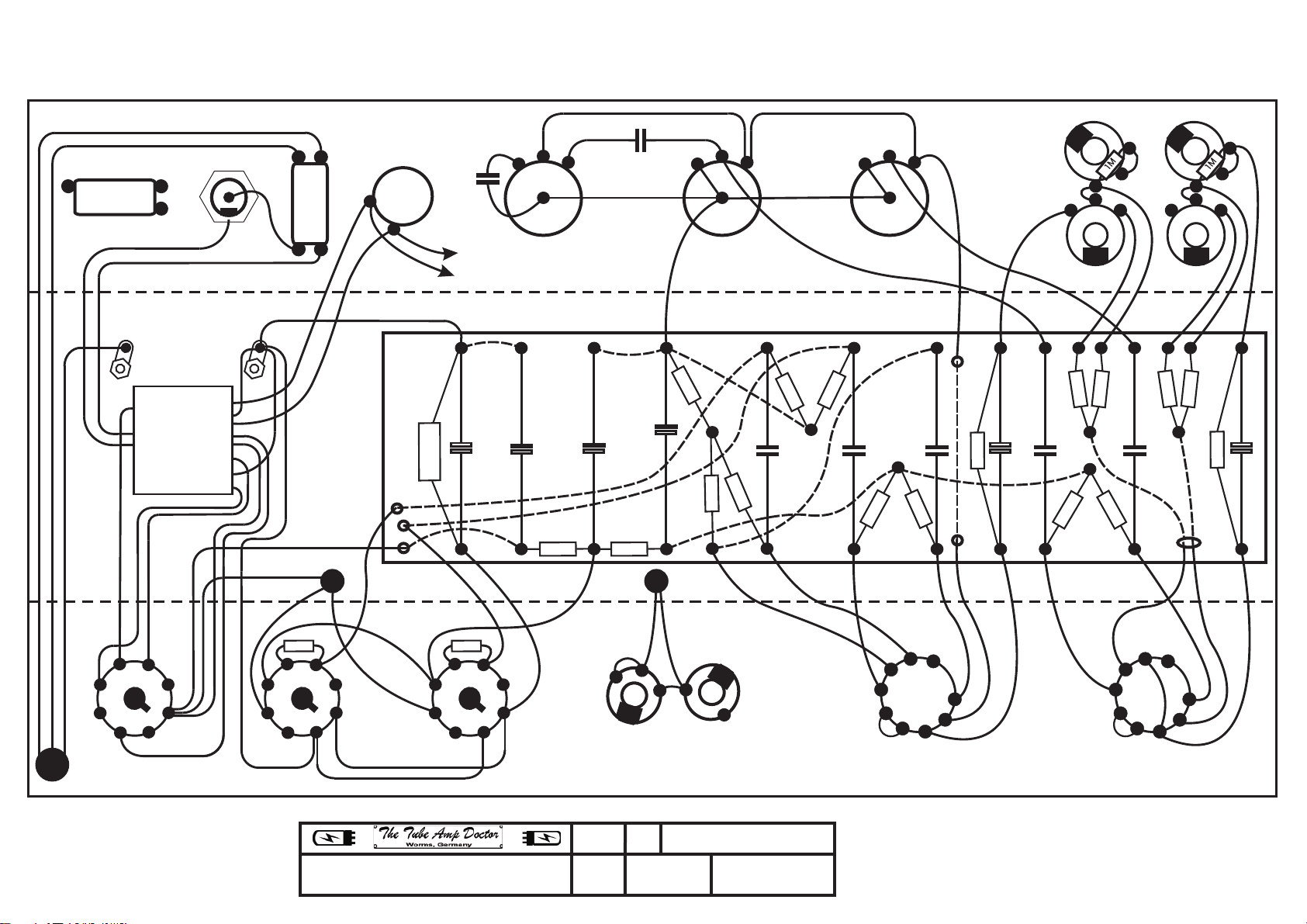
Verarbeitungvorschlag Tweed One-Twelve-16 Amp Kit
1. Materialien auspacken und auf Vollständigkeit prüfen.
2. Fehlende Löcher in das Chassis bohren: 2x für Lötleiste und 1x seitlich mittig
Trafoseite für Kabelhalter.
3. Mit der Bestückung des Boards beginnen: zuerst Widerstände (0,5W),
Leistungswiderstände, Kondensatoren, zuletzt Elektrolytkondensatoren. Auf
korrekte Polarität achten.
4. Kabelverbindungen und Brücken unter dem Board herstellen.
5. Board ausrichten und durch die vorhandenen Löcher im Chassis anzeichnen und
bohren. (3,5mm)
6. Kabelverbindungen, die unter dem Board beginnen zu anderen Teilen lt.
beiliegender Liste herstellen.
7. Trafo und Terminal Solder Lockwasher Lugs für Massestellen montieren.
8. Röhrensockel montieren: auf korrekte Orientierung achten
9. Trafo lt. beiliegenden Plänen anschließen, sekundäre Leitungen verdrillen.
10.Lampenhalter, Sicherungshalter montieren
11.Poti mit Zahnscheiben montieren (Orientierungsnase umbiegen)
12.Eingangsbuchsen vorverdrahten und anschließend mit U-Scheibe montieren.
13.Lautsprecherbuchsen montieren
14.Durchführtüllen einsetzen, 2x 10mm für Übertrager, 1x 15mm für Netzkabel)
15.Übertrager montieren, Kabel durchführen. Blau und Braun verdrillt anschließen.
16.Board einsetzen, ausrichten und befestigen.
17.Leitungen vom Board zu den anderen Betriebsmitteln lt. Verdrahtungsplan
herstellen.
18.Netzkabel ca. 10cm abisolieren und anschließen.
19.Heizleitung verdrillt verlegen, grünes Kable, 18AWG. (Punkte „F“und „F1“im
Layout)
20.Cabinet auf den Kopf stellen, Chassis einschieben und Rückwand anlegen um
Bohrlöcher anzuzeichnen.
21.Angezeichnete Bohrlöcher mit 5,5mm bohren.
22.Lautsprecher montieren.
23.Chassis in Cabinet montieren.
24.Lautsprecherkabel herstellen und an Speaker montieren.
25.Zugentlastung mit Netzkabel seitlich am Cabinet montieren
26.Röhren einsetzen.
27.Funktionsprüfung: Sichtkontrolle: Verdrahtung korrekt? Alle Massestellen
angeschlossen? Elkos mit korrekter Polarität? Röhrensockel korrekt verdrahtet?
Erde korrekt und sicher ausgeführt? Isolationen der Kabel nicht beschädigt?
28.Elektrische Funktionsprüfung: Multimeter: Massepunkte haben Verbindung zum
Chassis, Keine Kurzschlüsse?

- 2 -
29.Nach Möglichkeit Primärspannung langsam hochfahren, dabei Spannungen
überprüfen.
30.Ohne Variac: Alle Regler auf Voll: Gerät einschalten: Rote Kontrollleuchte geht
sofort an, Hochspannung (gemessen an erstem Elko ist 0V) Diese steigt innerhalb
von ca. 20 sec auf ca. 490V um dann langsam auf ca. 400V zu sinken. Die
Spannung an der Kathode der Endröhren (Pin 8) steigt dabei langsam auf ca.
22V. Jetzt muss der Amp rauschen, wenn nicht sofort wieder ausschalten und
zurück zu Punkt 27.)
31.
Backpanel anschrauben

- 1 - 12.05.2015
Tweed One-Twelve-16 Amp Kit Assembly-Instructions
1. Unpack all material and check for completeness.
2. Drill the missing holes into the chassis: 2x for the soldering strip and 1x sideways and
centric on the side of the transformer for the cable holder.
3. Commence equipping the board: first the resistors (0.5W), power resistors,
capacitors, and lastly the E capacitors. Pay attention to correct polarity.
4. Set up cable connections and bridges underneath the board.
5. Adjust the board, mark the chassis holes and drill (3.5mm).
6. Set up cable connections from under the board to other parts, according to enclosed
list.
7. Mount transformer and Terminal Solder Lockwasher Lugs for earth/ground point.
8. Mount tube sockets; pay attention to correct orientation.
9. Connect transformer according to scheme, twist the secondary wires.
10.Mount lamp holder and fuse carrier.
11.Mount potentiometers with chopper discs and bend the lug.
12.After Pre-wiring the input jacks mount them with the washer.
13.Mount the speaker output jacks.
14.Insert rubber grommets (2x 10mm for the transformer, 1x 15mm for power cord)
15.Mount the transformer, feed the cable through. Twist blue and brown and connect.
16.Insert the board, adjust it and fix it.
17.Wire everything according to scheme.
18.Skin power cord for about 10cm and connect it.
19.Twist and install the green filament cable, 18AWG. (Positions “F” and “F1” of the
layout)
20.Turn the cabinet upside down, slide in the chassis and adjust the back panel in order
to draw the drill holes.
21.Drill the holes at 5.5mm.
22.Mount the loudspeakers.
23.Mount the chassis into the cabinet.
24.Connect the loudspeaker cable to the speaker.
25.Mount the power cord at the side of the cabinet using the cable relief.
26.Plug in the tubes.
27.Functioning test: visual check: wiring correct? Have you connected every earth point?
Do the electrolytic capacitors have the correct polarity? Are the tube sockets correctly
wired? Grounding safe and correct? Are the cable insulations undamaged?
28.Electronic functioning test with multimeter (Ω): do all earth points have connection to
chassis, do all points carrying high voltage have no shorts to ground?
29.If possible, while gradually increasing the voltage, measure the voltage.

- 2 - 12.05.2015
30.Without variac: turn all controls up to max. Switch on device: red pilot light should turn
on immediately, high voltage (measured at the first electronic capacitor is 0V) should
rise up to about 490V within 20 seconds and then slowly sink down to about 400V.
The voltage at the cathode of the power tube (Pin 8) should slowly rise to circa 22V.
Now, the amp should make a steady hiss. If not, switch off the device immediately
(!!!) and go back to point 27. Conduct functioning test again thoroughly.
31.Screw on the back panel.


Drawing: Drawn: Date:
Tweed One-Twelve-16 Layout SM 12.09.18
ãTAD: For private use only
Do not copy
6452L #70005
Scale: Units:
None Mm 1.41
AC-Inlet
V4
Pilot-
Light
1
2
3
4
56
7
8
1K5
F
F1
1
2
3
4
56
7
8
1K5
F
F1
1
2
3
4
56
7
8
1
2
4
5
6
79
3
8
F
F1 V2
1
2
4
5
6
79
3
8
F
F1 V1
1M
1M
Spkr. Ext. Spkr.
25uF/25V BP
25uF/25V BP
+
16uF/475V
+
16uF/475V
+
16uF/475V
22nF
0,1uF
25uF/25V BP
270R/5W
0,1uF
0,1uF
0,1uF
100K
100K
68K
68K
68K
68K
1K5
100K
56K
220K
220K
56K
1K5
1M
5K1 22K
820R
500pF
5nF
To all 6,3V Heaters:
18 AWG, twisted
PIN 2, 7 : 6V6
PIN 4-5, 9: 12AX7
Red
Yellow
Green
White
Black
Grey
Yellow
Black
Red
Brown
Blue
Green/Yellow
Brown
Blue
A1M A1M
A1M
Bright Normal
VolumeVolume
ToneGround Fuse On
V3
V5
Unused
Wires are CB3035, Yellow 22AWG
Dotted wires run under the board
Twist all wires of the power transformer and
blue/brown of AC inlet cable.
not specified
Green
Red
Green/Yellow
Yellow
Yellow
Green
Green
Red
Red
Grey
Black
White
AWG18 stripped
Green/Yellow


Table of contents
Languages:
Other Tube Amp Doctor Amplifier manuals