audere CLASSIC PREAMP User manual

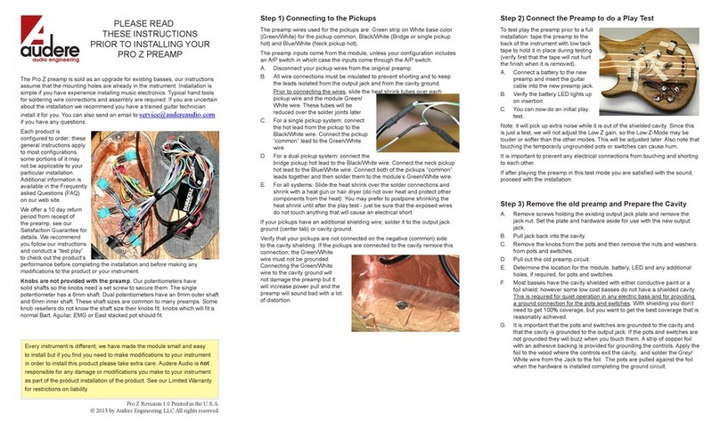
Step 2) Connect the Preamp to do a Play Test
To test play the preamp prior to a
full installation: tape the preamp
to the back of the instrument with
low tack tape to hold it in place
during testing (verify rst that the
tape will not hurt the nish when it
is removed).
Note: it will pick up extra noise
while it is out of the shielded
cavity. Also note that touching the
temporarily ungrounded pots or
switches can cause hum.
It is important to prevent any
electrical connections from touching and shorting to each other.
Step 3) Remove the old preamp and Prepare the Cavity
A. Remove screws holding the existing output jack plate and remove the
jack nut. Set the plate and hardware aside for use with the new jack.
Pull jack back into the cavity.
B. Remove the knobs from the pots and then remove the nuts and washers
from pots.
C. Pull out the old preamp circuit.
D. Determine the location for the new module, battery.
E. Most basses have the cavity shielded with either conductive paint or a
foil shield; however some low cost basses do not have a shielded cavity.
This is required for quiet operation in any electric bass and for providing
a ground connection for the controls. With shielding you don’t need to get
100% coverage, but you want to get the best coverage that is reasonably
achieved.
F. It is important that the pots and switches are grounded to the cavity and
that the cavity is grounded to the output jack. If the pots and switches are
not grounded they will buzz when you touch them.
Installing a cooper foil shield is easy. Copper foil is available with glue on
the back (like tape) and you simple apply it to the wood. If your copper
tape does not have a special conductive adhesive then solder the strips of
copper tape together at all joints. A simple small tack joint of solder at one
spot per joint is all that is required. Conductive paint is also available to
shield instruments but copper works better.
Step 4) Installing Pots
The pots are all 100K Ohm with audio taper for volume pots and linear taper
for tone and balance pots. Pots turn clockwise for the maximum setting.
Single pots have an M7 bushing which ts in a 7mm mounting hole.
Stacked/dual pots have an M9 bushing and t in a 9mm
mounting hole.
A. If your existing holes are larger than the single pot’s
bushing size: An oversized washer has been provided
for use in the cavity interior if required. This larger washer
goes over the shaft rst. Then add the two rubber spacer
rings that t over the shaft; these go up into the standard
sized hole to center the pot shaft.
B. Orient the control as is desired, then secure each pot with a washer and
panel nut on the face of the bass.
Do not attempt to solder to the pot’s metal bushing.
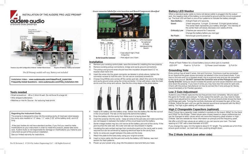
Step 1) Connecting to the Pickups
The preamp wires used for the pickups are: Green strip on White base color
(Green/White) for the pickup common, Black/White (Bridge pickup hot) and
Blue/White (Neck pickup hot).
A. Disconnect your pickup wires from the original preamp.
B. All wire connections must be
insulated to prevent shorting and to keep
the leads isolated from the output jack
and from the cavity ground.
Prior to connecting the wires, slide
the heat shrink tubes over each pickup
wire and the module Green/White wire.
These tubes will be reduced over the
solder joints later.
C. If you have active pickups - see required mod listed on page 2.
Connect the Bridge pickup hot lead to the Black/White wire.
Connect the Neck pickup hot lead to the Blue/White wire.
Connect both of the pickups “common” leads together and then solder them
to the module’s Green/White wire.
D. Slide the heat shrink over the solder connections and shrink with a
heat gun or hair dryer (do not over heat and protect other components from
the heat). You may prefer to postpone shrinking the heat shrink until after
the play test - just be sure that the exposed wires do not touch anything that
will cause an electrical short.
If your pickups have an additional shielding wire; solder it to the output jack
ground (center tab) or cavity ground.
Verify that your pickups are not connected on the negative (common) side
to the cavity shielding. If the pickups are connected to the cavity remove
this connection; the Green/White wire must not be grounded. Connecting
the Green/White wire to the cavity ground will not hurt the preamp but it will
sound bad with a lot of distortion.
The Z-Mode preamp is sold as an upgrade for existing basses and our
instructions assume that the mounting holes are already in the instrument.
Typical hand tools for soldering wire connections and assembly are
required. If you are uncertain about the installation we recommend you have
a trained guitar technician install it for you. You can nd information in the
Frequently asked Questions (FAQ) page on our web site or send an email to
Every instrument is different; if you find you need to make modifications
to your instrument in order to install this product please take extra care.
Audere Audio is not responsible for any damage or modifications you
make to your instrument as part of the product installation of the product.
See our Limited Warranty for restrictions on liability.
CLASSIC PREAMP
INSTALLATION GUIDE
PLEASE READ
Your new Audere preamp features:
Ultra Low Distortion
Low Noise
High Quality Pots and Parts
Active Balance & Volume Control
4 Bands of Tone Control
Low Power consumption on 9 or 18 Volts
The operation of the pots is written on the back of the pots. For example, T/B
would be a stacked Treble/Bass. The codes we use include:
Vol – Volume
Bal – Balance
V/B – Volume / Balance
HM – High Mid
LM – Low Mid
M/M – High Mid / Low Mid
Bass – Bass range
Treb – Treble range
T/B – Treble / Bass

Step 5) Output Jack
Tab 1-top) Jack Audio Out - White wire
Tab 2) Jack Ground - center tab: 2-3 Grey/White
wires. The loose Grey/White wire connects to
your Cavity Ground.
Tab 3) Jack Negative - Black wire
Secure the jack plate with the original hardware or with the hardware
provided on the jack. Set the depth of the jack using an internal panel nut, if
required. Reinstall the plate with the original screws
Be aware that when the cable to the amplier is partially inserted into the
jack, the center connector gets the full battery voltage. This is the most
common jack used with active basses and this characteristic is well known.
The shielded cavity and bridge ground wires need to be connected to the
output jack center tab. The output jack has an extra unattached ground wire
for this use. Slide heat shrink over the Grey/White wire, then solder this
wire to the Bridge and cavity ground wires. Slide the heat shrink over the
solder joint and shrink.
Step 6) Final Installations Details
A. Apply one of the adhesive pads to the base of module; remove the rst
liner, press in place, remove the 2nd liner and press the module into
position in the cavity.
B. Install the battery.
C. Re-Install the electronic cavity cover and attach your knobs.
D. Our potentiometers have solid shafts so the knobs need a set screw
to secure them. The single potentiometer has a 6mm shaft. Dual
potentiometers have an 8mm outer shaft and 6mm inner shaft.
The knobs are a standard set screw style & size, available at online retailers
and on Audere’s web site.
MODS: SINGLE PICKUP INSTRUMENTS
It is easy to modify the preamp to work with only 1 pickup:
A. Solder the Blue/White wire to the Green/White wire.
B. Remove the wires from the Balance Pot.
C. Solder the Black/Orange wire to the Orange wire.
D. Cut off the excess White/Orange wire (there’s no connection made to it).
E. Cover the 3 wires with heat shrink.
Version 4 Printed in the U.S.A.
© 2014 by Audere Engineering LLC All rights reserved.
SATISFACTION GUARANTEE
If within 10 days after delivery the purchaser decides for any reason to
return the product, Audere will refund the purchase price of the product
subject to the following conditions: return the product in new condition;
follow the shipping instructions under the Limited Warranty section; refunds
will issued to the purchaser by the original payment method; and refunds do
not include shipping and handling.
LIMITED WARRANTY
What this warranty covers:
Audere Audio warrants its Products to be free from defects in materials and
workmanship for one year from the purchase date and is available to the
original purchaser.
The limited warranty does not cover:
· Damage caused by misuse or abuse;
· Exposure to environmental extremes;
· Products that have been modied;
· Shipping damages of any sort;
· Damage due to use that is not in conformity with factory specications;
· Normal wear and tear or parts intended to be replaced due to normal use;
· Claims based on the subjective issue of tonal characteristics;
· Product if the serial number has been defaced, modied, or removed.
What Audere Audio will do:
If, in our sole determination, the defect is covered by the Limited Warranty,
Audere Audio will promptly repair or replace the product, at our option, and
return it prepaid to the purchaser. If the defect is not covered or is excluded
from this Limited Warranty it will be returned without repair or replacement,
shipping and insurance to be paid by purchaser.
AUDERE ENGINEERING IS NOT LIABLE FOR MODIFICATIONS MADE
TO YOUR INSTRUMENT EVEN IF THOSE MODIFICATIONS WERE MADE
TO FACILITATE PRODUCT INSTALLATION. YOU SHOULD EVALUATE
THE PRODUCT FULLY PRIOR TO A FULL INSTALLATION.
IN NO EVENT SHALL AUDERE AUDIO BE LIABLE FOR INDIRECT,
INCIDENTAL, OR CONSEQUENTIAL DAMAGES. THIS LIMITED
WARRANTY IS GIVEN AS YOUR EXCLUSIVE REMEDY AND IS MADE
IN LIEU OF ALL OTHER WARRANTIES, EXPRESS OR IMPLIED. ALL
IMPLIED WARRANTIES, INCLUDING WITHOUT LIMITATION, ANY
IMPLIED WARRANTY OF MERCHANTABILITY OR FITNESS FOR
A PARTICULAR PURPOSE, ARE HEREBY EXPRESSLY LIMITED IN
DURATION TO THE DURATION OF THIS WRITTEN WARRANTY
In the case of conicting terms and conditions between this Limited
Warranty and any purchase order, contracts or invoices, this Limited
Warranty is the controlling document.
Shipping instructions:
1. Contact Audere Audio within the warranty period and obtain a Return
Authorization (RA) number and ship to address prior to shipping.
2. Package the product for safe shipping. Mark the RA number prominently
on the outside of the box.
3. Include inside the box the RA number, your name, and address.
4. Ship the product prepaid and insured within 14 days of the RA date.
Your rights under state law:
This limited warranty gives you specic legal rights and you may have other
rights which vary from state to state; for example some states do not allow
all of the limitations on warranties.
Audere Audio
www.audereaudio.com
MODS: ACTIVE PICKUPS
From Step 1C. This is a modication
needed for active pickups only!
330 nF caps are soldered to each preamp
input wire then to the pickup output wire.
1) Solder the preamp Black/White wire to a
cap lead. Repeat, soldering the preamp
Blue/White wire to the 2nd cap (see picture).
2) Connect the Bridge pickup hot lead to
bare leg on the cap that has the Black/White
wired attached.
3) Connect the Neck pickup hot lead to the bare leg on the cap that has the
Blue/White wire attached.
5) Insulate the preamp Green/White wire - it will not be used.
6) Connect both of the pickups “common” leads together and solder them to
ground or connect to the Grey/White wire. This will have been already done
if installing into a previously working bass.
NOTE: NOISE COLLECTED BY THE PICKUPS
Our preamps are signicantly more accurate at capturing and amplifying
All of the Details of your signal. This is why the true tone of the instrument
is revealed with greater richness. If your bass is not properly shielded you
my nd the apparent noise has increased. Our preamps can not tell the
difference from external noise sources and the critical subtle details of your
playing as both create a signal at the input of the preamp.
If you are interested in upgrading your shielding, we have posted on the
Audere Audio web site some usable ideas and recommendations on how
you can to do it pretty easily. The most important step is shielding the pickup
cavities which often isn’t done; for example, some bass builders think it
doesn’t help to shield hum canceling pickups which isn’t true.
You can push the noise oor down further as you increase the time and
effort you put into it but a modest investment in shielding typically yields a
good balance between the results achieved and time invested.
Other audere Amplifier manuals
Popular Amplifier manuals by other brands

Behringer
Behringer Ultracoustic ACX900 Technical specifications
McIntosh
McIntosh MC150 owner's manual
Audio Authority
Audio Authority HDMI 1398B user manual
Universal Audio
Universal Audio LA-610 MkII manual
Pioneer
Pioneer SA-7100 KUW Service manual
On-Q/Legrand
On-Q/Legrand lyriQ IS-0336 Instruction/installation sheet
