www.turnerbiosystems.com
III. Setting up the GloRunner™ Microplate Luminometer
Procedure
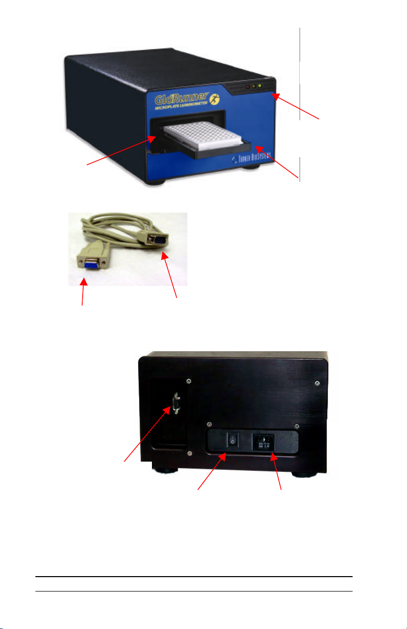
1. Position the instrument on a flat surface. Leave enough room for the sample
tray to extend in front of the unit (approximately 7 inches).
2. Plug in the unit. In some countries, the power plug provided may not match
the wall connection. If this is the case, you can use the appropriate power
cord if the input power is between 100 and 240 volts AC, and the nominal
frequency is between 50 and 60 Hz.
3. From your own computer, install the software according to the instructions
in Appendix A.
4. Connect the 9-pin serial cable between the luminometer and the computer.
The male 9-pin connector attaches to the GloRunnerand the female 9-pin
connector attaches to your computer (See Figure 2).
5. Turn on the power switch (rear of unit).
Note: The sample tray opens and closes via the software user interface. To
open the sample tray, please proceed to the next section for further
instructions.
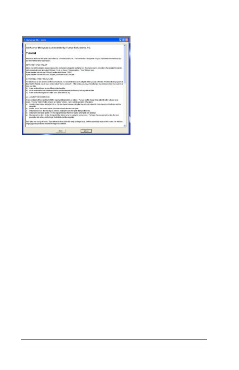
IV. GloRunner™ Microplate Luminometer DXL Software
Overview
The GloRunnerMicroplate Luminometer DXL software is very easy to use.
This direct-to-Excel based software is designed to give the user flexibility in
data retrieval, storage, and manipulation while using the GloRunner
Microplate Luminometer. User-defined protocols can be stored as templates for
easy retrieval of stored settings. For added help while using the GloRunner
DXL software, a tutorial is available. You will see the following dialog box
after clicking on the GloRunnericon from your desktop (an alternate way of
accessing the GloRunnerDXL software is through the program manager):
Figure 4