twin city ES-52 Instruction manual

Contents
Introduction . . . . . . . . . . . . . . . . . . . . . . . . . . . . . . . . . . . 1
Shipping and Receiving . . . . . . . . . . . . . . . . . . . . . . . . . . 1
Handling . . . . . . . . . . . . . . . . . . . . . . . . . . . . . . . . . . . . . 1
Short Term Storage . . . . . . . . . . . . . . . . . . . . . . . . . . . . . 2
Long Term Storage. . . . . . . . . . . . . . . . . . . . . . . . . . . . . . 2
Foundations and Supporting Structures. . . . . . . . . . . . . . 2
Fan Installation
Factory Assembled Units. . . . . . . . . . . . . . . . . . . . . . . 2
Disassembled Units. . . . . . . . . . . . . . . . . . . . . . . . . . . 2
Fan Operation – Safety . . . . . . . . . . . . . . . . . . . . . . . . . . 3
Operation Checklist . . . . . . . . . . . . . . . . . . . . . . . . . . . . . 4
Maintenance of Fans . . . . . . . . . . . . . . . . . . . . . . . . . . . . 4
General Motor Maintenance . . . . . . . . . . . . . . . . . . . . 4
Drive Maintenance. . . . . . . . . . . . . . . . . . . . . . . . . . . . 5
Bearing Maintenance. . . . . . . . . . . . . . . . . . . . . . . . . . 5
Lubrication . . . . . . . . . . . . . . . . . . . . . . . . . . . . . . . . . 5
Wheel and Shaft Maintenance. . . . . . . . . . . . . . . . . . . 6
Structural Maintenance . . . . . . . . . . . . . . . . . . . . . . . . 6
Troubleshooting Guidelines . . . . . . . . . . . . . . . . . . . . . . . 6
Troubleshooting Performance Problems
Air Capacity Problems. . . . . . . . . . . . . . . . . . . . . . . . . 6
Noise Problems. . . . . . . . . . . . . . . . . . . . . . . . . . . . . . 6
Vibration Problems . . . . . . . . . . . . . . . . . . . . . . . . . . . 7
Motor Problems. . . . . . . . . . . . . . . . . . . . . . . . . . . . . . 7
Drive Problems . . . . . . . . . . . . . . . . . . . . . . . . . . . . . . 7
Bearing Problems . . . . . . . . . . . . . . . . . . . . . . . . . . . . 7
Limitation of Warranties and Claims. . . . . . . . . . . . . . . . . 8
Introduction
The purpose of this manual is to provide instructions that
complement good general practices when installing or oper-
ating fans manufactured by Twin City Fan & Blower. It is the
responsibility of the purchaser to provide qualified person-
nel experienced in the installation, operation, and mainte-
nance of air moving equipment.
Instructions given in the body of this manual are general
in nature and apply to a variety of models manufactured by
Twin City Fan & Blower. Most units can be installed and
maintained with the instructions given.
Special applications may require additional information.
These instructions are supplied in the form of attached
appendices. Use the instructions in the appendix if the direc-
tions in this manual differ from instructions in the appendix.
As always, follow good safety practices when installing,
maintaining and operating your air moving equipment. A
variety of safety devices is available. It is the user’s respon-
sibility to determine adequate safety measures and to obtain
the required safety equipment.
Shipping and Receiving
All Twin City Fan & Blower products are carefully construct-
ed and inspected before shipment to insure the highest
standards of quality and performance.
Compare all components with the bill of lading or pack-
ing list to verify that the proper unit was received.
Check each unit for any damage that may have occurred
in transit. Any damage should be reported immediately to
the carrier and the necessary damage report filed.
Handling
Handling of all air moving equipment should be conducted
by trained personnel and be consistent with safe handling
practices. Verify the lift capacity and operating condition of
handling equipment. Maintain handling equipment to avoid
serious personal injury.
Units shipped completely assembled may be lifted with
slings and spreader bars. Use well-padded chains, cables
or nylon straps. On most units, lifting lugs are provided for
attaching chains (see Figure 1). Lift the fan in a fashion that
protects the fan and fan coating from damage. Never lift a
fan by the inlet or discharge flange, shafting or drives, wheel
or impeller, motor or motor base, or in any other manner that
may bend or distort parts.
Partial or disassembled units require special handling. All
parts should be handled in a fashion which protects the
coatings and parts from damage. Components should be
handled such that forces are not concentrated and bending
or distortion cannot occur.
Housings should be lifted using straps and spreaders. Do
not distort housing or side plates when lifting.
Bearing pedestals should be lifted using straps or
padded chains. Under no circumstances should an
attached or separated bearing pedestal be lifted by the
shaft, bearings, drives, motor
or wheel.
The shaft and wheel
assembly may be lifted
using a hoist and a spreader
with a sling around the shaft
at points nearest the wheel
(see Figure 2). Take care not
to scratch the shaft where
the wheel or bearings will be
mounted. Never lift or sup-
port the assembly by the
wheel. Always support the
assembly by the shaft when
lifting or storing. Do not sup-
Figure 1. Lifting Lug Locations
Figure 2. Moving Shaft and
Wheel with Spreader Bar
Lifting Lugs
Lifting Lugs
INSTALLATION, OPERATION & MAINTENANCE MANUAL
Centrifugal Fans
ENGINEERING SUPPLEMENT
ES-52
Issue Date: 1-1-94
Rev. Date: 1-24-01

2TCF&B ES-52
port the shaft or the wheel on housing sides. Use only the
key provided with the shaft and wheel.
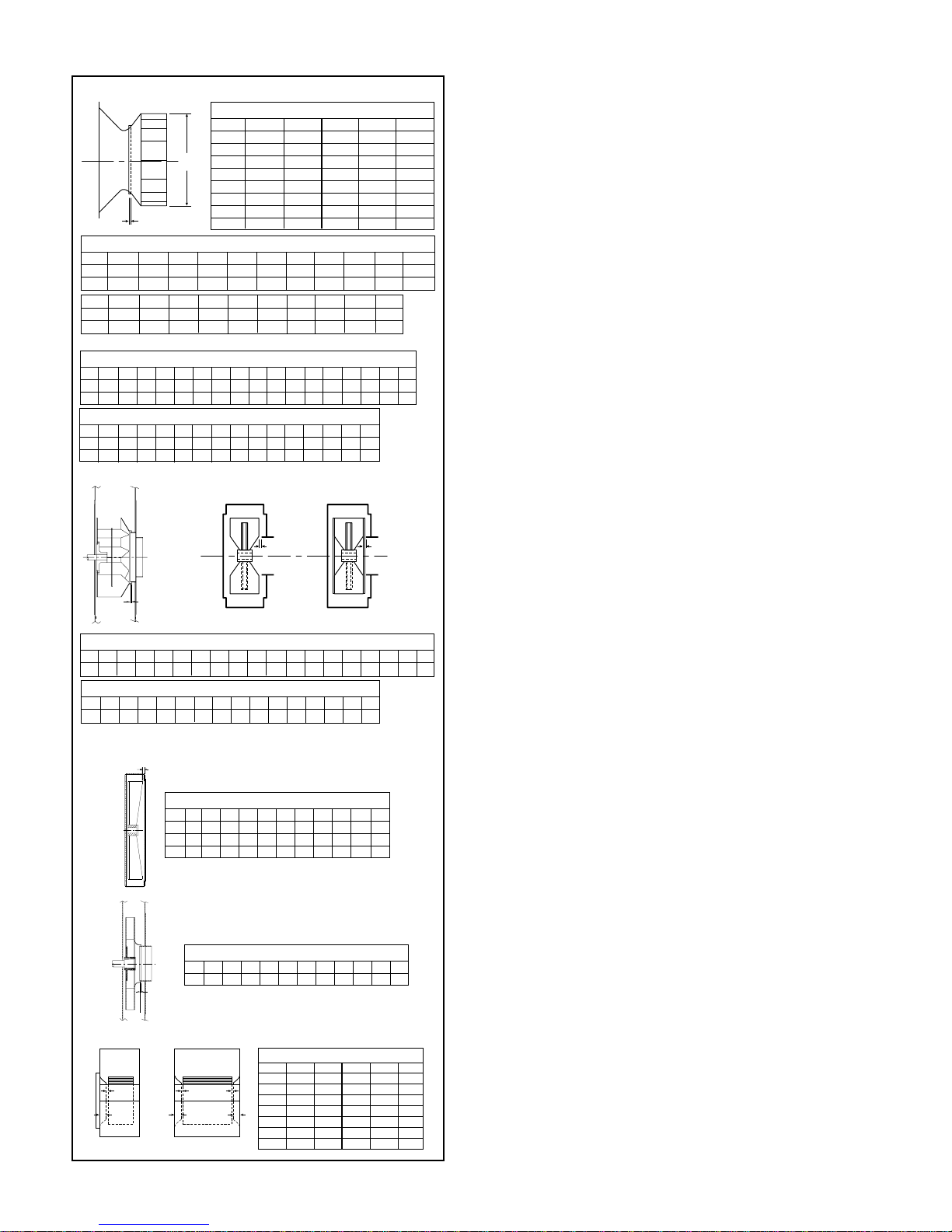
Wheels shipped separately can be lifted by slings running
through the blades and around the hub. Never lift the wheel
by blades or flanges. Always transport wheels by lifting. Do
not roll the wheel as this can damage coatings and change
the balance of the wheel.
Bent shafting is a source of vibration and bearing failure,
so handle the shaft with care. Any scratches on the shaft
may be removed with fine emery cloth or a stone.
Short Term Storage
If fan installation is to be delayed, store the unit in a pro-
tected area. Protect the fan and motor bearings from mois-
ture and vibration (or shock loading).
Long Term Storage
Prior to Storage — Fan bearings (and motor bearings per
the motor manufacturer’s specifications) are to be greased
at the beginning of extended storage. On belt driven units
the belt tension should be reduced to less than half the
specified value for the fan’s design to prevent a sag/set from
forming in the shafts and belts. If the unit was supplied with
a motor the motor windings should be meggered at this time
and recorded for comparison prior to placing in service. If
the fan housing was supplied with a drain connection, this
plug should be removed to prevent moisture from accumu-
lating in this portion of the unit during storage.
Storage — Fans should be stored indoors whenever possi-
ble where control over temperature, shock and dust is rea-
sonably maintained. If the unit is to be stored outside in the
elements, it should be covered with a water resistant mate-
rial. The bearings should be shielded individually from water
and dirt; however, do not tightly seal them to avoid trapping
condensation. Stored equipment should be housed on a
clean, dry floor or blocked up off the ground to prevent units
from sitting in any water or on the ground. If shock or vibra-
tion will be present during storage the unit may need to be
placed on some type of vibration dampening material to aid
in preventing brinelling of the bearing surfaces.
Periodic Check — On a monthly interval the equipment
should be checked to ensure that it has remained in an
acceptable stored condition. The fan (and motor if supplied)
should be rotated several times while adding enough grease
to replenish the bearing surfaces with fresh grease or to
maintain a full bearing cavity. Grease used must be com-
patible with that already supplied in the motor and fan bear-
ings. The fan impeller should be left at approximately 180
degrees from that of the previous month to prevent the shaft
and impeller from taking a set in one position. Storage
records should be maintained which indicate the above
requirements have been followed. Consult the motor manu-
facturer for proper storage, space heater connection and
lubrication if the unit was supplied with one.
Startup — When the unit is removed from storage all the
bearing grease should be purged and replenished with fresh
grease per lubrication decal. The motor should be meg-
gered to verify that the resistance is still at a satisfactory
level compared to the value recorded prior to storage.
Foundations and Supporting Structures
Floor mounted fans should be installed on a flat, level, rigid
concrete foundation with a mass at least three times that of
the assembly supported. The plan area should be no more
than twice that required by the equipment. Foundations with
larger areas should have correspondingly larger mass.
Anchor bolts should be “L” or “T” shaped with sufficient
length for nuts, washers, shims, and threads for draw-down.
Each bolt should be placed in a sleeve or pipe with a diam-
eter larger than the bolt to allow for adjustment.
Fans mounted to or within a structure should be placed
as close as possible to a rigid member such as a wall or col-
umn. The structure must be designed for rotating equip-
ment; static design for strength is not sufficient to insure
proper operation. Supports for suspended fans must be
cross-braced to prevent side sway. Structural resonance
should be at least 20% from fan operating speed. Vibration
isolators should be used where applicable.
Any ducting should have independent support; do not
use the fan to support ducting. Isolating the fan from duct-
work with flex connections eliminates transmission of vibra-
tion. Fans handling hot gases require expansion joints at
both the inlet and discharge to prevent excessive loads
caused by thermal growth.
Fan Installation, Factory Assembled Units
Follow proper handling instructions given earlier.
1. Move the fan to the final mounting position.
2. Remove skid, crates, and packing materials carefully.
3. If supplied, place vibration pads or isolation base on
mounting bolts. Line up holes in fan base with bolts.
4. Place fan on mounting structure. Carefully level unit using
shims as required at all mounting hole locations. Bolt
down the unit.
5. Any grout may now be used. Bolt the fan in position
before applying grout. Do not depend upon grout to sup-
port rotating equipment.
6. Continue with Operations Checklist.
Additional instructions may be given for some fan models,
components and accessories in the appendix.
Fan Installation – Disassembled Units
A unit is considered “disassembled” if any component
required for proper operation is shipped or supplied sepa-
rately or in pieces. Reference earlier instructions concerning
proper handling of fan components.
Instructions for Mounting and Assembly of Unit:
1. Move lower housing/framework to mounting location.
2. If vibration pads or bases are used, place on bolts first.
Place lower housing assembly onto bolts.
3. Level and shim if required. Bolt into place.
4. If separated pedestal or bearing pedestal:
a. Bring bearing pedestal to desired location.
b. Place any vibration base or pads into place. Set bear-
ing pedestal on bolts.
c. Never distort bearing pedestal by forcing it to align
with a non-level surface. Shim beneath the pedestals
as required.
d. Check bearing centerline height. Change centerline
height to match centerline height of housing. High tem-
perature units may require the housing centerline to be
lower when cold so that it will be centered when hot.
e. Measure from housing to bearing pedestal to bring
bearing pedestal into square with housing (a large
square may also suffice).
f. Bolt into position.
5. Shaft and wheel assembly preparation:
a. Clean protective coating off shaft with solvent. Do

TCF&B ES-52 3
Figure 3. Drive Component Assembly
not touch clean areas of shaft with hands. Perspiration
can cause rust or pitting over time.
b. Remove keys from shaft.
c. Clean inside of wheel bore with solvent. Make sure set
screws will not interfere when inserting shaft into
wheel bore.
6. Arrangement 1, 9 or 10: Drive Component Assembly (See
Figure 3):
a. Insert shaft into wheel from back side of wheel.
b. When shaft is flush with wheel hub, put key into key-
way and tighten wheel set screws.
c. Insert shaft through opening in drive side. (If split
housed unit, lower into position.)
d. Install bearings onto shaft. Do not tighten bearing set
screws at this time. The bearing housing should be
perpendicular and the bearing base parallel to the axis
of the shaft to prevent loads caused by misalignment.
e. Mount assembly, bolt bearings to drive stand. Shaft
must be parallel with side of bearing pedestal. After
aligning and bolting bearings to pedestal, tighten
bearing set screws. Continue with step 8.
7. Arrangement 3 (Split-housed) units ( See Figure 4):
a. Parts on DWDI units are assembled in the following order
as viewed from opposite drive side: Bearing
bar assembly and opposite bearing, funnel, (housing
side), wheel, (housing side), funnel, drive side
bearing bar assembly, drive bearing and sheaves. Mount
bearingbar assemblyto housing.Center wheelin funnels.
b. Parts on SWSI are assembled in the following order as
viewed from opposite drive side: Bearing bar assembly
and opposite bearing, funnel, (housing side), wheel,
(housing side), drive side bearing bar assembly, drive
bearing and sheaves. Mount bearing bar assembly to
housing. (See Figure 6 for wheel-funnel overlap.)
c. Assemble parts in above order on shaft.
Shaft
Centerline
Bearing
Pedestal
Sheave
Bearing
Inlet Funnel
Housing Side
Wheel Assembled Bearing,
Shaft, Funnel, and
Housing. Frame
Angles Not Shown.
Figure 4. Split-housed Drive Component Assembly
d. Move assembly into position. Lightly bolt bearings
into place.
e. Shaft should be parallel with discharge of housing.
Move bearings to accommodate.
f. Level shaft; shim bearings if required. Tighten bearing
set screws.
8. Install motor on base. Carefully align shafts for drive
installation.
9. Mount drives as follows:
a. Slip (do not pound) proper sheave onto corresponding
shaft as close as possible to bearing. CAUTION:
PLACING FAN SHEAVE ON MOTOR CAN OVER-
SPEED WHEEL AND CAUSE STRUCTURAL FAIL-
URE.
b. Align sheaves with a straightedge
extended along perimeters of both
sheaves, just making contact in
two places on outside the perime-
ters of both sheaves (see Figure
5).
c. Tighten down sheave bolts.
d. Install a matched set of belts.
Slide the motor to obtain slack
and tighten belts. Using a pry
will damage belts.
e. Tighten belts to proper belt ten-
sion. Ideal tension is just
enough tension so that belts do
not slip under peak load.
Recheck sheave alignment.
f. After initial installation of belts,
recheck belt tension again after
a few days to adjust belt ten-
sion. (New belts require a break-
in period of operation.)
10. Install any safety devices or accessories supplied.
(Accessories commonly used are inlet vanes, shaft
seals and shaft coolers, plugs, dampers, and inlet or
discharge screens. Refer to appropriate documents in
appendix.)
11. Grout may now be applied. Grout is used to distribute
loads and should not be used as the sole support of
any rotating equipment.
12. When connecting the fan to the system, it is recom-
mended that the inlet and discharge be isolated from the
system with flex connections (where practical) to block
transmitted vibration. All duct connections to the fan
should be independently supported. Do not use fan to
support duct.
Fan Operation - Safety
For general safety practices for air moving equipment, see
AMCA Bulletin 410.
Twin City Fan & Blower has many safety accessories
available. These safety devices include (but are not limited
to) belt guards, shaft guards, inlet and discharge screens.
The use, abuse, or non-use of safety devices is the respon-
sibility of the purchaser.
Facility-related safety conditions include fan accessibility
and location. How easily can non-service personnel access
the unit? Is the fan in a hazardous duty environment? Was
the unit ordered for this duty? Other concerns must also be
addressed. All fans should be powered through switches
which are easily accessible to service personnel from the
Figure 5.
Sheave Alignment

TCF&B ES-524
A
DIA
B
RBO RBR
BB
B
A
B
A
B
A
SWSI DWDI
Figure 6. Wheel-Funnel Overlap
Note: On sizes 905-911 wheel is to be centered in housing.
RBW –Center wheel in housing.
RBO / RBR Wheel Placement
Size 913 915 917 919 921 923 926 929 933 937 941 945 949 954 960
B0.53 0.53 0.59 0.69 0.78 0.88 0.97 1.03 1.22 1.38 1.56 1.69 1.81 1.88 2.16
*Use dimension “B”for positioning wheel on SSI and TSL.
BC, BCS, TSL & BAF SWSI Wheel Placement
Size 122 135 150 165 182 200 222 245 270 300 330
A12.25 13.50 15.00 16.50 18.25 20.00 22.25 24.50 27.00 30.00 33.00
B0.32 0.34 0.38 0.44 0.56 0.63 0.69 0.75 0.88 0.97 1.06
APF – Straight Bore Hubs Wheel Placement
Size
121 141 161 181 201 221 251 281 321 351 391 441 491 551 631 711 791
A13.00 14.13 16.16 18.44 19.94 22.78 25.06 28.25 31.81 35.81 39.81 44.56 50.06 55.75 63.69 71.69 79.63
B0.25 0.25 0.25 0.31 0.31 0.31 0.50 0.50 0.56 0.63 0.63 0.75 0.78 0.81 1.03 1.28 1.38
Size 365 402 445 490 542 600 660 730 807 890
A36.50 40.25 44.50 49.00 54.25 60.00 66.00 73.00 80.75 89.00
B0.94 1.03 1.13 1.25 1.38 1.56 1.69 1.88 2.09 2.28
HIB, RTF, HRT Wheel Placement
Size A B Size A B
180 20.50 0.31 400 45.25 0.69
200 22.50 0.34 450 50.00 0.75
220 25.00 0.38 490 55.13 0.81
240 27.50 0.44 540 61.00 0.91
270 30.38 0.47 600 67.50 1.00
300 33.50 0.50 660 74.25 1.13
330 37.00 0.56 730 82.00 1.22
360 41.00 0.63 800 90.75 1.34
fan. Every switch should have the ability to be “locked-off”
by the service person and the key to be retained by this per-
son to prevent accidental power of the fan while service is
in process.
Operation Checklist
Verify that proper safety precautions have been followed:
Electrical power must be locked off.
Check fan mechanism components:
System connections are properly made and tightened.
Bearings are properly lubricated.
Wheel, drives and fan surfaces are clean and free of
debris.
Rotate the impeller by hand to verify it has not shifted
in transit.
Check wheel/funnel overlap. See Figure 6.
Drives on correct shafts (not reversed).
Check position of guards to prevent rubbing.
Check fan electrical components:
Motor is wired for proper supply voltage.
Motor was properly sized for power and rotational
inertia of rotating assembly.
Motor is properly grounded.
All leads are properly insulated.
Trial “bump”:
Turn on power just long enough to start assembly
rotating.
Check rotation for agreement with rotation arrow.
Does the assembly make any unusual noise?
(See Figure 7)
Check drive alignment and tension. Does this meet
with drive manufacturer’s recommendations?
Correct any problems which may have been found.
(Follow safety guidelines - shut power off). Perform
checklist again until unit is operating properly.
Run unit up to speed.
Verify fastener tightness. These may have loosened during
shipment or installation.
Set screws attaching wheel hub to shaft.
Set screws in drive sheaves or coupling.
Nuts on inlet funnel.
Nuts and bolts holding motor.
Nuts holding housing frame to base and base to
ground.
Nuts on accessories including shaft seal, access
doors and pie-splits.
Bolts in taper-lock bushings.
Grease line connections.
After one week of operation, check all nuts, bolts and set
screws and tighten if necessary.
Maintenance of Fans
This section contains general maintenance instructions for
your Twin City Fan & Blower unit. For specific information
about maintenance of components, particularly for special
application fans, see the attached documents.
General Motor Maintenance
The three basic rules of motor maintenance are:
1. Keep the motor clean.
2. Keep the motor dry.
3. Keep the motor properly lubricated.
Keeping motors and windings clean is important
because dirt and dust serve as thermal insulators. Heat nor-
mally dissipated by the motor is trapped causing overheat-
ing and/or premature failure. Blow dust and dirt out of wind-
ings and off the motor periodically. Use low pressure (50
psig) airstream so that winding damage does not occur.
Keep the area surrounding the motor open so the air can cir-
culate through the motor cooling fan. Follow normal mainte-
HIB, RTF, HRT, BC, BCS, TSL, BAF, SSI & APF
RBA, RBO, RBR & RBW
MBW, MBO, MBR
BCN
A
FC Wheel Placement
Size A B Size A B
10.5 0.47 0.69 30 0.75 4.38
12 0.25 1.88 33 0.81 5.00
15 0.44 2.19 36 0.75 5.00
18 0.50 2.25 39 1.06 6.38
21 0.69 2.88 42 1.69 7.50
24 0.81 3.00 48 1.50 7.13
27 0.69 3.13 54 1.00 10.50
RBA
RBA Wheel Placement
Size 907 909 911 913 915 917 919 921 923 926 929 933 937 941 945 949 954 960
A0.25 0.38 0.47 0.53 0.59 0.69 0.69 0.0 0.0 0.0 0.0 0.0 0.0 0.0 0.0 0.0 0.0 0.0
FC
APF – Taper Lock Hubs Wheel Placement
Size
121 141 161 181 201 221 251 281 321 351 391 441 491 551 631
A13.00 14.13 16.16 18.44 19.94 22.78 25.06 28.25 31.81 35.81 39.81 44.56 50.06 55.75 63.69
B0.25 0.25 0.25 0.31 0.31 0.31 0.50 0.50 0.56 0.63 0.63 0.75 0.78 0.81 1.03
GAP
MBW, MBO, MBR Wheel Placement
Size 196 224 252 280 308 336 365 421 477 533 589
MBW 0.50 0.44 0.38 0.25 0.38 0.44 0.56 0.63 0.75 0.75 0.88
MBO 0.50 0.44 0.38 0.25 0.38 0.44 0.56 0.63 0.75 0.75 0.88
MBR 0.25 0.25 0.25 0.25 0.25 0.38 0.50 0.69 0.81 0.94 1.00
BCN Wheel Placement
Size 270 300 330 365 402 445 490 542 600 660 730
A0.09 0.09 0.13 0.13 0.13 0.16 0.16 0.19 0.22 0.22 0.25
A

TCF&B ES-52 5
BAF Wheels
HIB, BCS
& BCN
Wheels
BC, RBA &
TBA Wheels
HRT & RTF
Wheels
FC & NFC
Wheels
RBO, RBW, RBR
MBO, MBR &
TBR Wheels
R
o
t
a
t
i
o
n
Figure 7. Proper Wheel Rotation
WARNING
1. This equipment must not be operated without proper guarding of all
moving parts. While performing maintenance be sure remote power
switches are locked off. See AMCA Publication 410 for recommended
safety practices.
2. Before starting: Check all setscrews for tightness, and rotate wheel by
hand to make sure it has not moved in transit.
*Suggested initial greasing interval: Relubricate while running, if safety per-
mits, until some purging occurs at seals. Adjust lubrication frequency
depending on condition of purged grease. Hours of operation, tempera-
ture, and surrounding conditions will affect the relubrication frequency
required.
1. Lubricate with a multipurpose roller bearing NLGI No. 2 having rust
inhibitors and antioxidant additives, and a minimum oil viscosity of 500
SSU at 100ºF. Some greases having these properties are:
Shell - Alvania No. 2 Mobil - Mobilith AW2/Mobilith SHC100
Texaco - Premium RB2 American - Rykon Premium 2
2. Lubricate bearings prior to extended shutdown or storage and rotate
shaft monthly to aid corrosion protection.
WARNING
1. This equipment must not be operated without proper guarding of all
moving parts. While performing maintenance be sure remote power
switches are locked off. See AMCA Publication 410 for recommended
safety practices.
2. Before starting: Check all setscrews for tightness, and rotate wheel by
hand to make sure it has not moved in transit.
*Suggested initial greasing interval: Reubricate while running, if safety per-
mits, until some purging occurs at seals. Adjust lubrication frequency
depending on condition of purged grease. Hours of operation, tempera-
ture, and surrounding conditions will affect the relubrication frequency
required.
1. Lubricate with a high quality NLGI No. 2 or No. 3 multipurpose ball
bearing grease having rust inhibitors and antioxidant additives. Some
greases having these properties are:
Shell - Alvania No. 2 Mobil - Mobilith AW2/Mobilith SHC100
Gulf - Gulfcrown No. 2 American - Rykon Premium 2
2. Lubricate bearings prior to extended shutdown or storage and rotate
shaft monthly to aid corrosion protection.
Relubrication Schedule (Months)*
Spherical Roller Bearing - Solid Pillow Blocks
Speed (RPM) 500 1000 1500 2000 2500 3000 3500 4000 4500
Shaft DIA
13⁄16" thru 17⁄16"644211111⁄2
111⁄16" thru 23⁄16"421
1⁄211⁄21⁄21⁄21⁄21⁄2
27⁄16" thru 37⁄16"31
1⁄211⁄21⁄21⁄41⁄4
315⁄16" thru 415⁄16"21⁄211⁄21⁄4
Figure 8. Safety & Lubrication Instructions for Fans
with Ball Bearings
Figure 9. Safety & Lubrication Instructions for Fans
with Unit Roller Bearings
Relubrication Schedule (Months)*
Ball Bearing Pillow Blocks
Speed (RPM) 500 1000 1500 2000 2500 3000 3500 4000 4500
Shaft DIA
1⁄2" thru 111⁄16"665332221
115⁄16" thru 27⁄16"654221111
211⁄16" thru 215⁄16"5432111
37⁄16" thru 315⁄16"432111
Lubrication
Proper lubrication of bearings helps assure maximum bear-
ing life. All fans are equipped with decals indicating relubri-
cation intervals for normal operating conditions. However,
every installation is different and the frequency of lubrication
should be established accordingly.
nance schedule given below.
Motors should be kept dry to avoid electrical short cir-
cuits. Motors kept in storage for long periods of time can
have moisture condense on the windings. Be certain the
motor is dry before using.
Some smaller motors are lubricated for life. Motor bear-
ing lubrication, if required, must follow a rigorous schedule.
Motors less than 10 hp running about eight hours a day in a
clean environment should be lubricated once every five
years; motors 15 to 50 hp, every 3 years; and motors 50 to
150 hp, yearly. For motors in a dusty or dirty environment or
running 24 hours a day, divide the service interval by 2. If the
environment is very dirty or high temperatures exist, divide
the service interval by 4. Lubrication requirements are nor-
mally attached to the motor. Do not overlubricate.
Drive Maintenance
V-belt drives need periodic inspection and occasional belt
replacement. When inspecting drives, look for dirt buildup,
burrs or obstructions which can cause premature belt or
drive replacement. If burrs are found, use fine emery cloth or
a stone to remove the burr. Be careful that dust does not
enter the bearings.
Check the sheaves for wear. Excessive slippage of belts
on sheaves can cause wear and vibration. Replace worn
sheaves with new ones. Carefully align sheaves to avoid
premature sheave failure.
Observe belts for wear. If fraying or other wear is
observed to be mostly on one side of the belts, the drives
may be misaligned. Reinstall the drives according to instruc-
tions given for Fan Installation of Disassembled Units, part
9. Never use belt dressing on any belts.
When replacing belts, replace the entire set. After initial
replacement and tensioning, recheck belt tension after a few
days to adjust belt tension again. (New belts require a break
in period of operation.)
Bearing Maintenance
For instructions covering special lubrication intervals, bear-
ing assembly or disassembly, or installation details, see
attached documents. Any bearing which is disassembled
should be kept separate from other bearing parts as com-
ponents may not be interchangeable. Maintain cleanliness
of components and bearings to prevent bearing contamina-
tion.
Bearing failure can occur from many causes. See
Troubleshooting section for details.
Note: All speeds shown do not apply to all shaft sizes in that
group. Consult the factory if in doubt of maximum speed for
a particular bearing.

6TCF&B ES-52
WARNING
1. This equipment must not be operated without proper guarding of all
moving parts. While performing maintenance be sure remote power
switches are locked off. See AMCA Publication 410 for recommended
safety practices.
2. Before starting: Check all setscrews for tightness, and rotate wheel by
hand to make sure it has not moved in transit.
*Suggested initial greasing interval: Remove bearing cap and observe con-
dition of used grease after lubricating. Adjust lubrication frequency as
needed. Hours of operation, temperature, and surrounding conditions will
affect the relubrication frequency required. Clean and repack bearings
annually. Remove old grease, pack bearing full and fill housing reservoirs
on both sides of bearing to bottom of shaft.
1. Lubricate with a multipurpose roller bearing NLGI No. 2 having rust
inhibitors and antioxidant additives, and a minimum oil viscosity of 500
SSU at 100ºF. Some greases having these properties are:
Shell - Alvania No. 2 Mobil - Mobilith AW2/Mobilith SHC100
Texaco - Premium RB2 American - Rykon Premium 2
2. Lubricate bearings prior to extended shutdown or storage and rotate
shaft monthly to aid corrosion protection.
Static Oil Lubrication
1. Use only highest quality mineral oil with a minimum viscosity of 100
SSU at the oil’s operating temperature. The oil’s operating temperature
is approximately 10ºgreater than the bearing’s housing. SAE values
having this viscosity at the following operating temperature are:
150º- SAE 20 160º- SAE 30 180º- SAE 40
2. Static oil level should be at the center of the lowermost roller (Do not
overfill).
3. Complete lubrication change should be made annually.
Relubrication Schedule (Months)*
Spherical Roller Bearing - Split Pillow Blocks
Speed (RPM)
500 750 1000 1500 2000 2500 3000 3500 4000
Shaft DIA
17⁄16" thru 115⁄16"64
1⁄2443
1⁄221⁄221⁄211
0.50 oz.
23⁄16" thru 211⁄16"54
1⁄242
1⁄221⁄211⁄21⁄21⁄41⁄4
0.75 oz.
215⁄16" thru 315⁄16"41⁄243
1⁄221⁄211⁄211⁄2
2.00 oz.
47⁄16" thru 415⁄16"442
1⁄211⁄2
4.00 oz.
57⁄16" thru 515⁄16"42
1⁄211⁄21
7.00 oz.
Figure 10. Safety & Lubrication Instructions for Fans
with Split Roller Bearings
Grease to
be added
at each
interval
Experience has shown that airborne moisture and heavy
dust will dramatically reduce the life of the bearing lubricant.
If any of these adverse conditions exist, it is recommended
that bearings be regreased after several days of operation.
Lubrication intervals can then be adjusted based on the
condition of the purged grease.
Figure 8 illustrates the decal for ball bearings, Figure 9
the decal for solid pillow block spherical roller bearings, and
Figure 10 shows the decal for split pillow block spherical
roller bearings. Observation of the condition of the grease
expelled from the bearings at the time of relubrication is the
best guide as to whether regreasing intervals and the
amount of grease added should be altered. This observation
is particularly important when bearings operate continuous-
ly over 160°F.
Greases are made with different bases. There are syn-
thetic base greases, lithium base, sodium base, etc. Avoid
mixing greases with different bases. They could be incom-
patible and result in rapid deterioration or breakdown of the
grease.
All bearings are filled with grease before leaving the fac-
tory. When the fans are started, the bearings may discharge
excess grease through the seals for a short period of time.
Do not replace the initial discharge because leakage will
cease when the excess grease has worked out. Sometimes
the bearing has a tendency to run hotter during this period
and one should not get alarmed unless it lasts over 48 hours
or gets above 220ºF. When relubricating, use a sufficient
amount of grease to purge the seals. Rotate bearings during
relubrication where good safety practice permits.
For bearings with oil lubrication, sight gauges are installed
so that a proper level can be reviewed and maintained. Sight
gauges should be read with bearings not rotating.
Wheel and Shaft Maintenance
Periodically inspect the shaft and wheel for dirt buildup, cor-
rosion, and signs of excess stress or fatigue. Clean the com-
ponents and, when appropriate, apply new coatings. (Any
addition of coatings or weld can create an imbalance.)
Check the balance of the assembly.
Structural Maintenance
All structural components or devices used to support or
attach the fan to a structure should be checked at regular
intervals. Vibration isolators, bolts, foundations, etc., are
subject to failure from corrosion, erosion, and other causes.
Improper mounting can lead to poor operation characteris-
tics or fan fatigue and failure.
Check metallic components for corrosion, cracks, or
other signs of stress. Concrete should be checked to insure
the structural integrity of the foundation.
Troubleshooting Guidelines
Use current safety practices when investigating fan or sys-
tem performance problems. General safe practices and per-
formance troubleshooting guidelines can be found in AMCA
Publications 410 and 202, respectively. Fan application and
field measurement procedures can be found in AMCA
Publications 201 and 203.
Troubleshooting Performance Problems
The lists below indicate possible areas to check when air or
sound values do not match expectations. Most fan prob-
lems can be pinpointed to one of these common causes.
Air Capacity Problems:
1. Resistance of system not at design rating. If resistance is
lower than expected, both airflow and horsepower may
be up. If resistance is higher than anticipated, air volume
will be down.
2. Fan speed is not at design speed.
3. Air density not at design values. Also check air perfor-
mance measurement techniques/procedures.
4. Devices for air modulation are closed or plugged. Also
check filters.
5. Wheel mounted improperly or is rotating in reverse.
6. Parts of system or fan have been damaged or need
cleaning.
Noise Problems:
1. Air performance is incorrect and fan is not at design point
of operation. Fan forced to operate in an unstable flow
region.
2. Bearing failure. Check bearings (lubrication).
3. Supply voltage high or inconsistent supply frequency.
Adjustable frequency controllers can generate motor
noise.
4. Objects which are installed in a high velocity airstream
can generate noise. This includes flow sensors, turning
vanes, etc.

TCF&B ES-52 7
5. Poor fan inlet conditions.
6. Acoustics or sound measurement procedure incorrect.
Vibration Problems:
1. Misalignment of drive components.
2. Poor foundations or mounting structure (resonances).
3. Foreign material attached to rotating components.
4. Damaged rotating components (bearings, shaft, fan,
wheel, sheaves).
5. Broken, loose or missing set screws.
6. Loose bolts.
7. Vibration transmitted by another source.
8. Water accumulating in airfoil blades.
9. Fan is operating in stall or unstable flow region.
Motor Problems:
1. Incorrect wiring.
2. Speed of fan too high.
3. Parts improperly installed - binding.
4. Bearings improperly lubricated.
5. WR2capability of motor too low for application.
6. Protection devices may be improperly sized.
Drive Problems:
1. Belts improperly tensioned.
2. Drive alignment is poor.
Bearing Problems:
Generally speaking, Twin City Fan & Blower uses three types
of bearings:
1. Ball bearing with set screw lock
2. Spherical roller bearings with set screw lock
3. Spherical roller bearings with adapter lock/taper lock fea-
ture to attach them to the shaft
Ball Bearing — These are self-aligning bearings and should
present no alignment problems with one exception: i.e., on
Sealmaster bearings there is a pin beneath the grease fitting
which prevents the bearing’s outer race from rotating.
Should this pin jam, the bearing loses its alignment feature.
Common failure causes are (1) set screws loosening and
the shaft turning within the bearing, and (2) crowned bearing
supports. Loosen one bolt and measure the clearance
between the pillow block and the support. Add shim to
compensate.
Spherical Roller Bearings With Set Screw Lock — The
self-aligning characteristic of these bearings is inherent in
the spherical roller design. The closer that these bearings
are to perfect alignment, the cooler they will operate.
Common failure causes are the same as with ball bear-
ings, mainly set screws loosening and crowned bearing sup-
ports.
Spherical Roller Bearings With Adapter Lock — Again,
the self-aligning feature is inherent in the spherical design.
Good alignment results in a cooler operating bearing. The
faster the bearing operates the more critical this becomes.
A common cause of failure is improper installation prac-
tice. Removing too much clearance from the bearing can
result in preloading the bearing, resulting in premature fail-
ure; and removing not enough can result in the shaft rotat-
ing within the bearing. Properly tightened, this method of
attaching a bearing to a shaft is second only to a press fit.
Crowned bearing supports can also preload these bearings
and should be checked by loosening one side of the bear-
ing and checking for clearance.
Lubrication — The major cause of bearing failure is conta-
mination of grease, insufficient grease, or incompatibility of
grease. If a fan is to be stored for any length of time at the
job site, the bearings immediately should be filled with
grease while rotating the shaft and then the bearings should
be regreased and rotated monthly. This will prevent mois-
ture, which condenses within the bearing, from corroding
the raceways. Most greases used on fan pillow blocks are
lithium base. Use the greases shown on the bearing decal.
Do not mix the bases without completely purging the initial
grease.
Initially, follow the lubrication instruction on the side of
the fan. The frequency of lubrication should be adjusted
depending on the condition of the old grease being purged.
This is the responsibility of the user. If the grease is dirty, the
lubrication frequency should be more often.
a. Noise —If a bearing is increasing in noise intensity
and/or vibration, it will probably result in failure.
b. Temperature —If a bearing temperature begins to grad-
ually rise, it will generally result in failure. A bearing can
operate up to 200 degrees and operate satisfactorily if
the temperature remains constant and the bearing
receives adequate lubrication. Remember that a roller
bearing under the same load and speed will be some-
what more noisy and run warmer than a ball bearing. This
is normal.
Rough handling and/or dropping a fan can result in brinelling
the bearing. This appears as a clicking noise at first, then
gradually worsens until failure.
When replacing a bearing, always align the bearings first,
then bolt the pillow blocks to their support, rotate the shaft,
fasten the bearings to it. If the bearing is fastened to the
shaft first, tightening the pillow block bolts may bind the
shaft and preload the bearings.

TM
500PP1/01
Limitation of Warranties and Claims
Seller warrants to the original purchaser that the goods sold
hereunder shall be free from defects in workmanship and
material under normal use and service (except in those
cases where the materials are supplied by the buyer) for a
period of one year from the date of original installation or
eighteen (18) months from the date of shipment, whichever
occurs first. The liability of seller under this warranty is lim-
ited to replacing, repairing, or issuing credit (at cost, F.O.B.
factory and at seller’s discretion) for any part or parts which
are returned by buyer during such period provided that:
a. seller is notified in writing within ten (10) days following
discovery of such defects by buyer, or within ten (10)
days after such defects should reasonably have been
discovered, whichever is less;
b. the defective unit is returned to seller, transportation
charges prepaid by buyer.
c. payment in full has been received by seller or said prod-
ucts; and
d. seller’s examination of such unit shall disclose to its sat-
isfaction that such defects have not been caused by
misuse, neglect, improper installation, repair, alteration,
act of God, or accident.
Seller cannot guarantee sound pressure levels or dBA.
No warranty made hereunder shall extend to any seller
product whose serial number is altered, effaced or removed.
Seller makes no warranty, express or implied, with respect
to motors, switches, controls, or other components of sell-
er’s product, where such components are warranted sepa-
rately by their respective manufacturers. THIS WARRANTY
IS EXPRESSLY IN LIEU OF ALL OTHER WARRANTIES,
EXPRESS OR IMPLIED, WHETHER STATUTORY OR OTH-
ERWISE, INCLUDING ANY IMPLIED WARRANTY OF MER-
CHANTABILITY OR FITNESS FOR A PARTICULAR PUR-
POSE. In no event shall seller be liable to buyer for indirect,
incidental collateral, or consequential damages of any kind.
(BUYER’S FAILURE TO PAY THE FULL AMOUNT DUE
WITHIN SIXTY (60) DAYS OF DATE OF INVOICE SHALL
OPERATE TO RELEASE SELLER FROM ANY AND ALL LIA-
BILITY OR OBLIGATION ARISING PURSUANT TO ANY
WARRANTY, EXPRESS OR IMPLIED, WHETHER STATUTO-
RY OR OTHERWISE, INCLUDING ANY IMPLIED WARRAN-
TY OR MERCHANTABILITY OR FITNESS FOR A PARTICU-
LAR PURPOSE, MADE IN CONNECTION WITH ANY CON-
TRACT FORMED HEREUNDER. BUYER AGREES THAT
SUCH FAILURE TO PAY SHALL CONSTITUTE A VOLUN-
TARY WAIVER OF ANY AND ALL SUCH WARRANTIES
ARISING PURSUANT TO SUCH CONTACT.)
Table of contents
Other twin city Fan manuals
Popular Fan manuals by other brands

Vallox
Vallox Vallox TSK Multi 50 MC R OPERATING & MAINTAINENCE INSTRUCTIONS

Sencor
Sencor ULTRASILENT SFE 2340WH Translation of the original manual

Vornado
Vornado 733DC user manual

York
York YEFB Series Installation and operation manual

Flex-a-Lite
Flex-a-Lite Black Magic 165 installation instructions

Attic Breeze
Attic Breeze 203A installation guide

Somogyi
Somogyi home TWF 82 instruction manual

Rasonic
Rasonic RTF-32KDW Operation manual

NSA
NSA TF-47RC instruction manual

Vortice
Vortice VORTICEL E Instruction booklet

Vent-Axia
Vent-Axia PoziDry Compact Pro Installation and wiring instructions

cecotec
cecotec FORCESILENCE 9800 SKYLINE BLADELESS instruction manual