UCTECH FT0365 User manual

- 1 -
FT0365 Professional WiFi Weather Station
User Manual
1. Introduction..........................................................................3
2. Warnings and Cautions........................................................3
3. Getting Started.....................................................................3
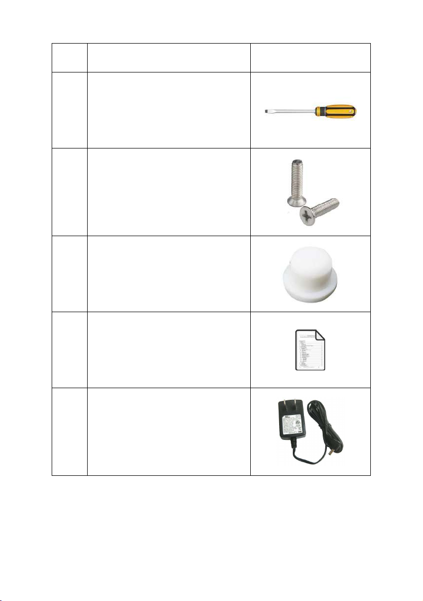
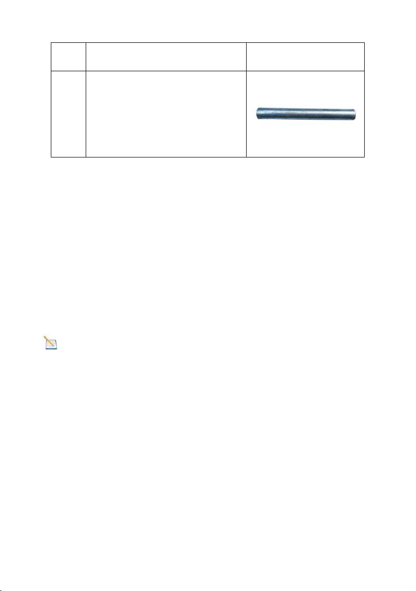
3.1 Parts List.........................................................................3
3.2 Recommend Tools.........................................................7
3.3 Sensor Assembly Set Up................................................7
3.3.1 Install Integrated Outdoor Sensor Battery................8
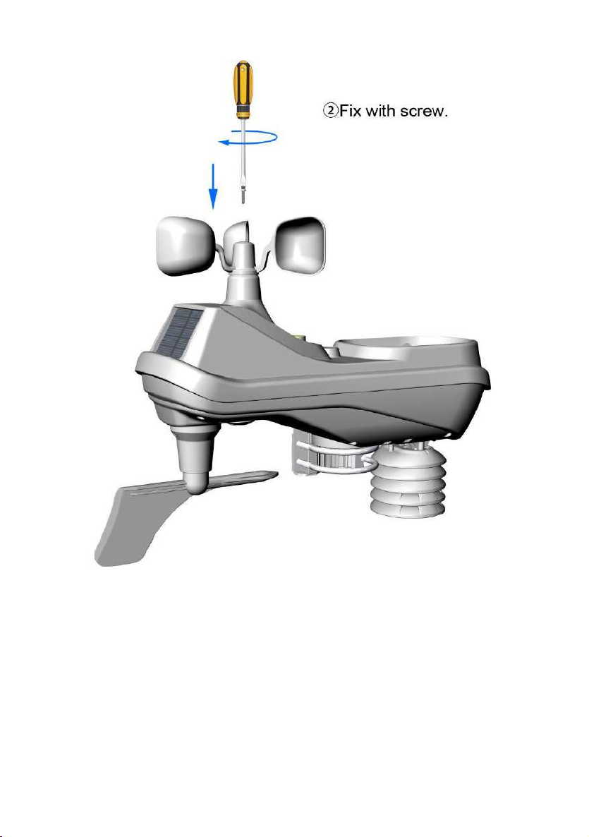
3.3.2 Wind Cup Installation.............................................10
3.3.3 Rain Gauge Installation..........................................12
3.3.4 Battery Installation ................................................13
3.3.5 Reset Integrated Outdoor Sensor .........................15
3.4 Display Console................................................16
3.4.1 Layout of Display Console.....................................16
3.4.2 Setup the Display Console ....................................17
3.4.3 Connect Sensors with Display Console.................18
3.5 Sensor Operation Verification.......................................19
3.6 WiFi Setup Guide.........................................................20
4. Sensors Pre-Installation.....................................................20
4.1 Test the Sensors Before Installation.............................20
4.2 Site Survey Before Installation......................................21
4.3 Best Practices for Wireless Communication.................21
5. Final Installation of Sensors...............................................23
5.1 Integrated outdoor Sensor Installation..........................23
6. Low Battery Icon................................................................28
7. Display Console Operation................................................28
7.1 Quick Display Mode......................................................28

- 2 -
7.2 Set (Program) Mode....................................................29
7.3 Sensor Search Mode................................................32
7.4 Max/Min Viewing and Reset Mode...............................32
7.5 Snooze Mode...............................................................34
7.6 Backlight Mode.............................................................34
8. Alarm Mode........................................................................35
8.1 Alarm Triggered............................................................35
8.2 View High/Low Alarm Value.........................................35
8.3 Setting the Alarms........................................................36
8.4 Alarm and Key Beeper ON/OFF...................................38
9. Optional Calibration Mode............................................38
9.1 Calibration of Temperature Mode.................................39
9.2 Calibration of Humidity Mode........................................40
9.3 Calibration of Sensors Mode........................................40
10. Other Features of Display Console..................................45
10.1 Weather Forecasting..................................................45
10.2 Weather Icons............................................................46
10.3 Moon Phase...............................................................47
10.4 Feels Like Temperature .............................................47
10.5 Pressure Threshold Setting........................................49
10.6 Restore Factory Default..............................................49
11. Maintenance....................................................................49
12. Trouble Shooting Guide...................................................53
13. Specification....................................................................56

- 3 -
1.Introduction
Thank you for your purchase of the FT0365 Professional WIFI
Wireless Weather Station. The following user guide provides
step by step instructions for installation, operation and
troubleshooting.
2.Warnings and Cautions
Warning: Any metal object may attract a lightning strike,
including your weather station mounting pole. Never install the
weather station in a storm.
Warning: Installing your weather station in a high location
may result in injury or death. Perform as much of the initial
check out and operation on the ground and inside a building or
home. Only install the weather station on a clear, dry day.
3.Getting Started
The FT0365 weather station consists of a display console, a
sensor array with Integrated Outdoor Sensor, and mounting
hardware.
3.1 Parts List
The weather station consists of the following parts (as
referenced in Figure 1 ).

- 4 -
QTY
Item
Image
1
Display Console
Frame Dimensions :
6.5X 5.32X 0.71inch
(165×135×18mm)
LCD Dimensions:
5.12 x 3.16inch(130×80mm)
1
(7-in-1) Design
Integrated Outdoor
Transmitter
Dimensions (LxHxW):
330x120x270mm
1
Wind speed
Dimensions:
146 x 146 x 46mm
(Optional)
1
Filter screen
Dimensions:
88 x 59 x 45mm

- 5 -
QTY
Item
Image
4
Washer(Metal gasket)
4
Pole Mounting U-bolt Nuts
(M5)
2
U-Bolt (M5)
Dimensions: 2.4x2.4x0.2inch
(60x60x5mm)
1
L-shaped Stainless Steel
base
Dimensions: 3x1.6x0.6inch
(75x40x15mm)
1
Wrench (M5)
Dimensions: 2.6x0.8x0.08inch
(65x20x2mm)

- 6 -
QTY
Item
Image
1
Screwdriver (M3)
Dimensions: 0.4x3.5inch
(Φ10x90mm)
2
Wind Vane and wind Cup
mounting screws (Ø3)
Dimensions:
M2*6mm(0.23inch)
One is a spare part.
2
Wind Cup Waterproof rubber
plug
Dimensions: 0.16x0.12inch
(Φ4 x 3mm)
1
Manual
1
Power Adapter

- 7 -
QTY
Item
Image
1
Stainless Steel Mounting
Pole
Dimensions: Φ40 x 270mm
(Optional)
Figure 1
3.2 Recommend Tools
Precision screwdriver (for small Phillips screws)
Compass or GPS (for wind direction calibration)
Adjustable Wrench.
3.3 Sensor Assembly Set Up
Note: The outdoor sensor array must be powered and
updating before powering up the console, or the console will
stop scanning and connecting with the sensors.
The following illustration shows the full segment for
Thermo-Hygrometer,WIND,RAIN and UV INDEX sensor.
purposes only ,as shown in Figure 2.

- 8 -
Figure 2
3.3.1 Install wind speed
Push the wind speed into the shaft. as shown in Figure 3.
Tighten the set screw with as shown in Figure 4.
Insert white waterproof rubber at the top of the wind speed
Make sure the wind speed can spin freely.

- 9 -
Figure 3

- 10 -
Figure 4

- 11 -
Figure 5
3.3.2 Install Rain Gauge Debris Filter
Pre- installed to prevent debris from entering the rain gauge. As show
below photo.

- 12 -
Figure 6
3.3.3 Insert batteries into the transmitter.
Locate the battery cover on the transmitter, push and open the
battery compartment, as show in Figure 8.

- 13 -
Figure 8
Remove the battery cover on the back of the sensor , as
shown in Figure 9.

- 14 -
Figure 9
Inserting 3xAA batteries in the battery compartment, as show
in Figure 10.

- 15 -
Figure 10
Close the battery cover.
Note: Do not install the batteries backwards. You can
permanently damage the sensors. The solar panel does not
charge the batteries, so rechargeable batteries are not needed
or recommended.

- 16 -
Note: We recommend installing Lithium AA batteries for
sensors.
The sensor LED indicator will light for 3 seconds, and then
flash once per 16 seconds thereafter. Each time it flashes, the
sensor is transmitting data.
Place the battery cover and push it to close the compartment.
Note: If the sensor does not power up after inserting
the batteries, press the reset button shown in Figure 11.
Figure 11

- 17 -
3.4 Display Console
3.4.1 Layout of Display Console
The following illustration shows display console features in
normal mode as below :

- 18 -
1.Outdoor temp HI/LO alarm icon
2.Outdoor low battery indicator
3.Outdoor humidity display
4.Sunshine intensity
5.UV Index display
6.Rainfall display(1H,24h,WEEK,MONTH,
TOTAL)
7.Wind gust display
8.Time
9.Wind average display
10.Weeks and Seconds
11.Date or Year
12.Moon Phase icon
13.Pressure (REL and ABS)
14.Weather forecast icon
15.Humidity rate of change
16.Temperature units (°F or °C)
17.Indoor temperature display
18.WiFi network signal icon
19.Wind direction icon
20.Outdoor temperature display
3.4.2 Setup the Display Console
1. Plug in the display console with power adapter. BL ON
will display in the time area for three seconds when powered
up.
Note: It is recommended to plug in the power adapter to
reduce the battery consumption and extend the service life.
2. Display Console Batteries Installation
Remove the battery door on the back of the display, as shown
in Figure 4. Install three AAA (alkaline or lithium) batteries. The

- 19 -
display will beep once and layout of display will light up for a
few seconds to verify all segments are operating properly.
Figure 4
Recover the battery door, and unfold out the desk stand to
place the console in the upright position
Note: The battery is a back-up of weather station console,
saving console settings when powered off from adaptor.
3.4.3 Connect Sensors with Display Console
Once the display console is powered up, it will automatically
scan all the nearby Integrated Outdoor sensors.

- 20 -
Note: Do not press any button until all the remote sensors
report in the display screen, otherwise the display console will
terminate to connect with remote sensors.
Note: While in the search mode, the remote search icon
will be constantly displayed until all the measured values
received. The console will automatically switch to the normal
mode from which all further settings can be performed.
When connected with the Integrated Outdoor Sensor, the
measured value (Outdoor temperature, humidity, wind speed,
wind direction, wind gust and average, rainfall, UV and
Sunlight index, Dew point and feels like) will show up on the
display console.
Note: Make sure that the distance between weather station
sensors and display console should be within 10ft (3m) to 100ft
(30m). If the weather station sensors is too close or too far
away, it may not receive a proper signal.
3.5 Sensor Operation Verification
The following steps verify proper operation of the sensors prior
to installing the sensor array.
1. Verify proper operation of the rain gauge. Tip the
Integrated outdoor sensor back and forth several times. You
will heard a “ticking” sound within the rain gauge. Verify the
rain reading on the display console is not reading 0.00. Each
“ticking” represents 0.01 inch of rainfall.
Table of contents
Popular Weather Station manuals by other brands

Siemens
Siemens WS1 Operating and mounting instructions

Kemot
Kemot URZ3216 owner's manual

WeatherHawk
WeatherHawk 600 Series quick start guide

TZS First AUSTRIA
TZS First AUSTRIA FA-2460-3-BA instruction manual

La Crosse Technology
La Crosse Technology WS-2810U Operation manual

La Crosse Technology
La Crosse Technology WS-9055TWC instruction manual