Ugin e.on sinter base User manual

INSTRUCTIONS FOR USE
Sintering furnace
Rév. 251121

Instructions for use (rev 251121)
e.ON sinter base
UGIN DENTAIRE 1
e.ON sinter base
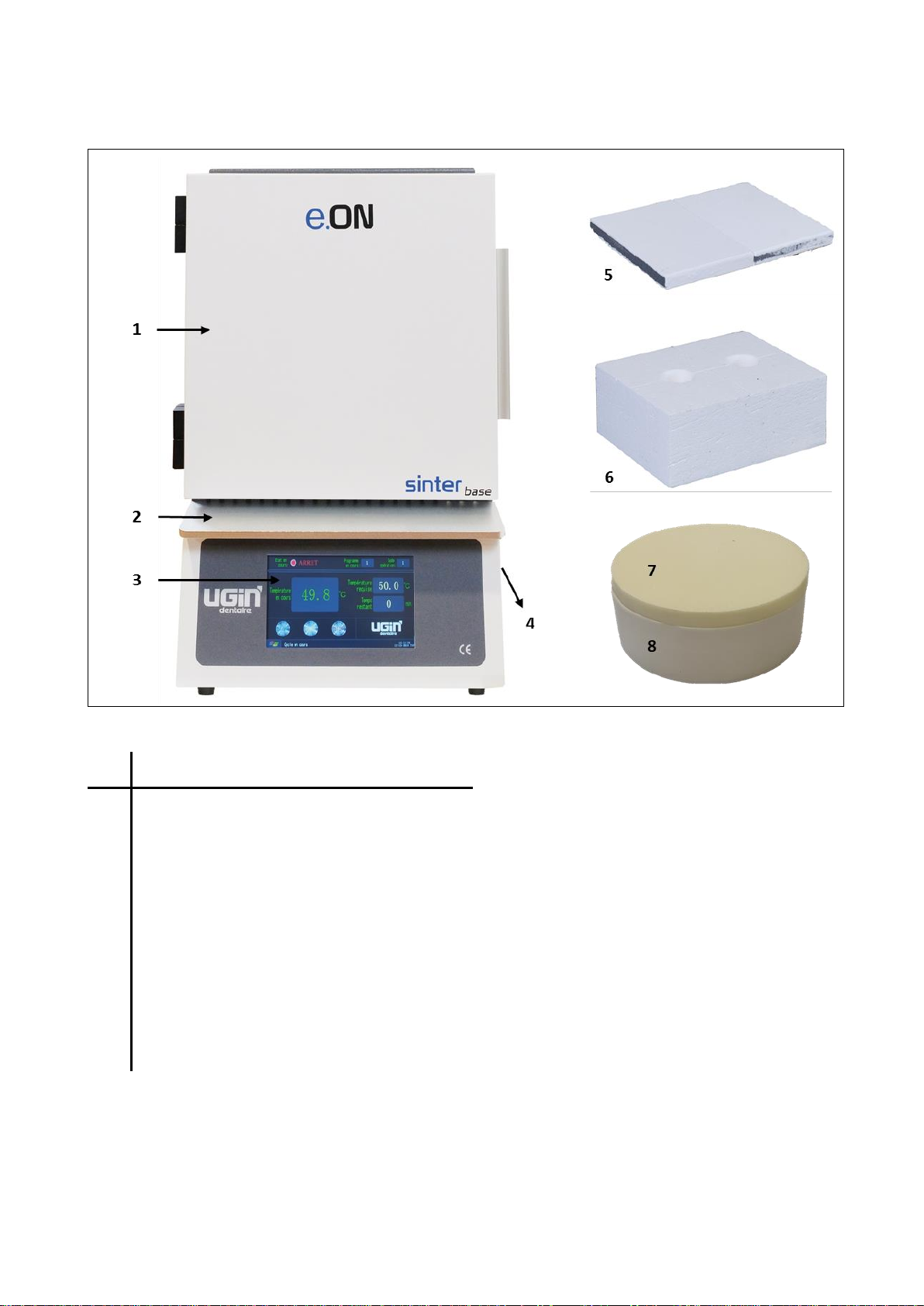
A. EQUIPEMENT DESCRIPTION .................................................................................................................2
B. WIRING DIAGRAM ................................................................................................................................3
C. INSTRUCTIONS FOR USE .......................................................................................................................4
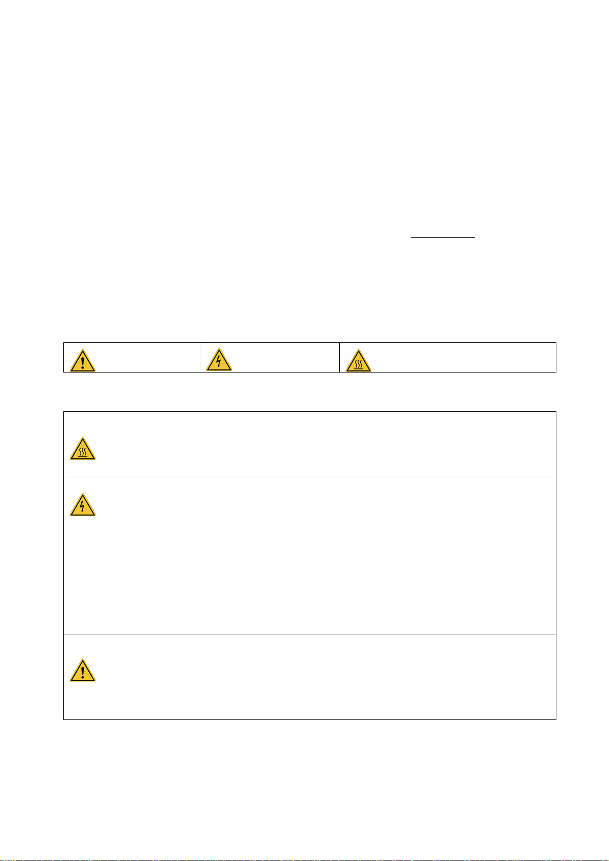
1. SAFETY INSTRUCTIONS ........................................................................................................................4
1.1. USE .................................................................................................................................................4
1.2. SAFETY INSTRUCTIONS ...................................................................................................................4
1.3. WASTE DISPOSAL............................................................................................................................6
2. EC DECLARATION OF CONFORMITY.....................................................................................................6
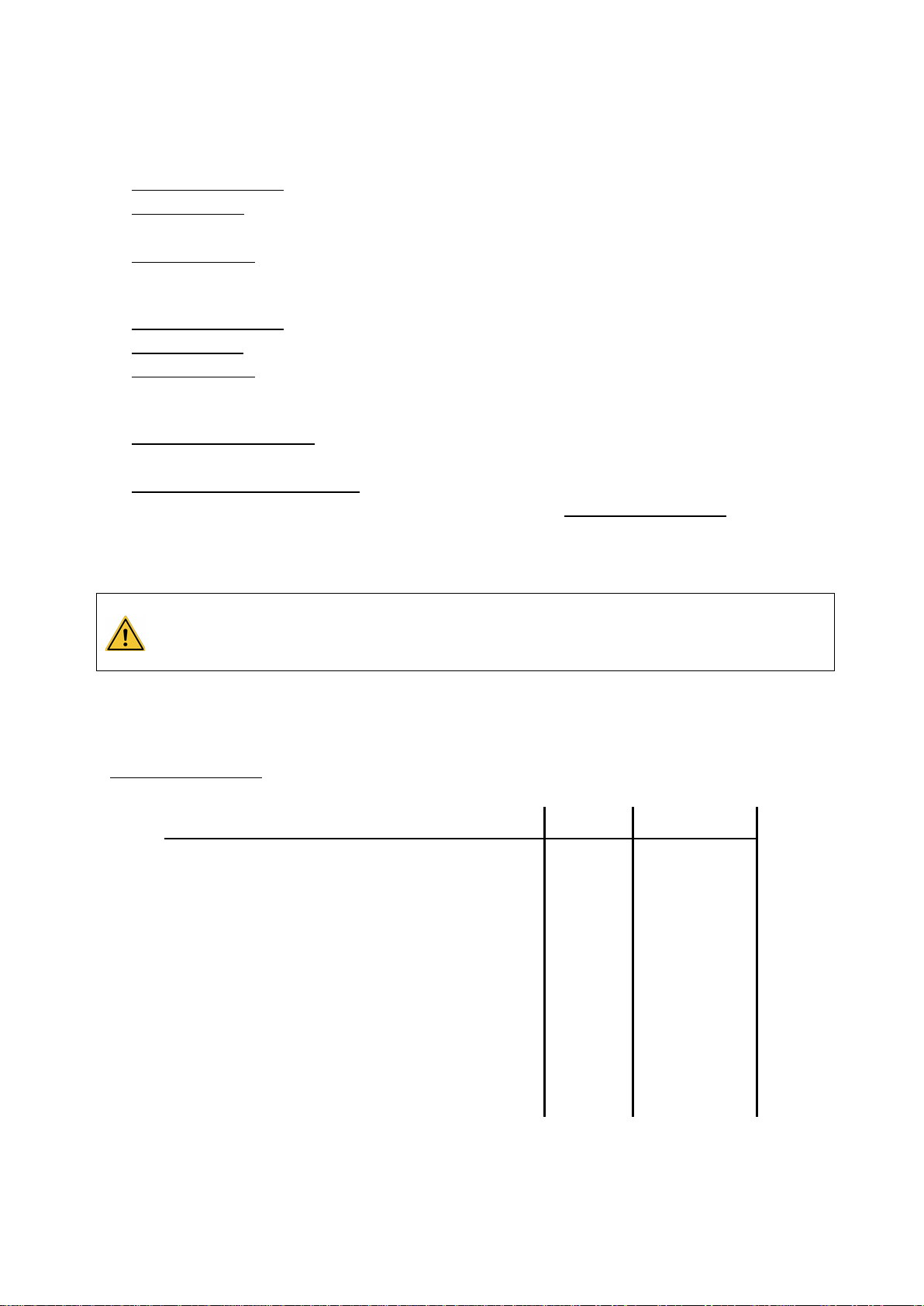
3. TECHNICAL INFORMATION ..................................................................................................................7
3.1. TECHNICAL DATA............................................................................................................................7
3.2. CONDITIONS OF USE, TRANSPORT AND STORAGE .........................................................................8
3.3. ACCESSORIES ..................................................................................................................................8
4. INSTALLATION......................................................................................................................................9
4.1. UNPACK ..........................................................................................................................................9
4.2. INSTALLATION ................................................................................................................................9
4.3. BEFORE START-UP ..........................................................................................................................9
5. START-UP...........................................................................................................................................10
6. USE AND CONFIGURATION................................................................................................................11
6.1. WORKING INTERFACE...................................................................................................................11
6.2. CONTROL KEYS..............................................................................................................................11
6.3. REAL-TIME CURVE (CURRENT CYCLE) ...........................................................................................11
6.4. INTERFACE PROGRAM EDITOR .....................................................................................................12
6.4.1. CHANGE SETTINGS........................................................................................................................12
6.4.2. PROGRAMMING INSTRUCTIONS...................................................................................................13
6.4.2.1. EXAMPLES OF CALCULATION ................................................................................................14
6.5. PARAMETER SETTING ...................................................................................................................14
6.6. PROGRAMS...................................................................................................................................15
6.6.1. PROGRAM PRE-RECORDERED No. 1 .............................................................................................15
6.6.2. PROGRAM PRE-RECORDERED No. 40 –DECONTAMINATION PROGRAM.....................................15
6.7. POSITIONING THE ELEMENTS AND STARTING THE CYCLE ............................................................16
6.7.1. POSITIONING OF ELEMENTS AND TRAY FOR SINTERIZING ...........................................................16
6.7.2. CLOSING THE CHAMBER...............................................................................................................17
6.7.3. CLOSING THE PLATFORM AND START CYCLE ................................................................................17
7. ADVICES - PRECAUTIONS FOR USE.....................................................................................................18
8. MAINTENANCE ..................................................................................................................................20
8.1. HEATING ELEMENT REPLACEMENT ..............................................................................................21
8.2. TROUBLE-SHOOTING ....................................................................................................................22
Non-contractual visual
Translation into English from original in French

Instructions for use (rev 251121)
e.ON sinter base
UGIN DENTAIRE 2
A. EQUIPEMENT DESCRIPTION
N°
DESCRIPTION
1
Door of the chamber
2
Magnetic tablet
3
Touch screen
4
Power switch ON/OFF (lateral side)
5
Sole (2 units)
6
Insulating plate
7
Tray for sinterizing cover
8
Tray for sinterizing

Instructions for use (rev 251121)
e.ON sinter base
UGIN DENTAIRE 3
B. WIRING DIAGRAM

Instructions for use (rev 251121)
e.ON sinter base
UGIN DENTAIRE 4
C. INSTRUCTIONS FOR USE
1. SAFETY INSTRUCTIONS
1.1. USE
e.ON sinter base is a sintering furnace to Zirconium oxide (ZrO2) dental prostheses. This furnace has to be
operated only by dental professionals. e.ON sinter base have to use in the conditions and for the uses
described in this manual. Any other use that will be made of it is considered inappropriate. In this case, the
manufacturer declines all liability and immediately cancels the equipment warranty.
According to the product’s instructions and functionalities, it is imperative to read carefully the instructions
for use before furnace installation and use. Retain the manual for future reference.
1.2. SAFETY INSTRUCTIONS
Pictograms’ meaning used in these instructions for use:
General warning
Electrical hazard
Burn hazard - Hot surface
Observe following safety instructions:
-During operation and after use, the furnace surface, sole, insulating plate, tray for sinterizing
and cover may reach high temperatures: do not touch.
-Wear suitable gloves for handling prosthetic objects, tray for sinterizing/cover, sole and
insulating plate.
-The unit must be connected to an electrical installation in accordance with the applicable
standard in the country in which it is being used. This installation must provide protection
against overcurrent, overload and ground faults.
-This furnace requires its own power line and must be connected to a circuit breaker.
-Connect it directly to the mains socket. Do not use multiple sockets.
-Ensure that the connection cables are in perfect condition to prevent short circuits.
-Before any technical intervention, the unit must be switched off (with the breaker) and
disconnected from the mains power supply.
-Do not spill liquid on the ventilation openings or inside the furnace.
-Do not place any object inside the chamber (only tray for sinterizing/cover, sole and insulating
plate).
-The furnace must be placed on a flat surface, keeping sufficient clearance around the unit to
ensure proper ventilation.
-Do not block the ventilation openings to avoid overheating.

Instructions for use (rev 251121)
e.ON sinter base
UGIN DENTAIRE 5
-For moving:
-take hold the furnace by its base: NEVER LIFT BY UPPER PART OF FURNACE
-the furnace must remain in an upright position: NOT HORIZONTAL POSITION
-Never use the furnace without sole and insulating plate.
-Use only the sole, insulating plate, tray for sinterizing and cover provided by UGIN DENTAIRE.
Before use, check it (no dirt or damage). If damage: do not use.
-Respect the positioning of elements (see chapter 6.7): damage equipment risk.
-The chamber is made up refractory ceramic fibres.
-Handle carefully.
-They can release dust: remove with a vacuum cleaner - do not blow or use compressed air.
-Use only genuine spare parts. The use of non-original spare parts voids any warranty for your
device.
-Do not introduce stranger objects inside the unit during the maintenance operations. It is
forbidden to modify the material without authorization.
-Do not execute different operations of maintenance from those brought back in the manual.
Whichever operation not included in this manual, can involve risks.
-For whichever information concerning installation, maintenance and use, contact the
customer’s service UGIN DENTAIRE.

Instructions for use (rev 251121)
e.ON sinter base
UGIN DENTAIRE 6
1.3. WASTE DISPOSAL
Observe the waste disposal regulations for electrical and electronic equipment: do not dispose of with
household waste.
The unit is subject to Directive 2012/19/EU on waste electrical and electronic equipment and to the laws of
the country in which it is being used, and must be disposed of in accordance with applicable regulations.
The chamber contains refractory ceramic fibres. They must be disposed in accordance with applicable
regulations in force.
2. EC DECLARATION OF CONFORMITY
The equipment’s EC declaration of conformity is provided as appendix of instructions for use.
Content of the declaration EC:
▪Name and address of the manufacturer:
UGIN DENTAIRE
25 rue de la Tuilerie
38170 SEYSSINET-PARISET –FRANCE
▪UGIN DENTAIRE declares, on its own exclusive responsibility, that the product:
- Sintering furnace e.ON sinter base
- Serial number: see the equipment’s EC declaration of conformity
▪Fulfills the essential requirements of health and safety of the following directives:
- Machinery directive 2006/42/EC
- Electromagnetic compatibility directive 2014/30/EU

Instructions for use (rev 251121)
e.ON sinter base
UGIN DENTAIRE 7
3. TECHNICAL INFORMATION
3.1. TECHNICAL DATA
e.ON sinter base is a sintering furnace to Zirconium oxide dental prostheses. This furnace must be operated
only by dental professionals and in the conditions described in this manual (see chapter 1.1 and 3.2).
TECHNICAL DATA
Maximum temperature
1 600°C
Temperature accuracy
± 1°C
Heating rate
To 40°C/minute maximum
Screen
High definition colour touch screen 7’’ (155x87mm)
Number of programs
40 free programs (with 40 possible stages)
Number of heating elements (rods)
4 in MoSi2(molybdenum disilicide)
Sensor
Sensor double components Pt/Rh (Platinum / Rhodium)
Dimensions
(height, width, depth)
540mm x 400mm x 450mm
Weight
58 kg
Chamber size
110 mm x 110 mm x 110 mm
Maximum power consumption
1 830 W
Supply voltage
230 V (50/60 Hz)

Instructions for use (rev 251121)
e.ON sinter base
UGIN DENTAIRE 8
3.2. CONDITIONS OF USE, TRANSPORT AND STORAGE
▪Authorised conditions of use
-Ambient temperature: +10°C to +40°C.
-Humidity range: maximum relative humidity 80% for temperatures until 31°C, without condensation
and decrease linear until 50% to 40°C, without condensation.
-Ambient pressure: up to an altitude of 2000 m above sea level.
▪Authorised conditions of storage
-Ambient temperature: -20°C to +65°C.
-Humidity range: maximum relative humidity 80%.
-Ambient pressure: up to an altitude of 2000 m above sea level.
▪Conditions to transport
-Wait the complete cooling before packing/transporting.
-Use the original packaging only, with the protective elements (polystyrene...).
-Take hold the furnace by its base, never lift by upper part of furnace.
-For transport, the furnace must remain in an upright position: not horizontal position.
-Install the furnace in the packaging with the protective elements. Also protect the accessories for
transportation.
NEVER LIFT BY UPPER PART OF FURNACE: risk material damage.
For transport, the furnace must remain in an upright position: NOT HORIZONTAL POSITION.
Heating elements may be damaged in horizontal position due to vibration/shock.
3.3. ACCESSORIES
▪Accessories delivered with the furnace (included in the packaging):
ACCESSORIES
QUANTITY
UGIN CODE
-Tray for sinterizing
1
FCE07SIN0030
-Tray for sinterizing cover
1
FCE07SIN0023
-Box of zirconia pearls
1
FCE03SIN0001
-Sole
2
FCE07THE0005
-Insulating plate
2
FCE07THE0003
-Magnetic tablet
1
---
-Wrench (for tighten the heating elements)
1
---
-Allen wrench (number 3 and 4)
2
---
-Fuse 32A
2
---

Instructions for use (rev 251121)
e.ON sinter base
UGIN DENTAIRE 9
4. INSTALLATION
4.1. UNPACK
-Unpack e.ON sinter base and check that it is in perfect order (furnace and accessories).
-Any defects can be reported to the carrier.
-Remember to get the carrier to sign the delivery note.
NOTE: keep the original packaging to transport the furnace (see chapter 3.2)
4.2. INSTALLATION
-Install in a room aired. Observe the conditions indicated in chapter 3.2.
-Place the furnace on a level and aired surface. Keep a distance from other objects around not less than
25 cm. Keep it away from heat sources (radiators and/or other equipment that release heat).
-Despite excellent insulation, the furnace provides heat and, in the long term, can discolour surfaces that
are nearest.
-Do not shake the furnace, avoid vibrations and shock.
-The molybdenum silicon rods are very brittle at room temperature: DO NOT HANDLE THEM. Avoid moving
the furnace after installation.
-Dust, corrosive or explosive gases can damage the body and the insulation.
-Its forbidden placing inflammables, toxic, volatile or explosives around the furnace.
This unit requires its own power line and must be connected to a circuit breaker.
Grounding is mandatory to avoid accidents and the dangers of overheating the power line.
Due to the power of furnace: connect it directly to the mains, do not use multiple sockets (risk of
electrical interference).
4.3. BEFORE START-UP
-Open the furnace upper cover (unscrew).
-Carefully remove the cushioning foam pad protecting heating elements.
-Then visually inspect the heating element (no damage). Avoid handling.
-Close the furnace cover (screw).

Instructions for use (rev 251121)
e.ON sinter base
UGIN DENTAIRE 10
5. START-UP
After checking that the mains voltage matches that noted on the rating plate, plug the cord into a standard
20A socket with a ground terminal.
NOTE: If not used for a long time, switch off the power supply.
a) Activate the breaker (ON/OFF) of furnace.
b) Following power up, the initialization interface appears
on the screen. The main screen automatically appears
as follows: menu “Working interface”.
c) Open the door of the heating chamber.
Remove the protections and dust with a vacuum cleaner or a soft and clean brush (do not use
compressed air).
DO NOT PLACE ANY OBJECT INSIDE THE CHAMBER
(only tray for sinterizing and cover, sole and insulating plate)
IMPORTANT
▪For the first time or after a long time without use, need to preheat the muffle furnace 1 hour
at 120°C follow 2 hours at 300°C to eliminate condensation and avoid fractures of the refractory
material.
▪Carry out a decontamination program as a precautionary measure before the first use of the
furnace: start the pre-recorded program number 40 (see chapter 5.6.1).

Instructions for use (rev 251121)
e.ON sinter base
UGIN DENTAIRE 11
6. USE AND CONFIGURATION
6.1. WORKING INTERFACE
Following power up, the initialization interface appears on the screen.
The main screen automatically appears: menu “Working interface”.
6.2. CONTROL KEYS
PICTURES
KEYS
DESCRIPTION
Start cycle
(RUN)
The selected program is started.
Pause
(PAUSE)
In running state, the program will be in a suspended state, the
temperature remains constant.
Stop
(STOP)
Under operating state or suspended state, the program will end.
Menu
(logo Microsoft)
Pull-down menu appears, as shown below:
Working interface
Parameters current cycle display.
Real-time curve
Display of the cycle curve (temperature/time).
Program editor
Program settings.
Parameter setting
Software settings. Only access with technician code (reserved for
technicians customer’s service UGIN DENTAIRE).
Language selection
Available languages: English, French, Spanish and Italian.
Date setting
Setting the date, time and day of the week.
6.3. REAL-TIME CURVE (CURRENT CYCLE)
This screen shows the diagram of the current cycle
(time/temperature).
On the screen are displayed two curves: the temperature
setting in the cycle (blue curve) and the temperature in real
time (green curve).
The green curve appears with the blue curve superimposed
with the temperature is regulated.

Instructions for use (rev 251121)
e.ON sinter base
UGIN DENTAIRE 12
6.4. INTERFACE PROGRAM EDITOR
A total of 40 programs, composed of 40 temperature/time
pairs, can be edited and saved by selecting a different
program number, each program and pairs of can be edited.
To select a program, press the right or left arrow key: the
numbers of programs is displayed on the screen.
For each program number, the cycle parameters are
displayed as a chart:
-C represents temperature (°C), and
-T represents time (minutes).
Each program is two pages: the first page displays the pairs from C01/T01 to C20/T20 and the second page
from C21/T21 to C40/T40. The “NEXT PAGE”key switches from the first page to the second page.
6.4.1. CHANGE SETTINGS
When the program number is displayed on the screen,
“press” the parameter to be modified. A numeric keypad is
displayed to select the desired value.
Enter the new value using the numeric keypad and press
“Ok”to save.
A confirmation message is displayed:
“Caution: press the Ok key, the data will be saved”.
Press “Ok”to confirm or “Cancel”to cancel.
When the desired changes of program have been made, press “SAVE”key to save the complete program.
After validation, the “Working interface” displayed on the screen.

Instructions for use (rev 251121)
e.ON sinter base
UGIN DENTAIRE 13
6.4.2. PROGRAMMING INSTRUCTIONS
C: Temperature in degrees Celsius (°C)
T: Time in minutes (min)
Temperature 1
Used as the temperature start value (usually set to 50).
Time 1
Total duration of first stage (0 to 9999 minutes).
Temperature 2
Final temperature of first stage and start temperature of second stage.
Temperature values from C1 to C2 define the increase rate.
The value must be less than 10°C/min, when below 300°C.
Time 2
Total duration of second stage (0 to 9999 minutes).
Temperature 3
Final temperature of second stage and start temperature of third stage.
If C3 is less than C2 (temperature decrease). The value must be less than 30°C/min.
Time 3
Total duration of third stage (0 to 9999 minutes).
Temperature 4
Final temperature of third stage and start temperature of fourth stage.
If necessary, the parameters are programmed as for the previous steps.
Last time « -
121 »
Indicates the end of program, temperature controller works according to the
temperature/time parameters setting.
When the program detects a “-121”, STOP command is activated with return to the
previously selected program.
“-121”also indicates correct cycle sequence.
ATTENTION: The operator must setting the temperature/time initial and the temperature/time final for
each stage. These data must be calculated from the desired increase/decrease rate, following the
recommendations given (see examples below). Never write on the screen the desired speed directly, the
software cannot make the calculation and it takes the value as a temperature or a time “untreated”.
ATTENTION: end program with “-121” time, otherwise cycle will not stop.

Instructions for use (rev 251121)
e.ON sinter base
UGIN DENTAIRE 14
6.4.2.1. EXAMPLES OF CALCULATION
▪Calculation time of second stage (T02)
From the initial and final temperature values of the second stage, calculation of the time stage:
Temperature 1 →C01 = 900°C
Temperature 2 →C02 = 1200°C
Temperature difference:
C02 –C01 = 1200°C –900°C = 300°C
Recommended value of increase rate: less than 10°C/minute
300°C at a rate of 10°C/min →300°C / 10°C = 30 min →T02 = 30 minutes
▪Parameters for remain to end temperature (T04)
Parameters temperature/time of end stage to obtain remains to the end temperature of 1520°C for 2 hours:
Temperature 4 →C04 = 1250°C
Temperature 5 →C05 = 1250°C
Temperature difference = 0°C:
Temperature remains to 1250°C
Time remains: 2 hours
Time 04: 2 hours x 60 min = 120 min
→T04 = 120 minutes
Zirconia SINTERING TEMPERATURES are given as indicative by disc manufacturer. If necessary,
these one can be adjusted from -15°C to +15°C around the final temperature recommended.
We recommend adjusting the temperature/time for special work.
6.5. PARAMETER SETTING
This interface requires a password to be accessible.
No data may be modified without authorization: risk of
damages on the furnace or trigger heating untimely.
The modification of the parameters is therefore reserved
for technicians of customer’s service UGIN DENTAIRE.
NOTE: even if changes are made to the settings, when saving them, a screen is displayed to insert the
password. When no password has been inserted and validation is done with the “Ok”key, the changes made
are not saved and the original settings remain applicable.

Instructions for use (rev 251121)
e.ON sinter base
UGIN DENTAIRE 15
6.6. PROGRAMS
Two programs are pre-recorded in the furnace:
6.6.1. PROGRAM PRE-RECORDERED No. 1
C01
50,0
C06
1200,0
C11
0,0
C16
0,0
T01
25
T06
25
T11
0
T16
0
C02
300,0
C07
1450,0
C12
0,0
C17
0,0
T02
40
T07
30
T12
0
T17
0
C03
600,0
C08
1450,0
C13
0,0
C18
0,0
T03
40
T08
30
T13
0
T18
0
C04
1000,0
C09
1200,0
C14
0,0
C19
0,0
T04
20
T09
30
T14
0
T19
0
C05
1200,0
C10
1200,0
C15
0,0
C20
0,0
T05
10
T10
-121
T15
0
T20
0
6.6.2. PROGRAM PRE-RECORDERED No. 40 –DECONTAMINATION PROGRAM
C01
50,0
C06
900,0
C11
0,0
C16
0,0
T01
40
T06
-121
T11
0
T16
0
C02
300,0
C07
0,0
C12
0,0
C17
0,0
T02
70
T07
0
T12
0
T17
0
C03
1000,0
C08
0,0
C13
0,0
C18
0,0
T03
150
T08
0
T13
0
T18
0
C04
1590,0
C09
0,0
C14
0,0
C19
0,0
T04
60
T09
0
T14
0
T19
0
C05
1590,0
C10
0,0
C15
0,0
C20
0,0
T05
70
T10
0
T15
0
T20
0
A DECONTAMINATION PROGRAM MUST BE CARRIED OUT AS A PRECAUTIONARY MEASURE
BEFORE THE FIRST USE OF THE FURNACE: start the pre-recorded program number 40.
If use different types of zirconia, zirconia of different brands or zirconia with different sintering temperatures
(even during separate sintering cycles) it may be necessary to carry out regular decontamination of the
furnace e.ON sinter base using the cycle recorded in number 40.
Decontamination before the 10th cycle following the previous one is highly recommended.
PRECAUTIONS:
▪High translucency zirconia are very sensitives. To avoid and prevent crossed discoloration with other
zirconia brand or type, user must do regularly decontamination program.
▪If liquid shades are used with staining technic, prosthetics units must be dry and preheated with an infra
red lamp or into an oven to prevent pollution into the eON sinter base, in following zirconia and shades
manufacturer recommendations.

Instructions for use (rev 251121)
e.ON sinter base
UGIN DENTAIRE 16
▪White clusters can appear on the rods (heating elements) when different brands or types of zirconia are
used. In this case user must clean muffle and rods with a special zirconia cleaner like Nacera Clean
(registered brand) with decontamination program No. 40.
▪Always place the sole (2 units) and insulating plate in the chamber during carry out a decontamination
cycle.
ADVICE: add in a tray with or without a cover white Zirconia smashed in multiple small pieces (absorption of
pollutants) or a powder specially designed to improve the effectiveness of decontamination. After running
the program, check the condition of the rods:
- still whitish traces = still contaminated: repeat a decontamination cycle;
- rods with a grey shiny appearance = ok: furnace ready.
6.7. POSITIONING THE ELEMENTS AND STARTING THE CYCLE
IMPORTANT!
Before use, check if it is in perfect condition the tray, cover, sole and insulating plate: presence of dirt or
damage.
-Clean with brush if necessary (see chapter 8 - Maintenance)
-If the component is damaged or cracked, do not use and replace it.
Use only the original tray, cover, sole and insulating plate e.ON SINTER UGIN DENTAIRE
6.7.1. POSITIONING OF ELEMENTS AND TRAY FOR SINTERIZING
▪Empty a zirconia pearls into a tray (a layer at the bottom to prevent the elements from rubbing on the
bottom and sides).
▪Place the elements in a tray (avoid touch amongst themselves).
▪Always place the cover on the tray.
-Capacity till 20 units.
-Beads for sinterizing must be changed in any tray if a discoloration in yellow colour appears.

Instructions for use (rev 251121)
e.ON sinter base
UGIN DENTAIRE 17
6.7.2. CLOSING THE CHAMBER
1
2
Check if the heating chamber is in
perfect condition: presence of dirt
or damage, any object.
-Place the sole in the chamber (both units: a & b)
-Place the tray for sinterizing (see chapter 6.7.1)at the
center of chamber (c)
3
4
Place the insulating plate (vertically)
for closing the chamber.
Close the door of the chamber.
Note: the sole can remain at its location for the realization of the following cycles.
At the end of the cycle, wear suitable gloves to remove insulating plate and tray for sinterizing: hot
surfaces - risk of burns.
6.7.3. CLOSING THE PLATFORM AND START CYCLE
When the cycle has been selected and setting (see previous chapters) start the cycle: press “RUN” key.
Note: when start the cycle, the noise generated by the power transformer is normal.

Instructions for use (rev 251121)
e.ON sinter base
UGIN DENTAIRE 18
7. ADVICES - PRECAUTIONS FOR USE
GENERAL
-During operation and after use, the surface of
the furnace head may become very hot: avoid
direct contact with the skin (risk of burns).
-eON sinter base is equipped with heat
extractors to control the temperature of the
components and guarantee safety: do not
cover the furnace during use and do not place
objects on the furnace or on the ventilation
openings.
CYCLE START AND CONFIGURATION
-Do not open the door during high temperature
cycles: danger of burns and risk of irreversible
damage to heating elements and refractories.
-At the end of the cycle, the temperature must
be lower than 300°C before opening the
furnace. Do not switch off the power supply,
because heat extractors are stopped and the
internal temperature increases and can
damage the equipment.
-If the temperature is above 300°C, it is not
possible to start a cycle (risk of damaging the
refractories.) Wait for cooling: temperature
displayed on the screen below 300°C.
-When the temperature is below 200°C, the
power supply can be switched off (switch at
the back of furnace).
-At the end of the cycle, the furnace
automatically returns to the standby position.
-When the furnace is in standby, the door must
be closed to avoid condensation.
-At the start of the cycle, avoid using an
increase rate too fast to avoid damaging the
heating elements. Likewise, a large difference
between two increase rates is not
recommended.
-Observe the recommendations of the
manufacturer of Zirconia to avoid significant
gaseous emissions which may damage the
muffle.
-For the first time or after a long time without
use, need to preheat the muffle furnace 1 hour
at 120°C follow 2 hours at 300°C to eliminate
condensation and avoid fractures of the
refractory material.
-Zirconia sintering temperatures are given as
indicative by disc manufacturer. If necessary,
these one can be adjusted from -15°C to +15°C
around the final temperature recommended.
HEATING ELEMENTS (RODS)
-Molybdenum silicon rods are very brittle at
room temperature: do not handle them.
-The heating elements must not be maintained
for long periods between 400°C and 700°C to
avoid their oxidation.

Instructions for use (rev 251121)
e.ON sinter base
UGIN DENTAIRE 19
ELEMENTS - CHAMBER (see chapter 6.7.1 –6.7.2)
-Place the sole (2 units) and insulating plate
while the furnace is working.
-Observe the information about the positioning
of elements (chapter 6.7).
-Always place the elements in the tray for
sinterizing, with the zirconia beads inside, and
place the cover.
-Beads for sintering must be changed in any tray
if a discoloration in yellow colour appears.
DECONTAMINATION PROGRAM (see chapter 6.6)
-Before first sintering, user must launch a
decontamination program (No. 40).
-Always place the sole (2 units) and the
insulating plate in the chamber during carry
out a decontamination program.
-Add in a tray with or without a cover white
Zirconia smashed in multiple small pieces
(absorption of pollutants) or a powder specially
designed to improve the effectiveness of
decontamination. After running the program,
check the condition of the rods:
-still whitish traces = still contaminated:
repeat a decontamination cycle;
-rods with a grey shiny appearance = ok:
furnace ready.
- High translucency zirconia are very sensitives
(crossed discoloration risk): user must do
regularly decontamination program.
-If liquid shades are used with staining technic,
prosthetics units must be dry and preheated
with an infra-red lamp or into an oven to
prevent pollution into the eON sinter base, in
following zirconia and shades manufacturer
recommendations.
-White clusters can appear on the rods (heating
elements) when different brands or types of
zirconia are used: user must clean chamber and
rods with a special zirconia cleaner like Nacera
Clean (registered brand) with decontamination
program.
Note: observe the instructions set out in chapter 8 –maintenance.
Table of contents
Other Ugin Furnace manuals
Popular Furnace manuals by other brands

Nagas
Nagas DTHC Series Installation and operation manual

Johnson Controls
Johnson Controls EBE23A installation manual

Stelpro
Stelpro SEFL1521 installation guide

Amana
Amana AMH95 Series installation instructions

Lennox
Lennox 90UGF SERIES User's information manual

Carrier
Carrier INFINITY ICS 58MVC Product data

Shelter Furnace
Shelter Furnace SF1000 instruction manual

ECR International
ECR International GTH User's information manual

Carrier
Carrier OBMAAB installation instructions

Walter Wilson
Walter Wilson OLR154F20A Installation instructions and homeowner's manual

ICP
ICP C8MPL User's information manual

Goodman
Goodman GAS-FIRED WARM AIR FURNACE User's information manual