UltraCOOL M201A User manual

Circle the model of your cooler and
record the serial number below.
Read Carefully All Of This Manual
Before Installing The Unit.
Encierre con un circulo el modelo de su
enfriador y escribe el número de serie abajo.
Lea Con Cuidado Todo Este Manual Antes
De Instalar La Unidad.
Serial #
Número De Serie
Read And Save These Instructions
Evaporative Cooling
Evaporative cooling is nature’s way of cooling. When air is moved
over a wet surface, water is evaporated and heat is absorbed. When
stepping out of a swimming pool with the wind blowing, evaporative
cooling makes you feel cool, even though the air may be warm.
The human body itself is cooled primarily by the evaporation of
perspiration.
This unit works on the same principle. Air is drawn across wet
filter pads where the air is cooled by evaporation and then circulated
throughout the building. It is this combination of cooled air and the
movement of air over the skin which makes it feel cool.
Unlike refrigeration systems which recirculate the air, an evaporative
cooler continually brings in fresh air while exhausting old air. You
are completely replacing the air every 2 to 4 minutes by opening
windows or doors or a combination of both. The air is always fresh,
not stale, laden with smoke and odors as happens with refrigerated
air conditioning.
Vea el Español en el interior
110522-1 1-09www.championcooler.com
MOBILE EVAPORATIVE
COOLER
Manual Control Units
M201A
M301A
M401A
Remote Control Units
RM301A
RM401A
Safety Rules
1. Read these instructions carefully.
2. Unit must be in the Off Position and Unplugged from power
receptacle when installing or performing any maintenance.
3. This cooler will run on 120 volt A.C., 60 Hz (cycle) current
only.
4. Motor and pump are grounded and have an automatic thermal
overload switch which will shut motor off if it overheats. The
motor will restart automatically when it cools down.
5. Pump receptacle is for grounded evaporative cooler pump only.
Do not plug anything else into receptacle.
WARNING:Toreducetheriskoffireorelectricshock,donot
use this fan with any “solid-state fan speed control device.”
www.sylvane.com 1-800-934-9194

2110522-1
Cooler Installation
Installing Casters
Note: The installation kit
includes (2) swivel cast-
ers with brake, (2) swivel
casters without brake, (16)
tinnerman nuts and (16)
1/4-20 x 1/2 screws.
• Place the unit on its side.
Place the tinnerman nuts on
thecasterbracketonthebot-
tom pan as shown in figure
1.
• Attach the casters to the
brackets with the screws provided.
Operation
Manual Control Units
• Pump setting. The rotary switch has 6 settings. The “Pump”
setting will operate the pump without the blower. For best results
turn the switch to “Pump” for a few minutes to wet the pads before
operating the fan.
• Highandlowcoolsettings. The “High Cool” and “Low Cool” set-
tings operate both the pump and the blower. Turn the unit to “Low
Cool” when possible. This lower speed allows the air to stay longer
in the wet pads and therefore increases it’s cooling efficiency.
• High and low vent settings. The “High Vent” and “Low Vent”
settings operate the blower without the pump. This is useful on
cool nights or at times when just a fan is desired.
Remote Control Units
These units may be controlled using the 3 buttons on the front panel
of the cooler or with the remote control.
• PUMPbutton. Pressing this button toggles the pump on and off.
When the LED is lit, the pump is running. For best results turn
on the pump for a few minutes to wet the pads before operating
the fan. The pump must be on while operating the fan for cooling.
You may also want the pump turned off at times when just a fan is
desired.
• FAN button. Pressing this button will cycle the fan through High
Speed / Low Speed / Off. The LED’s on the front of the control
indicate wether the fan is on high speed, low speed or off (no LED’s
lit). Note: Therewillbea2seconddelaybetweenabuttonpress
and the operation of the fan.
• ON/OFFbutton. Pressing this button while the pump or fan is on
will turn everything off. Pressing it again while in the off state will
return the fan and pump to their previous operating settings. When
first plugging in the cooler or after power has been interrupted,
pressing the On/Off button will start the cooler in the default state
which is with the pump on and the fan on high.
• Remote Control. To operate the cooler with the remote you must
be within 20 feet and in sight of the cooler. Aim the remote at the
front panel. The buttons on the remote control have the same func-
tions as the buttons on the front panel of the cooler. The remote
uses two AAA alkaline batteries which are included. A holder for
mounting on a wall is also included with the unit.
Connecting Water
• Install drain assembly. Place the
nipple through the hole in the pan,
with the rubber washer between the
pan and the head of the drain nipple
(Fig. 2). Thread nut onto nipple and
draw up tight against bottom of pan.
Thread the drain cap to the nipple and
tighten water tight.
• Install float valve. Refer to figure 3. Install the valve in the pro-
vided hole in the corner post ((R)M301A, (R)M401A) or louvered
side (M201A) using the provided washer and nut. Install the
included garden hose adapter to the float as shown if attaching a
garden hose to the unit. A 1/4 inch water line may also be used to
supply a continuous amount of water to the unit.
• Fill pan with water. You may fill the pan manually for up to 3
hours of cooling. For automatic filling you may attach a garden
hose to the garden hose adapter or a 1/4 inch water line to the float
valve.
Fig. 1
Bottom Pan
Nipple
Rubber Washer
Nut
Drain Cap
Fig. 2
Wiring Diagrams
White-Com.
Black-Hi
Black
Blower
Motor
Pump
Motor
Red-Lo
White-Com.
Green-Ground
Green
Switch
A
B
12
34
Ribbed-Com.
Plain
Green
Exhaust Air
If the unit is used in an enclosed area, open windows or doors to
ensure adequate exhaust. Without an outlet to exhaust the air,
humidity will build up in the enclosed space and the unit will not
cool adequately.
Manual Control Remote Control
Hi
Low
Gnd
Com.
Black
Red
Green
White
Ground
Wire
Blower Motor
Pump
Motor
Blower Panel Control
Ground
Screw
Junction Box
(RM301A)
www.sylvane.com 1-800-934-9194

3
110522-1
replace if necessary. Check the ten-
sion on the belt.A3 lb. force should
deflect the belt 3/4 inches (see Fig.
4). Readjust belt if needed.
• Clean pump. Cleaning the pump
is necessary once a year at start-up.
For your safety, turn unit off and unplug unit and pump. Remove
the pump from the mount slot. Remove the base of the pump (Fig.
5). Clean the pump and turn the impeller to ensure free operation.
Remove the pump spout and check for any blockage. After clean-
ing, reinstall the base onto the
pump. Pressfirmlytomake sure
it is secure. Reattach the pump
to the mount in the cooler using
the plastic retainer toensure that
the pump will not overturn. Do
not forget to replace the spout
and water delivery tube onto the
pump outlet.
Routine Maintenance
• Drain water. It is recommended to drain the water from the
cooler at least once a week. Keeping fresh water in the pan will
help prevent scale and mineral deposits accumulation on the pads.
Always drain all of the water out of the cooler when not in use for
prolonged periods, and particularly at the end of the season.
• Unplug unit from power supply during extended periods of
non-use.
• Cover unit or store inside when not in use.
By following the operating,installation, and maintenance suggestions
as outlined, you can get many years of efficient and satisfactory
service from your cooler. In the event additional information is
desired, your dealer will be more than glad to assist you in every
possible way.
Maintenance
WARNING: Before doing any maintenance be sure power is
off and unit is unplugged. This is for your safety.
Annual Maintenance
• Oil bearings. The blower bearings (M401A & RM401A only)
and cooler motor in this unit should be oiled with a few drops of
non-detergent 20/30 weight oil once each year. The motor does
not need oil if it has no oil lines for oiling. Motors that have no oil
lines are lifetime oiled at the factory and require no further oiling
for the life of the unit.
CAUTION: Do not over oil. Over oiling can cause motor burn
out, due to excessive oil getting into motor winding.
• Change Pads. Pads should be replaced once or twice a season,
depending upon the length of the season. At the beginning and at
mid season a clean pad is more absorbent and efficient and will
deliver substantially more cool air.
• Check belt and belt tension. This applies only to models
(R)M401Awhich are belt driven. Models M201Aand (R)M301A
have direct drive motors. Check the belt for any cracks or wear and
Float Body
Float Rod
Washer
Nut Garden Hose
Adapter
Fig. 3
Note: Do Not Overfill. Fill water to a maximum height of 2 1/2
inches (approximately 1 inch from the top of the bottom pan). If
using a garden hose, the float will need to be adjusted to maintain
this water level. This can be accomplished by bending the float
rod.
Impeller
Remove
Base
Fig. 5
Fig. 4
3 Lb.
3/4 Inches
Limited Warranty
This warranty is extended to the original purchaser of an evaporative cooler installed and used under normal conditions. It does not cover damages in-
curred through accident, neglect, or abuse by the owner. We do not authorize any person or representative to assume for us any other or different liability
in connection with this product.
Terms And Conditions Of The Warranty
For Two Years from date of purchase, we will replace any original component provided by Champion Cooler which fails due to any defect in material or
factory workmanship only.
Exclusions From The Warranty
We are not responsible for replacement of cooler pads. These are disposable components and should be replaced periodically. We are not responsible for
any incidental or consequential damage resulting from any malfunction.
We are not responsible for any damage received from the use of water softeners, chemicals, descale material, plastic wrap, or if a motor of a higher horse-
power than what is shown on the serial plate is used in the unit.
We are not responsible for the cost of service calls to diagnose cause of trouble, or labor charge to repair and/or replace parts.
How To Obtain Service Under This Warranty
Contact the Dealer where you purchased the evaporative cooler. If for any reason you are not satisfied with the response from the dealer, contact the Cus-
tomer Service Department: Champion Cooler, 5800 Murray Street, Little Rock,Arkansas 72209. 1-800-643-8341. [email protected].
This limited warranty applies to the original purchaser only.
Register your product online at www.championcooler.com/eac/onlineregistration-eac.htm
www.sylvane.com 1-800-934-9194

4110522-1
Problem Possible Cause Remedy
Failure to
start or no air
delivery
Inadequate
air delivery
with cooler
running
Inadequate
cooling
1. No electrical power to
unit
• Fuse blown
• Circuit breaker
tripped
• Electric cord un-
plugged or damaged
2. Belt too loose or tight
3. Motor overheated
• Belt too tight
• Blower bearings dry
4. Motor locked
1. Insufficient air exhaust
2. Belt too loose
3. Pads plugged
1. Inadequate exhaust in
house
2. Pads not wet
• Pads plugged
• Open spots in pads
• Trough holes
clogged
• Pump not working
properly
1. Check power
• Replace fuse
• Reset breaker
• Plug in cords or
replace if damaged
2. Adjust belt tension
3. Determine cause of
overheating
• Adjust belt tension
• Oil blower bearings
4. Replace motor
1. Open windows or
doors to increase air
flow
2. Adjust belt tension or
replace if needed
3. Replace pads
1. Open windows or
doors to increase air
flow
2. Check water distribu-
tion system
• Replace pads
• Repack pads
• Clean trough and
unplug holes
• Replace or clean
pump
Troubleshooting
Motor cycles
on and off
Noisy
Excessive
humidity in
house
Musty or
unpleasant
odor
Water drain-
ing from
cooler
1. Low voltage
2. Excessive belt tension
3. Blower shaft tight or
locked
4. Bearings dry
1. Bearings dry
2. Wheel rubbing blower
housing
3. Loose parts
1. Inadequate exhaust
1. Stale or stagnate water
in cooler
2. Pads mildewed or
clogged
3. Pads not wetting
properly
• Trough holes
clogged
• Pump not working
properly
1. Float arm not adjusted
properly
2. Drain assembly leak-
ing
1. Check voltage
2. Adjust belt tension
3. Oil or replace bear-
ings
4. Oil bearings
1. Oil bearings
2. Inspect and realign
3. Tighten loose parts
1. Open doors or win-
dows
1. Drain pan and clean
pads
2. Replace pads
3. Check water distribu-
tion system
• Clean
• Replace or clean
pump
1. Adjust float
2. Tighten nut and drain
cap.
Problem Possible Cause Remedy
Model
Modelo Volts
Voltios Amperage
Ameraje Speed
Velocidad Water Capacity (gal)
Capacidad de Agua (galón)
Weight (lbs.)
Peso (libras)
Dry
Seco Operating
Lleno
M201A 115 4.7 2 4.8 62 102
M301A / RM301A 115 7.9 2 9.2 107 184
M401A / RM401A 115 10.5 2 11.3 169 263
Specifications / Especificaciones
www.sylvane.com 1-800-934-9194

5
110522-1
No. M301A M401A
N° Description / Descripción M201A RM301A RM401A
1. Bottom Pan / Base De La Caja.......................................................................................322902-503 322904-504 322903-508
2. Top Pan / Tapa................................................................................................................110844-1 110844-2 110844-3
3. Blower Support Panel / Panel De Soporte Para El Soplador........................................222908-004 322908-005 322908-006
4. Corner Post, With Float Hole / Poste De Esquina, Con Agujero Para Flotador...........- 224003-022 224003-032
5. Corner Post, For Pump Mount / Poste De Esquina, Para Montar La Bomba ...............- 224003-046 224003-047
6. Top Support Bracket, Side / Soporte De La Tapa, Lado ................................................- 218170-002 (3) 218170-002 (2)
7. Top Support Bracket, Back / Soporte De La Tapa, Posterior ........................................218170-001 - 218170-003
8. Louvered Side, Right / Reja Lateral, Derecha...............................................................324102-112 - -
9. Louvered Side, Left / Reja Lateral, Izquierda................................................................324102-212 - -
10. Louvered Side Assembly / Montaje De Reja Lateral.....................................................- 324006-403 (3) 324006-206 (2)
11. Water Trough, Side / Canal De Agua, Lateral ...............................................................- 226003-001 (3) 226003-001 (2)
12. Filter, Side / Filtro, Lateral.............................................................................................110131-1 (2) 110131-3 (3) 110131-4 (2)
13. Pad Retainer, Side / Soporte Para El Filtro, Lateral......................................................3PW-1 (4) 3PW-3 (9) 3PW-3 (6)
14. Louvered Back Assembly / Montaje De Reja Posterior ................................................324102-303 - 324007-305
15. Water Trough, Back / Canal De Agua, Posterior...........................................................- - 226003-002
16. Filter, Back / Filtro, Posterior........................................................................................110131-2 - 110131-5
17. Pad Retainer, Back / Soporte Para El Filtro, Posterior.................................................3PW-2 (2) - 3PW-5
18. Blower Housing / Caja De La Rueda.............................................................................324102-008 324120-001 324103-009
19. Blower Wheel, Left / Rueda, Izquierda..........................................................................110747 110764 15BW
19A. Blower Wheel, Right / Rueda, Derecha.........................................................................110748 - -
20. Shaft, Blower Wheel / Eje De La Rueda........................................................................- - 110182
21. Bearings, Blower Wheel Shaft / Cojinetes Del Eje De La Rueda..................................- - 110351 (2)
22. Pulley, Blower Wheel / Polea De La Rueda...................................................................- - 110275
23. Drive Belt / Correa.........................................................................................................- - 110212
24. Pulley, Motor / Polea Del Motor....................................................................................- - 110273
25. Motor Mount / Montura Del Motor................................................................................216002-001 (2) 218109-001 (2) 314003-025
26. Motor Rail Grommet / Arandela De Goma Para La Montura Del Motor.....................- 110731 (4) -
27. Motor Mount Clips / Seguros Para Montar Motor ........................................................- - 314005-001
28. Motor / Motor.................................................................................................................110441-C 110441-2 110447
29. Pump / Bomba ................................................................................................................110436 110436 110436
30. Pump Screen / Malla Para La Bomba............................................................................281001-001 281001-001 281001-001
31. Pump Mount / Montura De La Bomba...........................................................................218001-032 218001-031 218001-031
32. Pump Retainer / Sujetador De La Bomba ......................................................................110714 110714 110714
33. Tube, Water Delivery / Tubo De Agua............................................................................310716 310716 310716
34. Water Distributor Assembly / Sistema Del Distribuidor De Agua.................................3D-1 3D-2 3D-3
35. Retaining Clip, Water Distributor / Retén Plástico Para El Distribuidor De Agua.......110723 (5) 110723 (6) 110723 (6)
36. Drain Assembly / Montaje De Desagüe.........................................................................3DA-1 3DA-1 3DA-1
37. Float Valve / Válvula Del Flotador ................................................................................FL-C FL-C FL-C
38. Garden Hose Adapter / Adaptador Para Manguera De Jardín......................................110824 110824 110824
39. Swivel Caster w/ Brake / Rueda Giratoria Con Freno ..................................................110822-5 (2) 110822-5 (2) 110822-5 (2)
40. Swivel Caster w/o Brake / Rueda Giratoria Sin Freno..................................................110822-2 (2) 110822-2 (2) 110822-2 (2)
41. Tinnerman Nut / Tuerca Tinnerman ...............................................................................110916 (16) 110916 (16) 110916 (16)
42. Lower Front Panel / Panel Delantero Inferior ...............................................................110844-6 110844-5 110844-5
43. Mounting Clip / Sujetador De Panel Delantero.............................................................- 110844-7 (2) 110844-7 (2)
44. †Switch Box / Caja Para El Interruptor..........................................................................222010-002 222010-002† 222010-002†
45. †Switch / Interruptor......................................................................................................110425 110425† 110425†
46. †Pump Receptacle / Tomacorriente De La Bomba.........................................................110395-1 110395-1† 110395-1†
47. †Electrical Power Cord / Cable Eléctrico ......................................................................110394 110394† 110394†
48. †Electrical Motor Cord / Cable Eléctrico Del Motor.....................................................- - 110366†
49. †Bushing / Pasacable.....................................................................................................110705 110705† 110705†
50. †Knob, Switch / Perilla Del Interruptor........................................................................110839-006 110839-006† 110839-006†
51. †Grill Assembly, Manual Units / Rejilla Completa, Control Manual............................110844-41 110844-41† 110844-41†
51. ‡Grill Assembly, Remote Units / Rejilla Completa, Control A Distancia......................- 110844-42‡ 110844-42‡
52. ‡Electrical Control Assembly / Montaje De Control Electrónico...................................- 110400‡ 110400‡
53. ‡Dress Ring / Anillo Decorativo......................................................................................- 110403‡ 110403‡
54. ‡Remote Control / Mando A Distancia ...........................................................................- 110401-1‡ 110401-1‡
55. ‡Bushing / Pasacable.....................................................................................................- 110733‡ 110733‡
56. ‡Junction Box / Caja De Conexiones.............................................................................- 281004-002‡ -
57. ‡Junction Block / Bloque De Conexiones ......................................................................- 110404‡ -
NOTE: Standard hardware items may be purchased from your local hardware store.
NOTA: Artículos de uso corriente pueden comprarse en la ferretería de su localidad.
† For Manual Control units. / Para las unidades de control manual.
‡ For Remote Control units. / Para las unidades de control a distancia.
Replacement Parts List / Lista De Piezas De Repuesto
When ordering parts, please be sure to furnish the following information on all orders. Failure to do so may delay your order. /
Al pedir piezas, incluya toda la información siguiente con su pedido. El no proporcionar toda esta información resultará en una demora.
1. Model number / Modelo 3. Description and part number / Descripción y número de pieza
2. Serial number / Número de serie 4. Date of purchase / Fecha de compra
www.sylvane.com 1-800-934-9194

6110522-1
Parts Drawing / Dibujo De Piezas
M201A
www.sylvane.com 1-800-934-9194

7
110522-1
Parts Drawing / Dibujo De Piezas
M301A / RM301A
www.sylvane.com 1-800-934-9194

8110522-1
Lea y Conserve Estas Instrucciones
Parts Drawing / Dibujo De Piezas
M401A / RM401A
Reglas De Seguridad
1. Lea las instrucciones con cuidado.
2. La unidad debe estar Apagaday Desconectada de la electricidad
cuando se instale o haga cualquier mantenimiento.
3. Su enfriador funciona sólo con corriente alterna de 120 voltios,
60 Hz. (ciclos).
4. El motor y la bomba están conectados con la tierra, y se apagarán
automáticamente en caso de sobrecalentamiento. Los motores
volverán a funcionar cuando se enfrían.
5. Enchufe una bomba del enfriador evaporativo solamente y nada
más al receptáculo de la bomba.
ADVERTENCIA: Parareducirel riesgo de incendio o toques
eléctricos,no use este ventiladorcon ningún “dispositivodeestado
sólido para controlar la velocidad del ventilador.”
www.sylvane.com 1-800-934-9194

9
110522-1
Enfriamiento Por Evaporación
El enfriamiento por medio de evaporación es la manera de la natu-
raleza de refrescarse. Cuando el aire se mueve sobre una superficie
mojada, se evapora el agua y se absorbe el calor. Al salir de una
piscina con el viento que sopla usted se siente fresco, aunque el
aire puede ser caliente. El cuerpo humano sí mismo es refrescado
principalmente por la evaporación del sudor.
Este enfriador funciona usando el mismo principio. El aire se traza
a través de los filtros mojados donde el aire se enfría por medio de
evaporación y después circula a través del edificio. Se hace frío de
la sensación cuando tiene esta combinación del aire enfriado y del
movimiento del aire sobre la piel.
A diferencia de los acondicionadores de aire que recirculan el aire,
un enfriador evaporativo trae continuamente por dentro el aire fresco
mientras escapa el aire viejo. Se reemplaza completamente el aire
cada 2 a 4 minutos, abriendo las ventanas o las puertas o una combi-
nación de ambas. El aire es siempre fresco, no es viciado, cargado de
humo y olores como ocurre con los sistemas de aire acondicionado
a base de refrigeración.
• El Botón ON/OFF. Al presionar este botón mientras está encen-
dido el ventilador o la bomba apagará todo. Al presionarlo otra
vez mientras este apagado volverá el ventilador y la bomba a sus
estados de funcionamiento anteriores. Cuando primero enchufe el
enfriador o después de que la electricidad se haya interrumpido,
presionando el botón On/Off encenderá el enfriador a su estado por
defecto lo cual está con la bomba encendido y el ventilador en el
estado de alta velocidad.
• El Mando A Distancia. Al funcionar el enfriador con el mando a
distancia, debe estar no más de 20 pesados a distancia y en la vista
del enfriador. Apunte el mando a distancia al frente del enfriador.
Los botones del mando a distancia tiene las mismas funciones que
los botones en el frente del enfriador. El mando a distancia utiliza
dos acumuladores alcalinos incluidos de “AAA” . Un sostenedor
para montar en la pared también se incluye con la unidad.
Escapar El Aire
Si utiliza este enfriador en un espacio encerrado, debe abrir unas
ventanas o puertas para escaparel aire adecuadamente. Sin una salida
para escapar el aire, la humedad se acumulará en el espacio encerrado
y la unidad no se enfriará adecuadamente.
Instalación
Instalar Las Ruedas
NOTA: El kit de instalación
contiene 2 ruedas giratorias
con freno, 2 ruedas girato-
rias sin freno, 16 tuercas de
tinnerman y 16 tornillos.
• Pone la unidad por su lado.
Coloquelas tuercas de tinner-
man por el soporte del rueda
como se muestra la figura 1.
• Coloque los ruedas al soporte
con los tornillos probados. Fig. 1
Operación
Unidades De Control Manual
• La posición PUMP. El interruptor tiene seis posiciones. Ajuste
el interruptor a la posición PUMP (bomba) para poner en marcha
la bomba sin el ventilador. Para mejor resultado ponga en marcha
la bomba por unos cuantos minutos para mojar los filtros antes de
poner en marcha el ventilador.
• LosposicionesHIGHCOOLyLOWCOOL. Ajuste el interruptor
a la posición HIGH COOLo LOW COOLpara poner en marcha el
ventilador a una alta o baja velocidad junto con la bomba. Ajuste
el interruptor a la posición LOW COOLcuando posible. Esta baja
velocidad del ventilador permite que el aire se queda más de largo
en los filtros mojados y de tal modo produce un aire más fresco.
• Losposiciones HIGHVENTy LOWVENT. Ajuste el interruptor
a la posición HIGH VENT (alta) o LOW VENT (baja) para poner
en marcha el ventilador a una alta o baja velocidad sin la bomba.
Este es útil en noches frescas o cuando se desea un ventilador
solamente.
Unidades De Control A Distancia
Estas unidades pueden sercontroladas con los tresbotones en la rejilla
por delante del enfriador o con el mando a distancia.
• El Botón PUMP. Al presionar este botón pondrá en marcha y
apagará la bomba. Cuando está iluminada la luz LED, la bomba
está en marcha. Para mejor resultado ponga en marcha la bomba
por unos cuantos minutos para mojar los filtros antes de poner en
marcha el ventilador. Para tener aire fresco, debe poner en marcha
la bomba mientras el ventilador está en marcha. Se puede apagar
la bomba cuando se desea un ventilador solamente.
• El Botón FAN. Este botón controla el ventilador. Al presionar
este botón cuando el ventilador está apagado pondrá en marcha el
ventilador a alta velocidad. La segunda prensa pondrá en marcha
a baja velocidad, y la prensa siguiente apagará el ventilador. Hay
luces LED por el frente del control que indica en cual estado esté
el ventilador - alta velocidad, baja velocidad, o apagado (ninguna
luz LED iluminada). Nota: Habrá un retardo de dos segundos
entre una prensa del botón y la operación del ventilador.
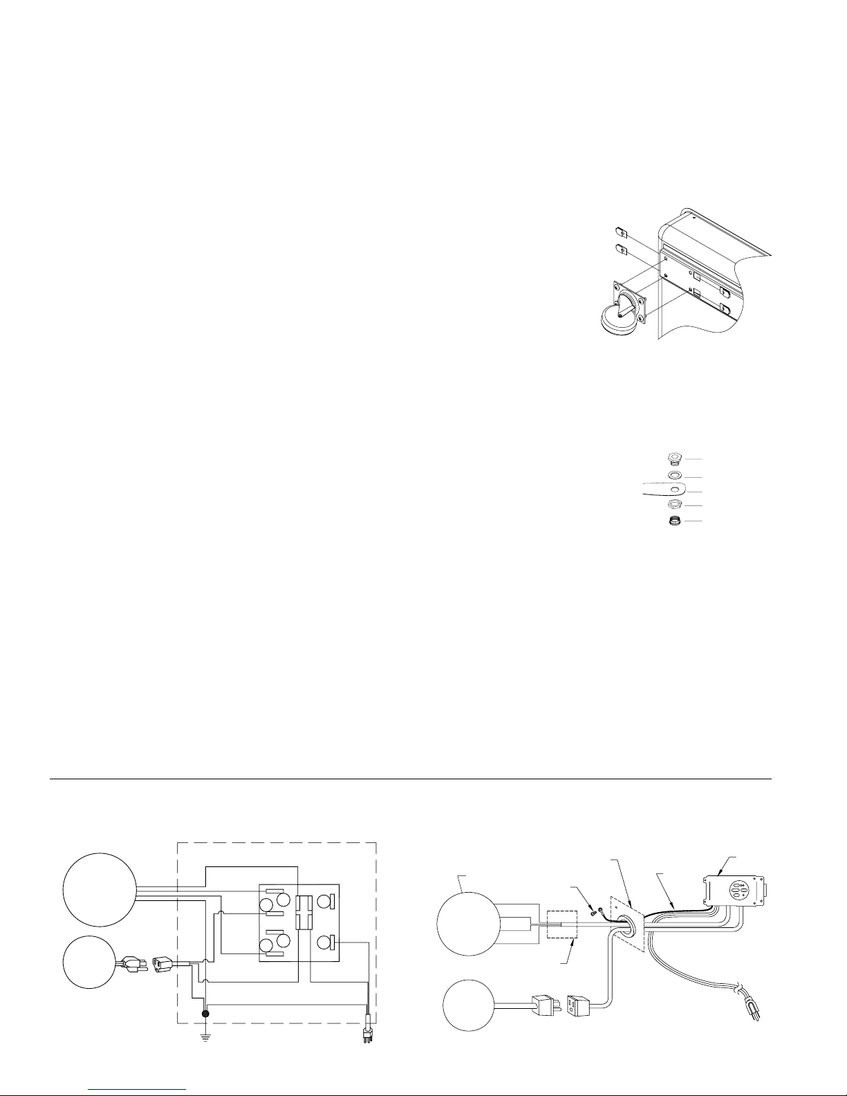
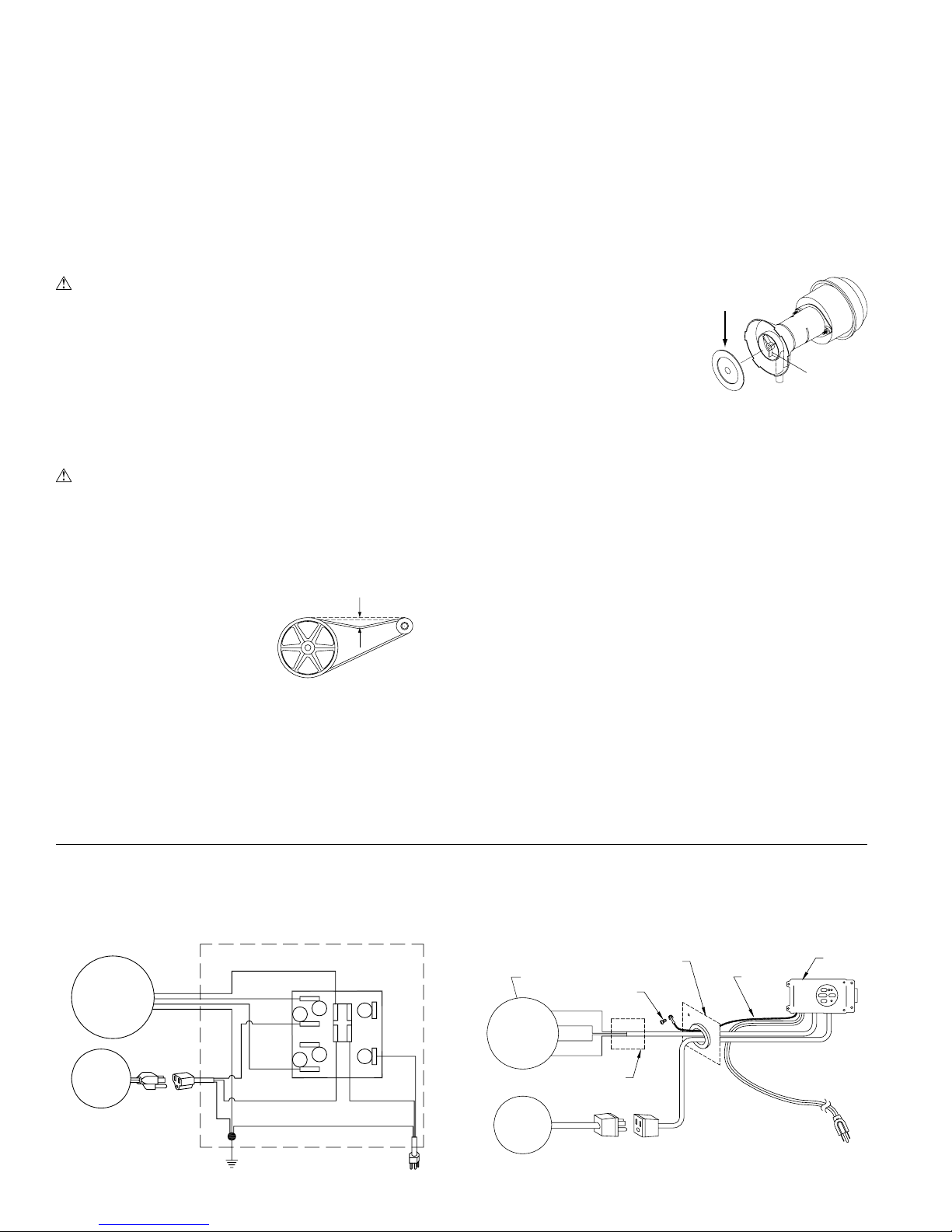
Conectar El Agua
• Instale el montaje de desagüe.
Quite la tuerca y pase la boquilla
por el agujero de la bandeja, colo-
cando la arandela de goma entre la
bandeja y la cabeza de la boquilla
(fig. 2). Coloque la tuerca en la bo-
quilla y atorníllela hasta que quede
apretada contra la parte inferior de
la bandeja. Atornille la tapa del
desagüe a la boquilla para retener
el agua.
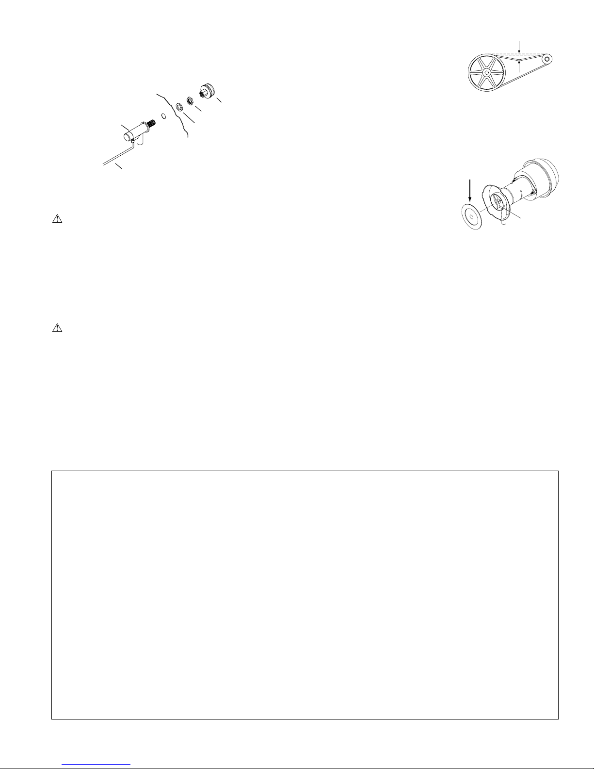
• Instale la válvula del flotador. Refiere a la figura 3. Instale
la válvula en el agujero que se encuentra en el poste de esquina
((R)M301Ay (R)M401A) o la reja lateral(M201A) usando latuerca
y arandela provistas. Si desea conectar unamanguera de jardín para
un suministro continua de agua, instale el adaptador de manguera
de jardín como se muestra en la figura. También se puede conectar
un tubo de 1/4 pulgadas.
Bandeja
Boquilla Roscada
Arandela De Goma
Tuerca
Tapa Del Desagüe
Fig. 2
Flotador
Varilla Del
Flotador
Arandela
Tuerca
Adaptador Para
Manguera De Jardín
Fig. 3
www.sylvane.com 1-800-934-9194

10 110522-1
• Cambie los filtros. Debe cambiar los filtros una o dos veces
durante cada temporada, según la duración de ésta. Al principio y
a mediados de la temporada, un filtro limpio es más absorbente y
eficiente y producirá un mayor volumen de aire frío.
• Limpie la bomba. Es necesario limpiar la bomba una vez al
principio de cada año. Por su propia seguridad, apague la unidad
y desconecte la unidad y la bomba. Quite el sujetador de plástico
de la montura y jale la bomba, deslizándola hacia usted. Quite la
base de la bomba (véase fig 5). Limpie la bomba. Dé le vuelta a
la hélice para verificar que se mueve libremente. Quite el pico de
la bomba y vea si está obstruido. Después de limpiar, reinstale la
base en la bomba. Presione
firmemente para asegurarse de
que es segura.Vuelva a colocar
la bomba en la unidad y fíjela
en su montura con el sujetador
de plástico. Esto impedirá que
se caiga la bomba al agua, lo
que dañaría el motor. No se
olvide de volver a conectar el
tubo de agua a la bomba.
•Mantenimiento General
• Desagüe el agua. Recomendamos desaguar el agua del enfriador
por lo menos una vez por semana. Quedando agua dulce en el
bandeja ayudará a prevenir la acumulación de la escala y depósi-
tos minerales en los filtros. Desagüe siempre toda el agua de la
unidad cuando no use el enfriador durante períodos prolongados,
especialmente al fin de la temporada.
• Desconecte la unidad de la electricidad cuando no sea utilizada
durante períodos extendidos.
• Cubra la unidad o almacénela adentro cuando no esta funcio-
nando.
Si usted sigue estas sugerencias en cuanto a instalación, operación y
mantenimiento, podrá disfrutar de muchos años de servicio eficiente
y satisfactorio de este enfriador. Si desea más información, su con-
cesionario tendrá mucho gusto en ayudarle con respecto a cualquier
duda o pregunta.
Esquemas Del Cableado
Mantenimiento
ADVERTENCIA: Antesde hacercualquier mantenimiento,
compruebe que la unidad esté apagada y desconectada de la
electricidad. Esto es por su seguridad.
Mantenimiento Anual
• Lubrique los cojinetes. Los cojinetes de la rueda (M401A y
RM401Asolamente) y el motor del ventilador deben ser lubricados
usando unas gotas de un aceite no detergente de densidad 20/30
una vez al año. No obstante, los motores sin tuberías para aceite
no necesitan ser lubricados. Estos motores son lubricados en la
fábrica de por vida y no requieren nunca ninguna lubricación.
PRECAUCION: No lubrique demás. El agregar demasiado
aceite puede ocasionar que se queme el motor, a causa del aceite
entrando al interior del motor.
• Compruebe la tensión de la correa. Esto se aplica solamente a
los modelos M401Ay RM401Aque tienen una correa. Los mode-
los M201A , M301A y RM301A
tienen motores de transmisiones
directas sin correas. Una fuerza
de 3 libras debe desviar la correa
3/4pulgadas (véase fig. 4). Ajuste
la correa si es necesario. Com-
pruebe el correa para saber si hay
grietas o desgaste y reemplácela
si es necesario.
Blanco-Común
Negro-Alto
Negro
Motor De
La Rueda
Bomba Rojo-
Bajo
Blanco-Común
Verde-Tierra
Verde
Interruptor
A
B
12
34
Acanalado-
Común
Liso
Verde
hélice
Quite
La Base
Fig. 5
Fig. 4
3 Libras
3/4 Pulgadas
Control Manual Control A Distancia
• Llene la bandeja con agua. Se puede llenar la unidad con agua
manualmente por hasta 3 horas de aire fresco. Para llenar automá-
ticament conecte una manguera de jardín al adaptador o un tubo
de 1/4 pulgadas al flotador.
Nota: No Sobrellene. Llene el agua hasta una altura máxima de
2 y 1/2 pulgadas (aproximadamente una pulgada por debajo del
borde superior de la bandeja). Si utiliza una manguera de jardín,
debe ajustar el flotador para que mantenga este nivel. Esto se puede
lograr doblando la varilla del flotador para arriba o para abajo.
Alto
Tierra
Común
Negro
Rojo
Verde
Blanco
Cable De
Tierra
Motor De
La Rueda
Motor
De La
Bomba
Panel De Ventilador Control
Tornillo
De Tierra
Bajo
Caja De Empalme
(RM301A)
www.sylvane.com 1-800-934-9194

11
110522-1
Garantía Limitada
La presente garantía se extiende al comprador original de un enfriador evaporativo instalado y utilizado bajo condiciones normales. No cubre daños ocurridos
por accidente, descuido o abuso por parte del propietario. No autorizamos que ninguna otra persona o representante asuma por nosotros cualquier otra o dife-
rente responsabilidad en relación con este producto.
Términos y Condiciones De La Garantía
Durante Dos Años a partir de la fecha de compra, reemplazaremos cualquier componente original proporcionado por Champion Cooler que falle debido a
cualquier defecto de material o mano de obra en la fábrica solamente.
Exclusiones De La Garantía
No somos responsables por reemplazar los filtros del enfriador. Estos son componentes desechables y deben cambiarse periódicamente. No somos responsables
por daños que resulten a consecuencia de alguna falla de funcionamiento.
No somos responsables por cualquier daño producido por el uso de suavizadores de agua, productos químicos, materiales desincrustantes, envolturas de plástico,
o si se usa en esta unidad un motor de mayor potencia de la que se indica en la placa de número de serie.
No somos responsables por el costo del servicio para diagnosticar la causa del problema ni por la mano de obra necesaria para reparar y/o reemplazar piezas.
Como Obtener Servicio Bajo Esta Garantía
Póngase en contacto con el Concesionario que le vendió el enfriador. Si por alguna razón usted no queda satisfecho con la respuesta por parte del Concesio-
nario, comuníquese con el departamento de servicio al cliente: Champion Cooler, 5800 Murray Street, Little Rock,Arkansas 72209. 1-800-643-8341. info@
championcooler.com.
Esta garantía limitada se aplica al comprador original solamente.
1. No llega corriente
• Fusible fundido
• Cortacircuito desac-
tivado
• Cable eléctrico
dañado
2. Correa muy floja o
apretada
3. Motor recalentado
• Correa muy apretada
• Cojinetes de la rueda
están secos
4. Motor parado
1. Insuficiente abertura
para que salga el aire
2. Poca tensión en la
correa
3. Filtros obstruidos
1. El agotamiento del aire
es inadecuado
2. Los filtros no están
mojados
• Filtros obstruidos
• Filtros agujereados
• Agujeros de los
canales obstruidos
• Bomba no funciona
1. Revise la corriente
• Cambie el fusible
• Restablecer el
cortacircuito
• Reemplace el cable
2. Ajuste la tensión de la
correa
3. Determine la causa
• Ajuste la tensión de
la correa
• Lubrique los cojine-
tes
4. Cambie el motor
1. Abra las ventanas o las
puertas para aumentar
el flujo de aire
2. Ajuste la tensión o
cambie la correa
3. Cambie los filtros
1. Abra más las ventanas
o puertas
2. Revise la distribución
de agua
• Cambie los filtros
• Acomode la paja en
el filtro
• Límpielos
• Cámbiela o límpiela
(Desconecte la
unidad)
Problema Causa Posible Remedio
La Localización De Averías
No arranca o
no sale aire
Sale poco
aire cuando
la unidad está
funcionando
Enfriamiento
inadecuado
Motor se apaga
y se enciende
Hace Ruido
Demasiada
humedad en la
casa
Olor a ence-
rrado, olor
desagradable
El agua está
drenando del
enfriador.
1. Voltaje deficiente
2. Demasiada tensión en
la correa
3. Eje del ventilador
atorado
4. Cojinetes secos
1. Cojinetes secos
2. Rueda roza contra caja
de la rueda
3. Partes sueltas
1. Insuficiente salida de
aire
1. Agua estancado en la
unidad
2. Los filtros tienen moho
o son obstruidos.
3. Los filtros son secos
• Agujeros del canal
tapados
• Bomba no trabaja
adecuada
1. El flotador no se ajusta
correctamente
2. El montaje de desagüe
se está escapando
1. Compruebe el voltaje
2. Ajuste la tensión de la
correa
3. Lubrique o cambie los
cojinetes (Desconecte
la unidad)
4. Lubrique los cojinetes
1. Lubrique los cojinetes
2. Inspeccione y alinee
(Desconecte la unidad)
3. Apriételas
1. Abra las puertas o las
ventanas
1. Desagüe y limpie los
filtros
2. Cambie los filtros
3. Revise la distribución
de agua
• Límpielos
• Reemplace o limpie
la bomba (Desco-
necte la unidad)
1. Ajuste el flotador
2. Apriete la tuerca y la
tapa de desagüe
Problema Causa Posible Remedio
Registre su producto en línea a: www.championcooler.com/eac/onlineregistration-eac.htm
www.sylvane.com 1-800-934-9194
Other manuals for M201A
1
This manual suits for next models
4
Table of contents
Languages: