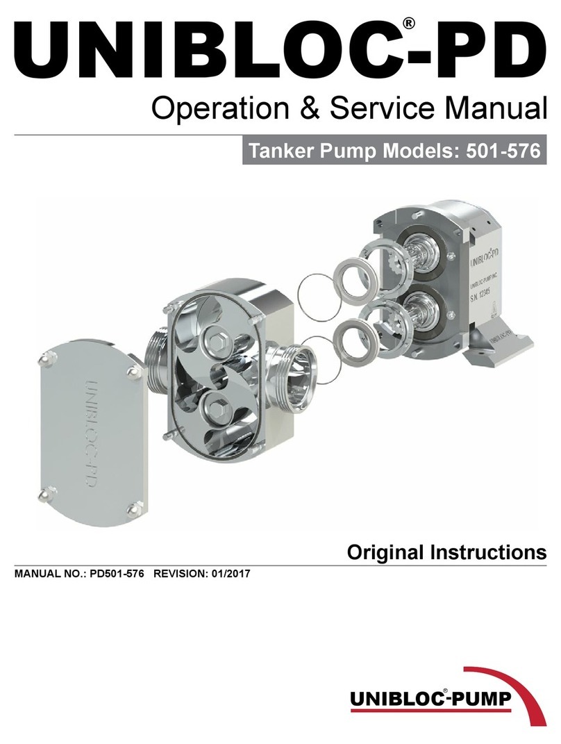
Unibloc-Pump UNIBLOC-PD Series Installation and operating instructions

Operation & Service Manual
UNIBLOC-PD
®
Models: 200-576
Original Instructions
MANUAL NO.: PD200-576 REVISION: 09/2019

Information contained in this manual is subject to change without notice
and does not represent a commitment on the part of Unibloc-Pump. No
part of this manual may be reproduced or transmitted in any form or by
any means, electronic or mechanical, including photocopying and
recording, for any purpose, without the express written permission
Unibloc-Pump.
Copyright © 2019 Unibloc-Pump.
All Rights Reserved.
Revision Date: 09/2019
Manual No.: PD200-576
Unibloc-Pump, Inc.
1701 Ashborough Road SE •Marietta, Georgia 30067 •USA
Tel 770-218-8900 E-Mail info@uniblocpump.com
www.uniblocpump.com
Unibloc-Pump R&H
Stromberger Strasse 197 •D-59269 Beckum •Germany
Tel +49-0-25-21/29918-42 E-Mail info@unibloc-rh.com
www.unibloc-rh.com

UNIBLOC-PD Operation & Service Manual: PD200-576 3
Contents
1.0 General ................................................................................................................5
1.1 Declaration of Conformity.................................................................................................. 5
1.2 General Description............................................................................................................ 7
1.2.1 Limitation .................................................................................................................................................. 8
1.2.2 Noise Emission ........................................................................................................................................ 8
1.2.3 Marking – CE ............................................................................................................................................ 8
1.2.4 Marking – Standard.................................................................................................................................. 8
2.0 Safety...................................................................................................................9
2.1 General ................................................................................................................................ 9
2.2 Safety Instructions ............................................................................................................. 9
3.0 Installation.........................................................................................................11
3.1 Handling and Storage....................................................................................................... 11
3.2 System Design .................................................................................................................. 12
3.3 Flushed Seal Arrangement .............................................................................................. 12
3.3.1 Single and Double Mechanical Seal Flushing/Cooling ...................................................................... 12
3.3.2 Double O-Ring Seal Flushing/Cooling ................................................................................................. 14
3.4 Pre-Start Check List ......................................................................................................... 14
4.0 Maintenance......................................................................................................15
4.1 Clean In Place, CIP ........................................................................................................... 15
4.2 Steam In Place, SIP........................................................................................................... 15
4.3 Maintenance Schedule and Recommended Spare Parts.............................................. 16
4.4 Shaft Seal Service............................................................................................................. 16
4.4.1 Single Mechanical Seal.......................................................................................................................... 17
4.4.1.1 UNIBLOC-PD 200-275 Single Mechanical Seal Removal........................................................................... 17
4.4.1.2 UNIBLOC-PD 200-275 Single Mechanical Seal Installation....................................................................... 17
4.4.1.3 UNIBLOC 300-575 Single Mechanical Seal Removal ................................................................................. 18
4.4.1.4 UNIBLOC 300-575 Single Mechanical Seal Installation ............................................................................. 18
4.4.1.5 UNIBLOC 501, 551, 576 Front Loaded Single Mechanical Seal Removal ................................................ 19
4.4.1.6 UNIBLOC 501, 551, 576 Front Loaded Single Mechanical Seal Installation ............................................ 19
4.4.2 Flushed Single Mechanical Seal........................................................................................................... 20
4.4.2.1 Flushed Single Mechanical Seal Removal.................................................................................................. 20
4.4.2.2 Flushed Single Mechanical Seal Installation.............................................................................................. 20
4.4.3 Double Mechanical Seal ....................................................................................................................... 21
4.4.3.1 Double Mechanical Seal Removal ............................................................................................................... 21
4.4.3.2 Double Mechanical Seal Installation ........................................................................................................... 22
4.4.4 Double O-Lip™ Seal............................................................................................................................... 23
4.4.4.1 UNIBLOC 200-575 Double O-Lip™ Seal Removal ..................................................................................... 23
4.4.4.2 UNIBLOC 200-575 Double O-Lip™ Seal Installation .................................................................................. 23
4.4.4.3 UNIBLOC 501, 551, 576 Front Loaded Double O-Lip™ Seal Removal ..................................................... 24
4.4.4.4 UNIBLOC 501, 551, 576 Front Loaded Double O-Lip™ Seal Installation ................................................. 24
4.4.5 Single O-Ring Seal ................................................................................................................................. 25
4.4.5.1 UNIBLOC 200-275 Single O-Ring Seal Removal......................................................................................... 25
4.4.5.2 UNIBLOC 200-275 Single O-Ring Seal Installation..................................................................................... 25
4.4.5.3 UNIBLOC 300-575 Single O-Ring Seal Removal......................................................................................... 26
4.4.5.4 UNIBLOC 300-575 Single O-Ring Seal Installation..................................................................................... 26
4.4.6 Double O-Ring Seal................................................................................................................................ 27
4.4.6.1 Double O-Ring Seal Removal....................................................................................................................... 27
4.4.6.1 Double O-Ring Seal Installation................................................................................................................... 27
4.4.7 UNIBLOC 200-575 Seal Installation – Final Step ................................................................................ 28
4.4.8 UNIBLOC 501 Series Seal Installation – Final Step ............................................................................ 29

4 UNIBLOC-PD Operation & Service Manual: PD200-576
4.5 Pump Bearing Housing Service ...................................................................................... 29
4.5.1 Bearing housing Disassembly.............................................................................................................. 30
4.5.2 Bearing housing Assembly ................................................................................................................... 30
4.5.2.1 Pump Assembly - Stainless Steel Rotors ................................................................................................... 30
4.5.2.2 Pump Assembly – Stainless Steel Rotors – Final Step ............................................................................. 31
4.5.2.3 Pump Assembly – QuickStripTM Rotors ...................................................................................................... 31
4.6 Relief Valve Cover Service............................................................................................... 32
4.6.1 Relief Cover Model #46 ......................................................................................................................... 32
4.6.2 Relief Cover Model #B ........................................................................................................................... 33
4.7 Compac Pump Series Service ......................................................................................... 34
4.8 Troubleshooting ............................................................................................................... 35
5.0 Technical Data ..................................................................................................37
5.1 General Dimensions and Weights................................................................................... 37
5.2 Lubricants and Bearing housing Oil Specication ....................................................... 38
5.3 Tools and Torque Requirements .................................................................................... 39
5.3.1 Special Tools .......................................................................................................................................... 39
5.4 Rotor Clearances ............................................................................................................. 40
6.0 Pump Identication and Spare Parts..............................................................41
6.1 Pump Identication ......................................................................................................... 41

UNIBLOC-PD Operation & Service Manual: PD200-576 5
1.0 General
1.1 Declaration of Conformity
Original Declaration of Conformity
According to New Approach Machine Directive 2006/42/EC
Manufacturer
UNIBLOC-PUMP, Inc.
Flowtech Div.
1701 Ashborough Road
Marietta, GA 30067-8925
USA
Manufacturer
UNIBLOC-PUMP AB
Lantvarnsgatan 4
652 21 Karlstad
SWEDEN
Declares hereby
That the following product(s) if ordered with CE compliance are meeting the requirements set forth in EC
Directive 2006/42/EC.
If the product is modified without our written permission, or if the safety instructions in the instruction
manuals are not being followed, this declaration becomes invalid.
Machine Description: Rotary Lobe Pump
Product Denomination: UNIBLOC®-PD
Model/Type: PD200-677
Standards: Applicable Harmonized Standards
oEN 809+A1 2009 Pumps and Pump Units for Liquids –
Common Safety Requirements
Technical file for this machinery is retained at the above address.
Bhavesh Patel Date: October 15, 2015
QA Manager
UNIBLOC-PUMP, Inc. Marietta, Georgia, United States

6 UNIBLOC-PD Operation & Service Manual: PD200-576
Original Declaration of Conformity
According to New Approach Machine Directive 2006/42/EC
Manufacturer
UNIBLOC-PUMP, Inc.
1701 Ashborough Road
Marietta, GA 30067-8925
USA
Manufacturer
UNIBLOC-PUMP AB
Lantvarnsgatan 4
652 21 Karlstad
SWEDEN
Declares hereby
That the following product(s) if ordered with CE compliance are meeting the requirements set forth in EC
Directive 2006/42/EC.
If the product is modified without our written permission, or if the safety instructions in the instruction
manuals are not being followed, this declaration becomes invalid.
Machine Description: Rotary Lobe Pump Assembly
Product Denomination: UNIBLOC®-PD & GP ASSEMBLY
Model/Type: PD200-677; GP200-450
Directives: Applicable Directives
oElectromagnetic Compatibility Directive 2004/108EC
oLow Voltage Directive 2006/95/EC
Standards: Applicable Harmonized Standards
oEN 809+A1:2009 Pumps and Pump Units for Liquid –
Common Safety Requirements
oEN 60034 Rotating Electrical Machinery
oEN 60038 IEC Standard Voltages
EN 60204-1:2006 Safety of Machinery, Electrical Equipment
of Machines.
Technical file for this machinery is retained at the above address.
Bhavesh Patel Date: October 15, 2015
QA Manager
UNIBLOC-PUMP, Inc. Marietta, Georgia, United States

UNIBLOC-PD Operation & Service Manual: PD200-576 7
1.2 General Description
UNIBLOC-PD is a positive displacement rotary lobe pump. It may be supplied with a drive unit (gure 1.0) or without a drive
unit (gure 1.1). When supplied with a drive unit it is called UNIBLOC-PD ASSEMBLY. Figure 1.0 indicates various parts of
an assembly. UNIBLOC-PD can be supplied in 4 dierent series; 5000 series with stainless steel bearing housing, 4000A with an
anodized aluminum bearing housing or 4000B with a painted aluminum bearing housing and 3000 series with steel bearing hous-
ing. Dierent models are available from each series. Table 1.0 shows the pump bearing housing and model relation. Each model
can be mounted with the inlet and outlet ports in horizontal or vertical orientation. The orientation can be modied using either a
foot for horizontal or pedestal for vertical. Port orientation should be specied when ordering.
Figure 1.0 Figure 1.1
Bearing
housing
Pump
Model
Bearing
housing
Pump
Model
Bearing
housing
Pump
Model
Bearing
housing
Pump
Model
Bearing
housing
Pump
Model
200 Size 200-0 300 Size 300 400 Size 400 500 Size 500 501 Size 501
200 Size 200 300 Size 350 400 Size 450 500 Size 550 501 Size 551
200 Size 250 500 Size 575 501 Size 576
200 Size 275
Table 1.0
The UNIBLOC-PD port positions are designed to accommodate both vertical and horizontal product ow. Model 200-275 has a
bracket with an integrated foot and can be rotated 90° to change port orientation. Models 300-575 have a pre-drilled bearing hous-
ing. This allows custom installation, standard feet for horizontal ports, or a standard pedestal for vertical port orientation.
The pump is designed to operate in both directions without modications. See gure 1.2
PRODUCT
FLOW
PRODUCT
FLOW
Figure 1.2

8 UNIBLOC-PD Operation & Service Manual: PD200-576
1.2.1 Limitation
The pump should be used for the duty for which it has been specied. The operating pressure, speed and temperature limits have
been selected at the time of order and MUST BE ADHERED TO. These details are stated on the original order documentation. If
not available, documentation may be obtained from your supplier by referencing the pump serial number and/or invoice number.
1.2.2 Noise Emission
Under certain operating conditions, pumps and/or drives and/or the systems within which they are installed can produce sound
pressure levels that exceed 80dB. In such cases ear protection should be used.
1.2.3 Marking – CE
Figure 1.3 shows the tag that is attached on the pump bearing housing.
If the tag were to be lost for any reason you can nd the pumps serial number
machined on the side of the bearing housing. See gure 1.4
Always state the pump model and/or serial number when asking for assistance.
1.2.4 Marking – Standard
Standard marking is machined on the side of pumps’ bearing housing.
See gure 1.4 for details. Pump size is machined on rotor housing next to the ports.
Figure 1.4
Figure 1.3

UNIBLOC-PD Operation & Service Manual: PD200-576 9
2.0 Safety
2.1 General
This information must be read carefully before installation, operation or servicing. The safety instruction must always be availa-
ble for the pump operator. The following symbols are used.
WARNING: Indicates instructions that can aect personal safety if not followed.
WARNING: Indicates electrical voltage instructions that can aect personal safety if not followed.
ATTENTION: Indicates instructions to be considered for safe operation and to protect the pump and
pump unit.
2.2 Safety Instructions
Incorrect installation, operation or maintenance of the equipment can cause serious personal injury and/or damage to the equip-
ment and will invalidate the warranty. Make sure the pipes are well supported as the pump is not meant to serve this purpose.
Keep in mind that pipes lled with liquid are very heavy. See gure 2.2.1 for recommended pipe layout.
Figure 2.2.1
Pump or pump assembly must be electrically connected by authorized personnel, follow the motor instructions supplied
in case of assembly.
Never operate the pump if the front cover and/or suction/discharge pipe-work are not in place. Make sure they are prop-
erly installed, see gure 2.2.1. Likewise, never operate the pump if other protection such as coupling and shaft guards are
missing or incorrectly installed.
Never stick your appendages or other foreign objects inside the rotor housing, connections to the rotor housing, or in the
back cover if there is any possibility that the pump shafts may rotate.
Do not exceed the pump’s maximum operating pressure, speed or temperature. Do not modify the operating parameters/
system for which the unit was originally supplied for without rst consulting your local supplier.
Pump installation and operation must always comply with prevailing health and safety regulations.
WRONG RIGHT
ATTENTION

10 UNIBLOC-PD Operation & Service Manual: PD200-576
Always make sure the alignment with the drive unit is within proper tolerances. Misalignment between the pump, drive
and coupling will result in premature wear, increased operating temperature and noisier environment.
See gure 2.2.2 for vertical misalignment: Place shims under pump or drive; 0.25mm (0.01inch) max deviation.
See gure 2.2.3 for horizontal misalignment: Move pump or drive horizontally; 0.25mm (0.01inch) max deviation.
See gure 2.2.4 for angular misalignment: Rotate pump or drive; 1° max deviation
Avoid any direct contact with hot surfaces of the pump or drive unit. If the surface temperature of the system exceeds
68°C, the system must be marked with a warning sign for “hot surface.”
ALWAYS DISCONNECT THE POWER SUPPLY when performing any kind of maintenance. Make sure the power can
not be switched by locking it. Allow the pump and associated parts to cool down to a safe handling temperature.
Never operate the pump with either the suction side or the pressure side blocked.
Never operate the pump without the front cover installed properly
Always make sure any safety/relief valves are depressurized or relieved before dismantling.
Always ensure correct rotation of pump with ow direction before start.
Installation of safety equipment to prevent pump from exceeding maximum allowable pressure is recommended.
If an integrated safety relief valve is installed, do not allow extended periods of recirculation through the valve.
UNIBLOC-PUMP can either integrate a safety valve with the front cover, or supply one as a separate unit.
Please contact your supplier.
Installation of a non-return device is recommended to prevent reverse ow in the pump when it is being turned
o. UNIBLOC-PUMP can supply a check valve as non-returning device. Please contact your supplier.
Check the pump and motor assembly for adequate oil prior start up.
Make sure the pump and pipe systems are clean and free from debris or any foreign material before start up.
Do not install the pump into a system where it may run dry (i.e. without a supply of pumped media) unless it is
assembled with a ushed shaft seal that is properly installed with a fully operational ushing system.
Installation of pressure gauges/sensors in conjunction with the pump’s suction and discharge connections is
recommended to be able to monitor the pump’s pressure.
When cleaning manually or by CIP, SIP methods, the operator must ensure that a suitable procedure is used in
accordance with the systems requirements.
If operating with a pulley, proper support must be selected to prevent excessive bearing wear and bending of the
shaft. See gure 2.2.5.
Additional safety guards are a must.
Figure 2.2.2 Figure 2.2.3 Figure 2.2.4
Figure 2.2.5
ATTENTION
ATTENTION
ATTENTION
ATTENTION
ATTENTION
ATTENTION
ATTENTION
ATTENTION

UNIBLOC-PD Operation & Service Manual: PD200-576 11
3.0 Installation
3.1 Handling and Storage
Caution must be taken when lifting the pump or pump unit. For all parts over 20kg we recommend the use of a lifting
device or lifting arrangement when unpacking or moving. Check the weight guide in section 5.0 for details. See gure
3.0 and 3.1 for lifting guidance.
Vertical Port Mounting Horizontal Port Mounting Horizontal Port Mounting Vertical Port Mounting
Figure 3.0 Figure 3.1
When you receive your product please follow these steps.
• Check packaging for any damage in transit.
• Check the packing slip against received goods.
• If an assembly, make sure the manual for the drive unit is included.
• Visually inspect the product for any signs of damage.
• Report any damage immediately to the carrier.
If installation of the pump is delayed, store and protect the unit properly by:
• Not removing plastic port protectors.
• Selecting a clean, dry storage location free from vibration. In a moist or dusty atmosphere, further protect the pump/as-
sembly with suitable cover.
• Rotating the pump or pump assembly by hand every week, to prevent bearing damage.

12 UNIBLOC-PD Operation & Service Manual: PD200-576
3.2 System Design
When a pump is to be incorporated in a system, it is considered good practice to minimize the length of the pipes and the number
of ttings and any other restrictions to product ow. Always consider the following when designing a system:
• Conrm the Net Positive Suction Head-NPSH available from the system exceeds the NPSH required from the pump to
ensure smooth operation and avoid cavitation.
• Avoid suction lifts and manifold/common suction lines for two pumps running in parallel, as this may cause vibration or
cavitation.
• Protect the pump from unintended blockage from nuts, bolts, welding slag, etc, by installing a strainer. Also protect the
pump from unintended operation against a closed valve by installing a safety/pressure relief valve. Strainers and relief
valves can be provided by UNIBLOC-PUMP.
• Install monitoring equipment on suction and pressure side of pump for diagnostic purposes.
• Install shut-o valves on suction and pressure side to isolate pump when service is necessary.
• Make sure the pipes are well supported. Do not use the pump to support the piping. See gure 2.3.1
• Make the necessary piping arrangement if pump is supplied with a ushed seal or if the housing is jacketed for heating/
cooling.
• Do not expose pump to rapid temperature changes, this may seize the pump as a result from thermal shock.
• Allow at least 1m (3feet) free space around the pump for easy maintenance access.
Figure 3.2.1 shows a typical recommended design and required components for safe operation of the pump. All components are
available from UNIBLOC-PUMP. Contact your supplier.
3.3 Flushed Seal Arrangement
The ushed seal arrangement cools and lubricates the shaft seal area. All ushed seals must be installed in a proper system; oth-
erwise the seal will NOT OPERERATE CORRECTLY. The ushing system also works as a barrier between the environment and
the pumped media.
3.3.1 Single and Double Mechanical Seal Flushing/Cooling
Flushing systems are normally not included with the pump. Connections to the seal housings are 1/8” NPTF.
It is important that:
• The ush system is correctly installed and connected, see gure 3.3.1 and 3.3.2 for recommendations.
• A compatible ushing uid is used and supplied at the correct pressure and ow rate. If the discharge pressure uctuates
set the pressure to suit maximum condition.
Double mechanical ushed seal pressure: 1bar (15psi) higher than the discharge pressure of the pump
Single mechanical with ushed housing max pressure: 0.5bar (7psi)
Minimum ow rate required per seal: 1lpm (0.3gpm) or a rate that keeps seal temperature within 5°C (9°F)
PRESSURE RELIEF VALVE
SHUT OFF VALVE
STRAINER
PRESSURE GAUGE
FLOWFLOW
SHUT OFF VALVE
Figure 3.2.1
ATTENTION

UNIBLOC-PD Operation & Service Manual: PD200-576 13
• It includes shut-o valves and check valves in the system so that the ush can be turned o and stop unwanted substance
from owing in the wrong direction.
• It includes monitoring equipment such as a pressure gauge in the system to ensure correct pressure is obtained.
• The ushed uid is owing before or at the same time the pump is engaged, and turned o after or at the same time the
pump is disengaged.
VERTICAL PUMP PORTS
(recommended piping arrangement)
HORIZONTAL PUMP PORTS
(recommended piping arrangement)
FLUSH
OUTLET
PRESSURE
GAUGE
FLUSH
OUTLET
CONTROL VALVE
(i.e diaphragm valve)
PRESSURE
GAUGE
FLUSH
INLET
CHECK
VALVE SHUT OFF
VALVE
CONTROL VALVE
(i.e diaphragm valve)
FLUSH
INLET
CHECK
VALVE
SHUT OFF
VALVE
Figure 3.3.1
FLUSH
OUTLET
CONTROL VALVE
(i.e diaphragm valve)
ALTERNATE PIPING ARRANGEMENTS
FLUSH
OUTLET
PRESSURE
GAUGE
FLUSH
INLET
PRESSURE
GAUGE
SHUT OFF
VALVE
CHECK
VALVE
FLUSH
INLET
SHUT OFF
VALVE
CHECK
VALVE
CONTROL VALVE
(i.e diaphragm valve)
Figure 3.3.2

14 UNIBLOC-PD Operation & Service Manual: PD200-576
3.3.2 Double O-Ring Seal Flushing/Cooling
The ushing system may be arranged the same as the double mechanical seals, shown in gure 3.3.1 and 3.3.2. The double o-ring
seals may also be lubricated with grease if the pump application justies doing so. In this case, the seal ush chambers are lled
through grease nipples with approved grease that is suitable for use with the pumped media. The chambers must be lled com-
pletely for proper operation. This can be accomplished by over pressurizing the chambers such that grease will be squeezed out
of the seals along the shafts and into the rotor housing. The amount of grease in the seal chambers must be monitored daily, and if
the pump is used in constant duty applications, it should be checked several times every 24 hour period.
3.4 Pre-Start Check List
• Check the pipes to make sure they have been purged of debris.
• Check all obstructions to make sure they have been removed from pipe or pump.
• Check pump connections and make sure they are tight.
• Check lubricant levels to make sure they are correct.
• Check that safety guards are in place.
• Check inlet and outlet valve to make sure they are open and functional.
• Check the seal ushing is connected and activated, if applicable.

UNIBLOC-PD Operation & Service Manual: PD200-576 15
4.0 Maintenance
BEFORE ANY MAINTENANCE TAKE PLACE: TURN OFF POWER SUPPLY TO THE MOTOR.
4.1 Clean In Place, CIP
The pump can be manually cleaned or by Cleaned In Place (CIP). The following is an example of suggested CIP procedure. How-
ever, specic advice for each application can be obtained from your pump supplier.
If the temperature dierence between the process liquid, or the pump, and the cleaning media is greater than 100º C (180º F), stop
the pump and then introduce the cleaning liquid. If the liquid is not gravity fed and the pump must draw the liquid from a supply
vessel, run the pump until it is lled and then stop. Allow the pump to adjust to the cleaning liquid temperature and then continue
running the pump at normal speed. If the pump has double mechanical seals, they must be continued to be ushed during the CIP
process. The length of time necessary to clean the pump and the type of liquid used is dependent on the type of process liquid and
its characteristics.
Never touch the pump or the pipelines as they can be extremely hot.
Always use rubber gloves and protective goggles if handling caustic substances.
The rotors and shaft seals in the pump have been selected for specic temperature and pressure conditions. Ver-
ify with UNIBLOC-PUMP or the documentation supplied with the pump that the operating parameters are not
exceeded.
Always rinse well with clean water after using cleaning agent.
4.2 Steam In Place, SIP
The pump can be manually cleaned or cleaned with Steam In Place (SIP). Following is an example of suggested SIP procedure.
However, specic advice for each application can be obtained from your pump supplier.
Stop the pump and introduce steam into the system. If the pump must be operated, allow it to adjust to the steam temperature and
then run it between 50-100 rpm. If the pump has double mechanical seals, they must be continued to be ushed during the SIP
process. The length of time necessary to steam the pump is dependent on the type of process liquid used and its characteristics.
After the SIP process is complete, allow the pump to return to ambient temperature or to the temperature of the process liquid.
Resume normal operation to remove condensate or to begin pumping another media.
Never touch the pump or the pipelines as they can be extremely hot.
Always use rubber gloves and protective goggles if handling caustic substances.
The rotors and shaft seals in the pump have been selected for specic temperature and pressure conditions. Ver-
ify with UNIBLOC-PUMP or the documentation supplied with the pump that the operating parameters are not
exceeded.
Always rinse well with clean water after using cleaning agent.
ATTENTION
ATTENTION
ATTENTION
ATTENTION

16 UNIBLOC-PD Operation & Service Manual: PD200-576
4.3 Maintenance Schedule and Recommended Spare Parts
It is recommended to install pressure gauges on both sides of the pump so that any problems with the pump or pipelines can be
monitored. It is also recommended to have shut-o valves on both sides for easy isolation of pump if manual service is required.
The UNIBLOC bearing housing is supplied permanently lubricated with nitrile seals. However, for certain applications and at the
user’s request, drain plugs and a vent will be supplied. When applications exceed constant service temperatures of 180º C (356º F)
a vent and high temperature lubricant must be used. For such cases, contact UNIBLOC-PUMP or your supplier for an adequate
service schedule.
Recommended weekly maintenance control to include:
• Control of oil levels in pump bearing housing and gear reducer. (Change once per year or after 2000 hours of operation,
whichever comes rst.)
• Control of oil seal leakage.
• Control of shaft seal leakage.
• Control of pump medium leakage.
Allow the pump to cool down after shut down prior to inspection.
Recommended spare parts
• 1 set of shaft seals Qty 2
• 1 set of front oil seals Qty 2
• 1 set of rear oil seals Qty 1
• 1 wet-end o-ring kit Qty 1 (5 o-rings)
• 1 wet-end o-ring kit (for Metal Rotors) Qty 1 (5 o-rings)
4.4 Shaft Seal Service
DISENGAGE POWER TO THE MOTOR before proceeding with the following steps. If the pump is connected to
piping, depressurize the system and close valves on both the suction and discharge sides to isolate the pump from the
rest of the system. Disconnect the piping from the pump. If service is to be performed while the pump is still mounted
to the system, disconnect the motor drive coupling or the electrical connection to the motor.
To aid in the removal and installation of the shaft seals, use plastic mounting sleeves with the same diameter as
the shafts seal area. The sleeves also protect the seals from the shaft splines. They can be obtained from UNI-
BLOC-PUMP. Contact your supplier for details.
Remove the front cover nuts (16) and the front cover (2). If the pump has polymer rotors (3b) they can be removed by sliding
them o the shafts. If the rotors are stainless steel (3a), place a nonmetal object between
the rotors to keep them from turning. Unscrew the rotor bolts (14a) and then slide the rotors
o the shafts. If the rotors will not slide o they can be removed simultaneously with the
rotor housing (1). Unless they are being replaced, DO NOT USE PLIERS OR CHANNEL
LOCKS TO REMOVE THE ROTORS. They will be damaged. See the following sections
for further instructions to remove the rotor housing.
Figure 4.4.1
ATTENTION
ATTENTION

UNIBLOC-PD Operation & Service Manual: PD200-576 17
4.4.1 Single Mechanical Seal
This type of shaft seal is used in most applications with products that have a viscosity of less than 1,000 cPs. The maximum
rotational speed of this seal is 1500 rpm and the maximum service pressure is 13.5 bar (195 psig). The seal materials available are
stainless steel, carbon, silicone carbide, and tungsten. The standard o-rings supplied in these seals are FDA-viton or FDA-EPDM.
These can be replaced with other materials upon request.
UNIBLOC-PD 501 Series has front loaded seals. This seal comes with dierent seal face combinations. (See drawing G812B for
details.) Maximum shaft rotational speed for this seal is 2.4 m/s (7.8 ft/s) or 800rpm and the maximum service pressure should not
exceed 15 bar (220 psig). Maximum and minimum temperature limits are +160°C (320°F) and -15°C (5°F).
4.4.1.1 UNIBLOC-PD 200-275 Single Mechanical Seal Removal
Loosen and remove the acorn nuts from the Rotor Housing. Loosen the Threaded Studs by locking two M6 nuts against each
other on the exposed threaded stud ends. Remove the Rotor Housing by pulling on the ports or by tapping gently with a rub-
ber mallet. Do not rock the housing back and forth excessively. This can cause the seals to break. Remove the Stationary Seal
Faces and Stationary Seal O-Rings by pulling them out of the rotor housing. Remove the Rotating Seal Faces, the Rotating
Seal O-Rings, and Rotating Seal Washers by sliding them o the shafts. To avoid damage, carefully handle and store the loose
Stationary Seal Faces and the Rotating Seal Faces so that their lapped sealing surfaces do not get scratched.
4.4.1.2 UNIBLOC-PD 200-275 Single Mechanical Seal Installation
If missing, insert the Rotor Housing Pins into the rotor housing and the Shaft Pins into the shafts. Coat the shafts and rotor
housing bores with a product compatible lubricant. Place the Rotating Seal O-Rings in the Rotating Seal Face rst, and then
the Rotating Seal Washers. Slide the Rotating Seal Rings, slotted side rst, onto the shafts. Place the Wave Springs between
the Rotor Housing Pins. Place the Stationary Seal O-Rings in the groove of the Stationary Seal Faces. Align the slots of the
Stationary Seal Faces with the Rotor Housing Pins in the rotor housing. Push the Stationary Seal Faces into the rotor housing,
o-ring side rst. Press several times to make sure they slide easily. Place a product compatible lubricant on the sealing surfaces.
Proceed to section 4.4.7 to complete the installation.
Stationary Seal O-Rings
Wave Springs
Stationary Seal Faces
Rotating Seal Faces
Rotating Seal O-Rings
Rotating Seal Washers
Shaft Pins
Rotor Housing Pins
Threaded Studs
Rotor Housing
UNIBLOC-PD 200-275 with Single Mechanical Seals

18 UNIBLOC-PD Operation & Service Manual: PD200-576
4.4.1.3 UNIBLOC 300-575 Single Mechanical Seal Removal
Loosen the Stud Nuts (item 43 in Figure 4.4.1). Remove the Rotor Housing by pulling on the ports or by tapping gently with
a rubber mallet. Do not rock the Rotor Housing back and forth excessively. The seals may break. The Seal Retaining Rings,
the Bolts, the Stationary Seal Faces, and the Stationary Seal O-Rings will all come o with the Rotor Housing. Unscrew the
Bolts to remove the Seal Retaining Rings, the Stationary Seal Faces, and the Stationary Seal O-Rings. Slide the Rotating Seal
Faces and the Rotating Seal O-Rings o the shafts. To avoid damage, handle and store the loose Stationary Seal Faces and Ro-
tating Seal Faces so that their lapped sealing surfaces do not get scratched. If not being replaced, the Drive Collars may remain
on the shafts, otherwise loosen the set screws and slide them o the shafts. UNIBLOC-PD 500 Series may use wear sleeves. See
section 4.4.4.1 sketch.
4.4.1.4 UNIBLOC 300-575 Single Mechanical Seal Installation
The shafts and the rotor housing bores should be cleaned before installing the seal components. Slide the Drive Collars on the
shafts. Moisten the Rotating Seal O-Rings with water or coat them with a lubricant that is acceptable for use with the product.
Slide the Rotating Seal O-Rings onto the shafts and then the Rotating Seal Faces, slotted sides rst. Align the slots in the Rotat-
ing Seal Faces with the pins in the Drive Collars. Push the Rotating Seal Faces against the Drive Collars so that the Rotating
Seal O-Rings seat properly. Place the Stationary Seal O-Rings (front & outer) on the Stationary Seal Faces. Only lubricate
these o-rings with water or alcohol. Push the Stationary Seal Faces into the rotor housing so that they seat at with the step in the
housing. Some applications require pins to be used in the Stationary Seal Faces. When placing them in the rotor housing align
the pins with the holes in the rotor housing and press them in. Do not use objects that will scratch the Stationary Seal Faces’ seal
surface to push them in. Place a product compatible lubricant on the sealing surfaces. If Seal Retaining Rings were supplied with
the pump, bolt them to the rotor housing. Proceed to section 4.4.7 to complete the installation. After installing the housing push
the Drive Collars toward it. Compress the Wave Springs while leaving a 2-3mm (0.08”-0.12”) gap between the Drive Collars
and the Rotating Seal Faces. Tighten the Drive Collar set screws. UNIBLOC-PD 500 Series may use wear sleeves. See section
4.4.4.1 sketch.
UNIBLOC-PD 300-575 with Single Mechanical Seals

UNIBLOC-PD Operation & Service Manual: PD200-576 19
4.4.1.5 UNIBLOC 501, 551, 576 Front Loaded Single Mechanical Seal Removal
Remove the Shaft O-rings (item 27 in Figure 4.4.1) located behind the shaft splines. Use two long at head screwdrivers 180º
apart to pry the Shaft Sleeve out of the Rotor Housing. Use razor blade or sharp at head screwdriver to remove the Rotating
Seal Face from the Shaft Sleeve. Remove Stationary Seal Face from Seal Retaining Ring by hand.
4.4.1.6 UNIBLOC 501, 551, 576 Front Loaded Single Mechanical Seal Installation
The shaft and rotor housing bores should be cleaned before installing the seal components. Before installing components, note
the location of the dowel pins on the Seal Retaining Ring. Small ink markings can be made on the surface of the Rotor Housing
to show pin locations. Replace and lubricate the Retaining Ring O-Ring.
Take the Stationary Seal Face and lubricate the Stationary Seal O-Ring already installed. Note location of pin slots on the
Stationary Seal Face. Ink markings can be made on surface of Rotor Housing to show location of pins and similar markings can
be made on seal face to show location of pin slots. Align the Stationary Seal pin slots with the Seal Retaining Ring pins. Evenly
hand press the Stationary Seal Face until fully seated. Stationary Seal Face will be fully seated once a spring compression can
be felt.
Place the Rotating Seal O-Ring on the stepped side of the Rotating Seal Face and lubricate. While aligning the Rotating Seal
Face pin slots with the Shaft sleeve pins, hand press the Rotating Seal Face into the Shaft Sleeve until fully seated. Lubricate
the Shaft Sleeve O-Ring located in the inner diameter of the Shaft Sleeve. Aligning the pin slots on the Shaft Sleeve with the
pins on shaft (item 90 in Figure 4.4.1), hand press the Shaft Sleeve(with Rotating Seal installed) evenly until seated and spring
tension can be felt. Spring tension will be set by installation of rotor onto shaft.
Shaft Sleeve O-Rings
Shaft Sleeves
Rotating Seal O-Rings
Rotating Seal Faces
Stationary Seal Faces
Retaining Ring O-Rings
Rotor Housing
Wave Springs
Seal Retaining Rings
Bolts
Stationary Seal O-Rings
UNIBLOC-PD 501, 551, 576 with Single Mechanical Seals

20 UNIBLOC-PD Operation & Service Manual: PD200-576
4.4.2 Flushed Single Mechanical Seal
The ushed single mechanical seal uses the same stationary mating ring, rotating seal nose ring, spring, and o-rings as the single
mechanical seal discussed in section 4.4.1. The drive collar is dierent, however. The ushed single mechanical is not available
for UNIBLOC 200-0, 200, 250, and 275. See section 3.3 for more information about ushing systems.
4.4.2.1 Flushed Single Mechanical Seal Removal
Disconnect the ush tubing from the ush housings (55). Loosen the set screws
(D) by inserting an allen wrench into the ush housing port holes. Loosen the
stud nuts (item 43 in Figure 4.4.1). Remove the rotor housing (1) by pulling on
the ports or by tapping gently with a rubber mallet and lay it rotor cavity down
so that the seals face up. Do not rock the housing back and forth excessively
or let it come in contact with the shaft splines. The seals may break. The entire
seals with the ush housings will come o intact with the rotor housing. Un-
screw the bolts (32) to remove the ush housings (55), the lip seals (56), and
the ush housing o-rings (37). The remaining seal components may now be re-
moved. To avoid damage, handle and store the loose seal nose rings (B) and the
mating rings (A) so that their lapped sealing surfaces do not get scratched. To
remove the lip seals (56), place the ush housings so that they are supported at
the bolt holes not at the at the o-ring (37) location. This can be done by placing
the ush housings, after all other seal parts have been removed, back into the
rotor housing seal bores. Push or tap the lip seals with a tube to remove them.
4.4.2.2 Flushed Single Mechanical Seal Installation
Place the mating ring o-rings (33a) in the rotor housing seal bores. Only lubricate these o-rings with water or alcohol. Push the
mating rings into the rotor housing so that they seat at with the step in the housing. Do not use objects that will scratch the
mating rings’ seal surface to push them in. Check the drive collars (C) for wear at the lip seal location. If a groove is present, the
drive collars may need to be replaced. If the lip seals (56) have been removed, place the ush housings (55) so that the o-ring
groove edges face up. Lubricate the lips and the outer diameters of the lip seals. Push the lip seals, spring sides facing up, into
the ush housings with a tube that is the same diameter as the lip seals. Place the o-rings (37) into the o-ring grooves. Lubricate
the shafts, the outside of the plastic mounting sleeves, and the drive collars at the lip seal location. Slide the ush housings on the
drive collars. Slide the ush housings with the drive collars, seal nose o-rings (33b), and the seal nose rings (B), slotted sides rst,
on the plastic mounting sleeves. Align the slots with the pins in the drive collars and push the seal nose rings so that the o-rings
(33b) seat properly. Place a product compatible lubricant on the sealing surfaces. Rotate the ush housings so that its port holes
align with at least one set screw. Lubricate the o-rings (37) and mount the seal cartridge assemblies on the rotor housing. Tighten
the bolts (32). See section 4.4.7 to complete the installation.
This manual suits for next models
15
Table of contents
Other Unibloc-Pump Water Pump manuals
Popular Water Pump manuals by other brands

Nordson
Nordson PermaFlo 815 User's product manual

ITT
ITT GOULDS PUMPS 3408 Installation, operation and maintenance manual

Pentair
Pentair BERKELEY TMH Series Owner's/operator's manual

ProMinent
ProMinent gamma/l Installation and configuration manual

INPRO
INPRO Micro Domestic installation guide

Graco
Graco Reactor 2 Series Operation

Desmi
Desmi SA Series Operation and maintenance instructions

Dover
Dover PSG Wilden PS400 manual

Battery Watering Technologies
Battery Watering Technologies NTHANDP instruction manual

Wolf
Wolf Solar pump assembly 20E installation instructions

Wilo
Wilo Economy MHIE Installation and operating instructions

Xylem
Xylem RainPerfect owner's guide