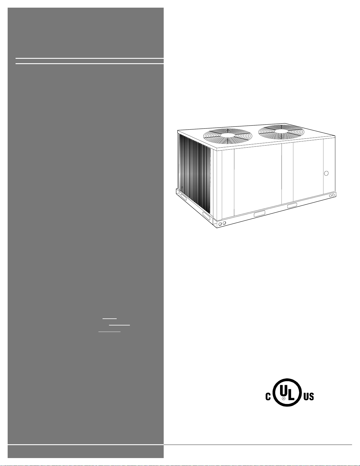
035-18550-001-A-0902
2Unitary Products Group
TABLE OF CONTENTS
NOMENCLATURE. . . . . . . . . . . . . . . . . . . . . . . . . . . 3
GENERAL . . . . . . . . . . . . . . . . . . . . . . . . . . . . . . . . . 4
SAFETY CONSIDERATIONS . . . . . . . . . . . . . . . . . . 4
REFERENCE. . . . . . . . . . . . . . . . . . . . . . . . . . . . . . . . . . .3
AGENCY APPROVALS. . . . . . . . . . . . . . . . . . . . . . . 4
INSPECTION . . . . . . . . . . . . . . . . . . . . . . . . . . . . . . . 4
INSTALLATION. . . . . . . . . . . . . . . . . . . . . . . . . . . . . 5
LIMITATIONS. . . . . . . . . . . . . . . . . . . . . . . . . . . . . . . . . . .5
LOCATION. . . . . . . . . . . . . . . . . . . . . . . . . . . . . . . . . . . . .5
ROOF-TOP LOCATIONS. . . . . . . . . . . . . . . . . . . . . . . . . . . . . .6
GROUND LEVEL LOCATIONS . . . . . . . . . . . . . . . . . . . . . . . . .6
RIGGING AND HANDLING . . . . . . . . . . . . . . . . . . . . . . . .6
CLEARANCES. . . . . . . . . . . . . . . . . . . . . . . . . . . . . . . . . .8
COMPRESSORS. . . . . . . . . . . . . . . . . . . . . . . . . . . . . . . .9
COMPRESSOR CRANKCASE HEATER. . . . . . . . . . . . . . . . . .9
POWER AND CONTROL WIRING . . . . . . . . . . . . . . . . . .9
POWER WIRING . . . . . . . . . . . . . . . . . . . . . . . . . . . . . . . . . . . .9
PHASING . . . . . . . . . . . . . . . . . . . . . . . . . . . . . . . . . . . . . . . . . .9
CONTROL WIRING . . . . . . . . . . . . . . . . . . . . . . . . . . . . . . . . . .9
WIRE SIZING . . . . . . . . . . . . . . . . . . . . . . . . . . . . . . . . . . . . . . .9
REFRIGERANT PIPING . . . . . . . . . . . . . . . . . . . . . . . . .11
GENERAL GUIDELINES . . . . . . . . . . . . . . . . . . . . . . . . . . . . .11
LINE SIZING. . . . . . . . . . . . . . . . . . . . . . . . . . . . . . . . . . . . . . .11
SERVICE VALVES. . . . . . . . . . . . . . . . . . . . . . . . . . . . . . . . . .12
EXTENDING THE SERVICE PORTS . . . . . . . . . . . . . . .13
INSTALLATION . . . . . . . . . . . . . . . . . . . . . . . . . . . . . . . . . . . .13
EVACUATING AND CHARGING. . . . . . . . . . . . . . . . . . .15
ALTERNATE CHARGING METHODS . . . . . . . . . . . . . . . . . . .16
BALANCE POINT SETTING . . . . . . . . . . . . . . . . . . . . . .16
START-UP . . . . . . . . . . . . . . . . . . . . . . . . . . . . . . . . 17
CRANKCASE HEATER. . . . . . . . . . . . . . . . . . . . . . . . . .17
PRE-START CHECK. . . . . . . . . . . . . . . . . . . . . . . . . . . .17
INITIAL START-UP . . . . . . . . . . . . . . . . . . . . . . . . . . . . .18
PHASING. . . . . . . . . . . . . . . . . . . . . . . . . . . . . . . . . . . . .18
OPERATION . . . . . . . . . . . . . . . . . . . . . . . . . . . . . . 18
GENERAL . . . . . . . . . . . . . . . . . . . . . . . . . . . . . . . . . . . . 18
SYSTEM SEQUENCE OF OPERATION. . . . . . . . . . . . . 18
COOLING OPERATION . . . . . . . . . . . . . . . . . . . . . . . . . . . . . 18
HEATING OPERATION . . . . . . . . . . . . . . . . . . . . . . . . . . . . . 19
DEFROST CYCLE . . . . . . . . . . . . . . . . . . . . . . . . . . . . . . . . . 20
OPERATION BELOW 0ºF OUTDOOR TEMPERATURE. . . . 20
EMERGENCY HEAT OPERATION . . . . . . . . . . . . . . . . . . . . 20
SAFETY FEATURES. . . . . . . . . . . . . . . . . . . . . . . . . . . . 20
SECURE OWNER’S APPROVAL . . . . . . . . . . . . . . . . . . 21
MAINTENANCE. . . . . . . . . . . . . . . . . . . . . . . . . . . . 21
CLEANING . . . . . . . . . . . . . . . . . . . . . . . . . . . . . . . . . . . 21
LUBRICATION. . . . . . . . . . . . . . . . . . . . . . . . . . . . . . . . . 21
REPLACEMENT PARTS. . . . . . . . . . . . . . . . . . . . . . . . . 21
NOTICE TO OWNER . . . . . . . . . . . . . . . . . . . . . . . . . . . 21
LIST OF FIGURES
Fig. # Pg. #
1 CENTER OF GRAVITY . . . . . . . . . . . . . . . . . . . . . . . . 6
2 TYPICAL RIGGING . . . . . . . . . . . . . . . . . . . . . . . . . . . 7
3 POINT LOADS. . . . . . . . . . . . . . . . . . . . . . . . . . . . . . . 7
4 UNIT DIMENSIONS AND CLEARANCES. . . . . . . . . . 8
5 TYPICAL FIELD WIRING . . . . . . . . . . . . . . . . . . . . . 10
6 FIELD PIPING DIAGRAMS . . . . . . . . . . . . . . . . . . . . 12
7 EXTENDING THE SERVICE PORTS . . . . . . . . . . . . 15
8 REFRIGERANT FLOW DIAGRAM . . . . . . . . . . . . . . 15
9 CHARGING CURVE EF-10
(COOLING MODE) . . . . . . . . . . . . . . . . . . . . . . . . . . 17
LIST OF TABLES
Tbl. # Pg. #
1 PHYSICAL DATA. . . . . . . . . . . . . . . . . . . . . . . . . . . . . 5
2 UNIT APPLICATION DATA. . . . . . . . . . . . . . . . . . . . . 5
3 ELECTRICAL DATA . . . . . . . . . . . . . . . . . . . . . . . . . 10
4 LIQUID LINES . . . . . . . . . . . . . . . . . . . . . . . . . . . . . . 11
5 VAPOR LINES. . . . . . . . . . . . . . . . . . . . . . . . . . . . . . 12
6 REFRIGERANT LINE CHARGE . . . . . . . . . . . . . . . . 12