Unitrol SOFT TOUCH 9381-34WDS/115 User manual
1
SOFT TOUCH for NON-UNITROL
FREQUENCY CONVERTER CONTROLS
9381-34WDS/115, 9381-34WDS/24DC
9381-34YDS/115, 9381-34YDS/24DC
UNITROL ELECTRONICS, INC.
702 LANDWEHR ROAD
NORTHBROOK, IL 60062
847-480-0115
techsupport@unitrol-electronics.com

2

3
Thank you for purchasing this Unitrol SOFT
TOUCH system. It is designed to protect your
resistance welder operator from serious elec-
trode pinch point injury.
Having trouble or need answers to your ques-
tions? Unitrol supplies free phone support for
the life of this and all our products.
You can contact us:
By Phone:
Monday - Friday 9:00 - 5:00 CT: 847-480-0115.
By Email:
techsupport@unitrol-electronics.com
By Regular Mail:
Unitrol Electronics, Inc.
Technical Support
702 Landwehr Road
Northbrook, Illinois 60062

4
MODEL NUMBER AND OPTIONS AS CHECKED BELOW
SERIAL NUMBER:
MODEL TYPE VALVE
VOLTAGE
OPTIONS
9181-34BPA
Timed bypass. Includes security lock selec-
tor switch, 2 = LED indicator lights, face-
plate. Closes electrodes under low force,
delays, and brings electrodes to welding
force.
9381-34JB3/PMCO
SOFT TOUCH protecon for the RETRACT
stroke. Supplied to operate PMCO welders
with “li” cylinders. Includes RAM POSI-
TION proximity switch and mounng
bracket
kit. Requires addional eld bracketry to
match welder
9381-34JB3
SOFT TOUCH protecon for RETRACT
stroke on standard cylinders that use for-
ward
pressure to go out of RETRACT. Includes
proximity switch and mounng bracket kit.
Requires addional eld bracketry to
match welder
9381-34F2 FORGE DELAY funcon that connects to
exisng Back Pressure (Bucking Pressure)
regulator.
9181-34LSB
Limit Switch. Allows use of a ram position
or continuity. Includes security lock selec-
tor switch, 2 = LED indicator lights, face-
plate. Does NOT include a proximity switch
or mounting bracket kit. Use with custom-
er-supplied PNP proximity switch.
9181-34LSC
Limit Switch used as a redundancy with
continuity. Always in operation and not
keylock selected. Includes RAM POSITON
proximity switch and mounting bracket kit.
May require additional field bracketry to
match welder. Can be turned off by mov-
ing a jumper on the control board .
9381-34WDS/115 CYLINDER OR DIAPHRAGM
HEAVY WEIGHT RAM 115AC
9381-34WDS/24DC CYLINDER OR DIAPHRAGM
HEAVY WEIGHT RAM 24DC
9381-34YDS/115 CYLINDER OR DIAPHRAGM
LIGHT WEIGHT RAM 115AC
9381-34YDS/24DC CYLINDER OR DIAPHRAGM
LIGHT WEIGHT RAM 24DC

5
WARRANTY
Unitrol Electronics provides a 5-year limited warranty to cover all of this SOFT TOUCH sys-
tem. The warranty periods are determined using the date the new control was originally
shipped from Unitrol Electronics. All warranty coverage is FOB Northbrook. Illinois.
This warranty, except for exclusions shown herein covers the following items:
DURING YEAR #1: All parts (exclusive of fuses) that fail due to manufacturing defects.
Necessary labor to repair control that has failed due to manufacturing defects.
DURING YEAR #2: 80% cost of all parts (exclusive of fuses).
80% cost of necessary labor to repair control that has failed due to manufacturing defects.
DURING YEAR #3: 60% cost of all parts (exclusive of fuses).
60% cost of necessary labor to repair control that has failed due to manufacturing defects.
DURING YEAR #4: 40% cost of all parts (exclusive of fuses).
40% cost of necessary labor to repair control that has failed due to manufacturing defects.
DURING YEAR #5:
20% cost of all parts (exclusive of fuses).
20% cost of necessary labor to repair control that has failed due to manufacturing defects.
EXCLUSIONS TO WARRANTY
Any expense involved with repair of control by other than Unitrol Electronics personnel that
has not been authorized in advance and in writing by an officer of Unitrol Electronics.
All costs for freight, to and from Unitrol Electronics, are excluded from this warranty
All field service labor, travel expense, and field living expenses associated with field service
are excluded from this warranty.
No coverage, parts or labor, is offered for components that have failed on control not being
used as specified in Unitrol Electronics published literature, technical sheets, and this direction
book.
No warranty coverage will be made on controls that are being used contrary to specifications,
that were mechanically or electronically altered by customer or installer, or that were physical-
ly damaged after shipment from Unitrol Electronics.
Damages to a control by lightning, flood, or mechanical damage are excluded from this war-
ranty.
Unitrol Electronics assumes no liability for damage to other equipment or injury to personnel
due to a failure in the Unitrol Electronics control.
Unitrol Electronics shall not be responsible for any consequential damages of whatever kind.
Expenses involving alteration or installation of a Unitrol Electronics control are not covered in
this warranty.
NO OTHER UNITROL ELECTRONICS INC. WARRANTY, WRITTEN OR
IMPLIED, COVERS THIS CONTROL UNLESS IN WRITING AND SIGNED
BY AN OFFICER OF UNITROL ELECTRONICS, INC. PRIOR TO SHIP-
MENT OF PRODUCT.

6
TABLE OF CONTENTS
1VERIFY YOUR SOFT TOUCH SENSOR BOARD IS CORRECT
2HOW SYSTEM OPERATES
3INSTALLATION, 9181-34W HEAVY WEIGHT SERIES
4INSTALLATION OF SCR DRIVER BOARD
5CONNECTING SCR FIRING CABLE
5CONNECTING CONTROL CABLE
6WIRING CONTROL
7INSTALLING SECONDARY CURRENT PICKUP COIL
8CONTROL CABLE WIRING CHART
9HOOKUP FOR 9381-34WDS/115, 9381-34YDS/115
10 HOOKUP FOR 9381-34WDS/24DC, 9381-34YDS/24DC
11 RETRACT OPTION 9381-34JB3/PMCO
13 RETRACT OPTION 9181-34JB3
15 TIMED DELAY OPTION 9181-34BP
16 DEPTH SWITCH OPTION, 9181-34LSA, 9181-34LSB
18 DEPTH SWITCH OPTION 9181-34LSC
19 PNEUMATIC HOOKUP, 9181-34Y LIGHT WEIGHT
20 PNEUMATIC HOOKUP, 9181-34W HEAVY WEIGHT
21 ADJUSTING SOFT TOUCH VALVES
22 SETTING MAXIMUM DETECT TIME SWITCHES, BLANK TIME
23 SETTING AND TESTING ELECTRODE CLOSING FORCE
24 SETTING SYSTEM READING SENSITIVITY
25 START-UP PROCEDURE
26 TROUBLE SHOOTING CHART
29 SETTING SYSTEM READING SENSITIVITY
27 BUCKING PRESSURE OPTION 9181-34F2
28 LED INDICATOR LIGHTS
1
VERIFY YOUR SOFT TOUCH SENSOR BOARD IS CORRECT
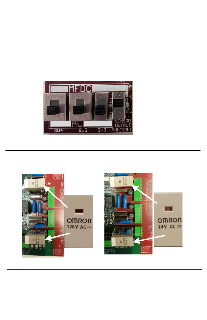
The SOFT TOUCH sensor board can be configured in several ways. Before
turning power on, check to be sure that the mode and valve voltage matches
your welder.
1. TYPE OF WELDING CONTROL. This board can be set to operate various
types of welders. For a Frequency Converter welder, set the four side switches
to the positions shown below.
FOR 115VAC FOR 24VDC
SOLENOID VALVES SOLENOID VALVES
2. SOLENOID VALVE VOLTAGE. Be sure that the two tall relays, K2 and K3,
show the same voltage on the top printing as the solenoid voltage of your
welding control. If they are not correct, contact Unitrol to swap relays.
2
INSTALLATION
Note that this system REPLACES the
existing weld solenoid valve.
1. Mount the control in a convenient location using the four mounting tabs on
the back of the box.
2. Remove hoses from the existing welding solenoid valve. This solenoid valve
will not be used with this this control.
3. Connect hoses from the control to the air cylinder as shown in the photo be-
low.
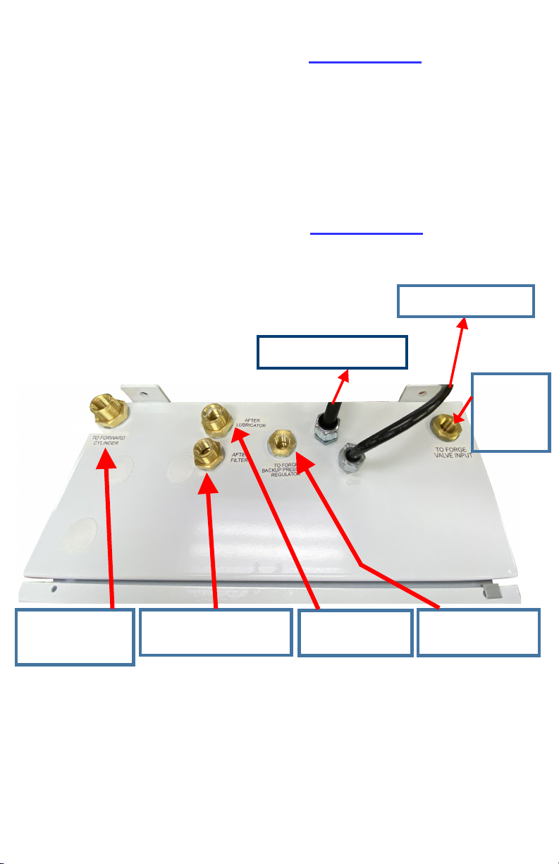
HOSE CONNECTION FOR 9181-34W SERIES CONTROL
Note that this system REPLACES the
existing weld solenoid valve.
Connect to point
aer airline oiler
(weld pressure)
Connect to diaphragm
or air cylinder port that
opens the electrodes.
Connect to point between air
lter/water trap and input to
welding pressure regulator
Connect to diaphragm
or air cylinder port
that closes the elec-
trodes.
TOP OF CABINET
INSTALL FILTERS ON
BOTTOM OF CABINET
TO EXISTING
RETRACT
VALVE INPUT
FOR
9381-34JB
OPTIONS
TO SCR CONTACTORS
TO WELDING CONTROL

3
HOW THE SYSTEM OPERATES
When the solenoid valve output from the welding control
goes HIGH, this voltage goes to the 9280-TS7 SOFT TOUCH de-
tecon board, terminal #9.
The output terminal #11 (SVL) goes HIGH to turn on solenoid
valve SVL . This closes the electrodes under low force.
Relay K2 iniates the SIMPLICITY control on
the door of the cabinet.
Aer the me set on the TRACE DELAY TIME pushwheels (25
cycles is a good starng me), the SIMPLICITY control starts to
re the new SCR contactor into one primary winding of the
welder transformer connuously at very low heat as set on
the TRACE % pushwheels. 1% is normally a good seng. Note
that this delay allows enough me for the electrodes to close
before starng the ow of current to eliminate sparking.
If the electrodes touch the metal being welded, current will
now ow in the welder’s secondary loop and is detected by
the Rogowski secondary current pickup coil connected to the
9280-TS7 board. This will
1. Turn on SVH to put the welding pressure air on the top of
the welder’s diaphragm or cylinder. At the same me, it
starts a me delay of about 0.1 seconds and then turns on
solenoid SVF that switches pressure on the underside of
the diaphragm or piston to back-up pressure.
2. Energizes relay K1 to stop the SIMPLICITY control from r-
ing the SCR contactor.
3. Close the output relay connected to terminals 6-7 on the
9180-TS7 board to close the second stage or pressure
switch input on the welding control to start the welding
procedure.
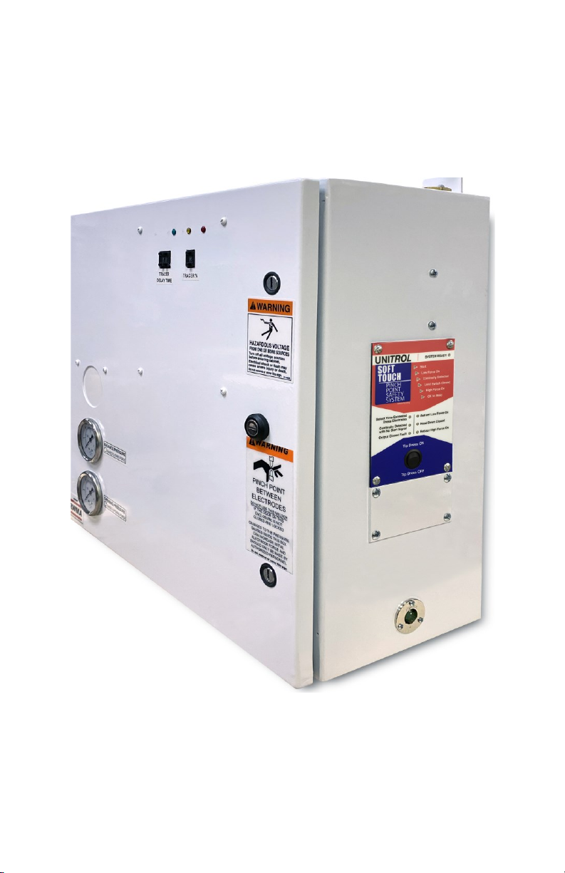
SOFT TOUCH PINCH POINT
PROTECTION SYSTEM
FOR INSTALLATION ON NON-UNITROL
3Ø FREQUENCY CONVERTER CONTROLS
4
INSTALLATION OF SCR DRIVER BOARD
This SOFT TOUCH system is supplied with a separate aluminum heat sink with a
high-voltage SCR contactor installed. The SCR contactor is used to drive the
transformer windings operated by exisng SCR-A during the SOFT TOUCH inial
sequence to produce a TRACE signal as explained on page 3.
Mount this panel, using the screws and nuts provided, in a convenient locaon
inside the welder’s enclosure that houses the three SCR contactors . Locate the
panel as close to the SCR contactor as praccal. Wire it per direcons on page 6.
Drill a 7/8” diameter (1/2” knockout) hole in the welding control cabinet and in-
stall one of the strain relief ngs in this kit with the nut inside the enclosure.
Push the 6-wire cable through this strain relief and ghten the nut. Route the
other end of this cable to the SOFT TOUCH enclosure and install it using the sec-
ond strain relief ng.
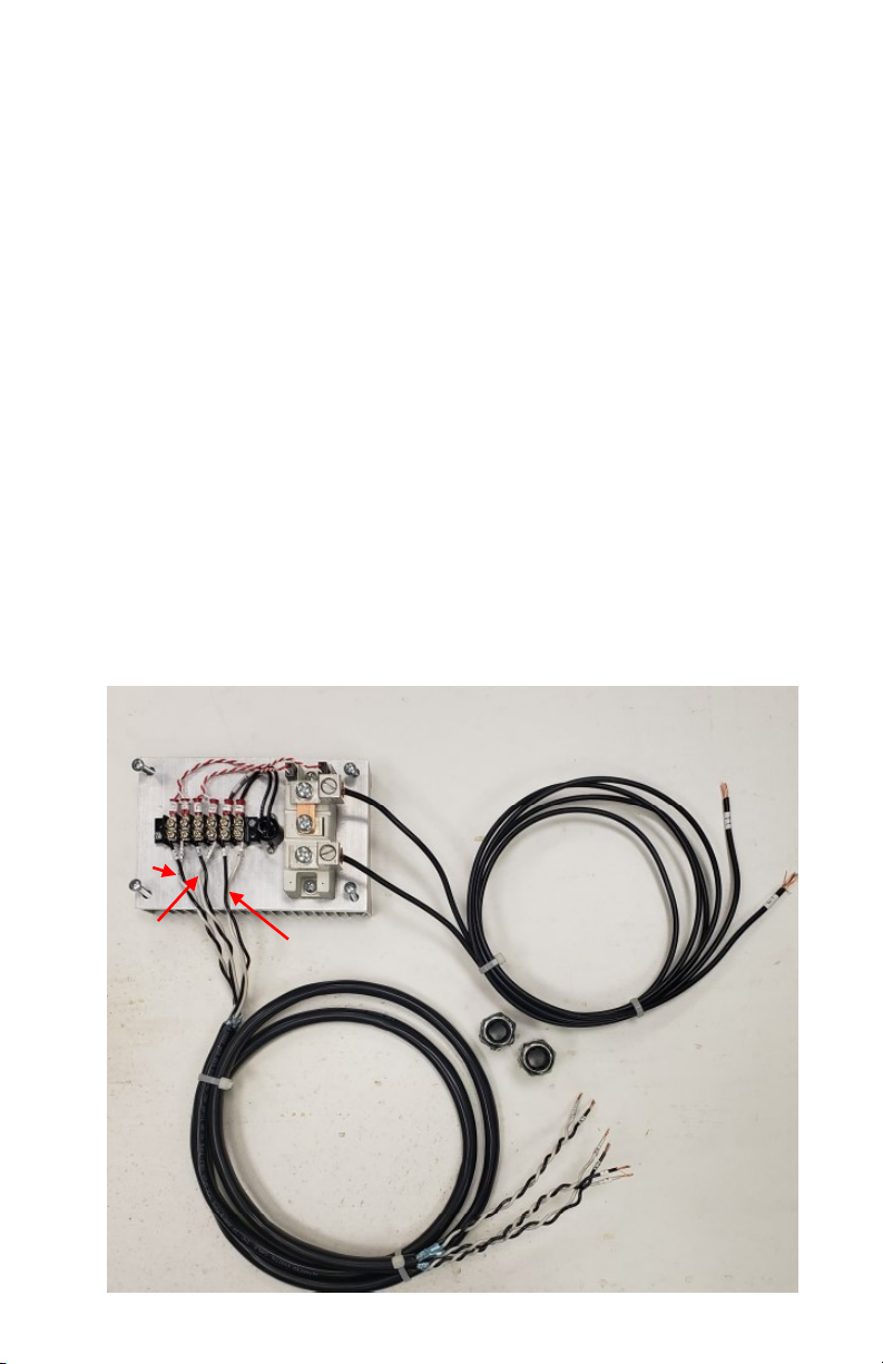
Connect G1/K1 and G2/K2 to these terminals on the SIMPLICITY control.
Connect the third pair to terminals 5 and 6 on the SIMPLICITY control.
CRITICAL: If cable is shortened, check the pairs by looking on
the white wire in each twisted pair for the pair number (1 one,
2 two, 3 three). Double check by verifying connuity on each
pair. Serious damage can occur if the wires are connected to
the wrong terminals.
4
CABLE PAIR 1
CABLE PAIR 2
CABLE PAIR 3
This manual suits for next models
3
Table of contents
Popular Welding System manuals by other brands


TAFA
TAFA 30*8B35 owner's manual

Lincoln Electric
Lincoln Electric INVERTEC V350-PRO CE Technical specifications

ESAB
ESAB Buddy Arc 145 instruction manual

CIGWELD
CIGWELD 636804 use instructions

Red-D-Arc
Red-D-Arc DC-400 Operator's manual

Hobart Welding Products
Hobart Welding Products Spool Gun DP 3035-10 owner's manual


