MCH M1000i User manual


CONTENT
08.Maintenance
1)Change oil
2)Air cleaner service
3)Spark plug service
09.Transporting/Storing
21
21
22
24
25
27
29
30
31
01.Safety information 04
06
08
08
02.Safety label locations
03.Components identification
1)Control Panel
3)RESET
04.Pre-operation check
1)Check oil level
2)Check fuel level
3)Check air cleaner
05.Starting the engine
06.Generator use
4)Oil Warning system
07.Stopping the engine
09
10
10
11
12
13
15
16
18
18
19
20
07
4)Spark arrester maintenance
10.Technical specifications
11.Wiring diagrams
12.Appendix
2)ECON.SW
1)DC application
2)AC application
3)AC Pilot and overload indicator

1.SAFETY INFORMATION
●Read and understand the user manual before
using the generator.
●The emission of engine contains poisonous
carbon monoxide. Use the generator in the
ventilated condition.
●Do not touch the hot muffler, when the
generator is running, or before cooling.
●Gasoline is explosive and flammable in the
specified conditions when refueling, the
generator needs to be stopped and be kept
cigarette and fire source away.
●Do not connect to the building’s electrical
system or other generator, in order to avoid
the electric shocks and fires.
To ensure personal and property safety, please
carefully read the following information.
<<04>>
WARNING
●The running generator must keep one meter
distance with constructions and other
electrical appliances at least.
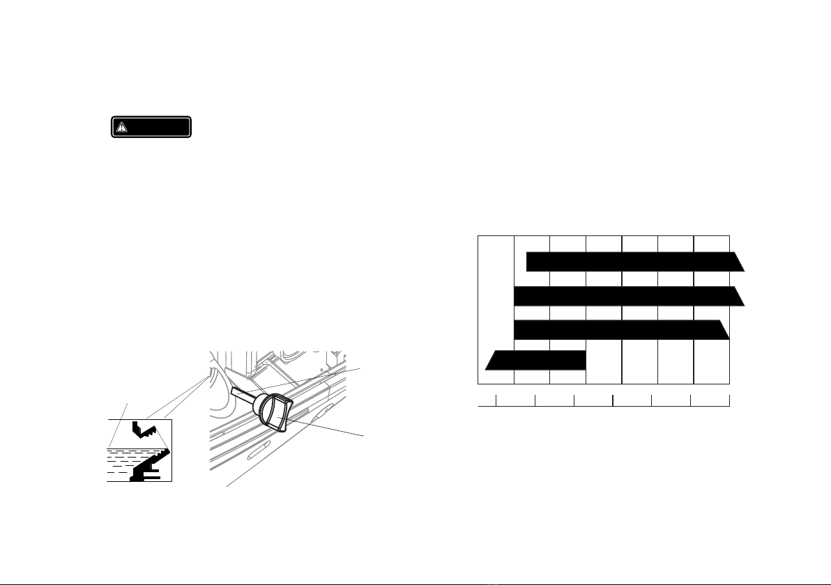
●Place the generator on the leveled surface, in
order to avoid overturning or spilling fuel.
●Children and pets should be keep away the
operation area.
●Do not operate with wet hand.
●Do not expose the generator to rain, moisture
or snow.
●Place the generator at least 1 m away from
buildings or other equipments during
operation.
●The major repair work should be carried out
only by professionally trained person.
●Do not use the generator in underground
working
●Do not use the generator in potentially
explosive atmospheres
●Use personal protective equipment: glove,
mask, earplugs, when you operate or
maintain the generator

<<05>>
SAFETY LABEL:

<<06>>
2. SAFETY LABLE LOCATIONS

<<07>>
3. C IDENTIFICATIONOMPONENTS
CHOKE LEVER
FUEL CAP VENT LEVER
FUEL CAP
LEFT SIDE
MAINTENANCE
COVER
STARTER GRIP
ENGINE SWITCH CONTROL
PANEL
SPARK PLUG
MAINTENANCE
COVER MUFFLER

3.1) Control Panel
1
2
3
4
5
6
7
8
9
<<08>>
3.2) ECON. SW (Economy control switch):
ON
OFF
ONOFF
DC 12V
AC Receptacle
AC Pilot Indicator Light(green)
Overload Indicator Light(red)
Oil warning Indicator Light(red)
Parallel Outlets
Economy Switch
Ground Terminal
USB Outlet
ECON. SW
12
3
4
5
6
7
8
9
•
position, the economy control unit automatically
determines the generator's proper engine speed
based on the connected electronic load. This results
in superior fuel economy and reduces noise.
• When the ECON switch is turned to the "OFF" position,
the engine runs at the rated speed of 4,850 r/min.
Note: The ECON switch must be turned to the "OFF"
position when using electronic devices that require
a large starting current, such as a compressor.
When the Engine ECON switch is turned to the "ON"

●Under the condition of protection,the overload
indicator light(red) is on,the "RESET" button can
recover the output of the generator, and
unnecessary to restart engine overall.
●Press and hold the “RESET” button for one
second, until the overload indicator light (red)
will be off, and output indicator light (green) will
be on.
<<09>>
NOTE
When a high load electrical appliance is
connected instantaneously, in order to reduce
voltage change, turn the economy control
switch to the“OFF”( )position.
In DC operation, turn the economy control
switch to the “OFF”( )position.
Connect both AC load and DC load, turn the
economy control switch to the “OFF”( )
position.
■
■
■
3.3) Reset
NOTE
For protection condition, the output indicator
light (green) is off, and the overload indicator
light (red) is on.
Every starting the engine the " " button is
available within 5 times. Otherwise, you need
restart the engine.
RESET
■
■
“OFF” )
When the economy control switch turns to the “OFF”
( ) engine runs at high speed.
(
●Under the non-overloading condition, the
"RESET" is supposed to be ineffective.

4. PRE- OPERATION CHECK
WARNING
Be sure the generator is on the leveled surface and
the generator is stopped.
Remove the oil filler cap, and then clean it with
cloths. Reinsert it into the crankcase, and take out
to check oil level:
If the oil level reduces at the bottom of the oil filler
cap, add the engine oil.
4.1) Check Oil Level
NOTE
Using non-detergent or 2-stroke oil could
shorten the engine’s working life.
Using the high quality engine oil with strong
detergents
Using 4-stroke engine oil, certified to meet or
exceed API standards: SG, SF ,SAE stickiness
rating:
■
■
■
-30 -20 -10 0 10 20 30 40℃
15W-40
10W-40
10W-30
5W-30
-20 020 40 60 80 100F
NOTE
Carefully use and store the engine oil, avoid
getting dirt or dust into the engine oil.
Mixing different kinds of engine oil is prohibited.
<<10>>
OIL FILLER
CAP
DIPSTICK
Oil Capacity:0.25L
UPPER LEVEL

NOTE
Before the engine oil reduces below the safety
margin, low oil alert system will close the
engine automatically. The oil alert indicator
light ( red) will be on.
To avoid the inconvenience caused by
unexpected stopping, it is still advisable to
check the engine oil level regularly.
Before the engine oil reduces below the safety
margin, low oil alert system will close the
engine automatically. The oil alert indicator
light (red) will be on.
To avoid the inconvenience caused by
unexpected stopping, it is still advisable to
check the engine oil level regularly.
■
■
■
■
4.2) Check Fuel Level
Fuel recommend: use unleaded gasoline (Research
Octane Number of 91 or higher, Pump Octane
Number of 86 or higher).
Never use stale or contaminated gasoline or an
oil/gasoline mixture.
Avoid getting dirt or water into the fuel tank.
Do not use a mixture gasoline containing ethanol or
methanol; otherwise, it will seriously damage the
engine.
Fuel capacity: 2.2L
OPEN
FUEL CAP
UPPER LIMIT MARK
WARNING
●Gasoline is extremely explosive and
flammable.
●Around the refueling area and fuel storage
area, prohibit smoking and firing.
●Do not overfill the fuel tank (no fuel above
the red upper limit mark). After refueling,
make sure the fuel cap is closed properly and
securely.
●Do not make fuel spill from fuel tank. (No
residual fuel around the neck of tank, before
starting engine)
●Avoid contacting with skin or breathing the
fuel vapor.
<<11>>

b.Press the latch tab on the top of the air cleaner.
c.Remove the air cleaner cover.
d.Check the element, clean or replace it, if necessary.
NOTE
Do not run engine without air Cleaner
element, otherwise that makes engine
abrasion.
■
4.3)Check Air Cleaner
Check the air cleaner element to be sure it is clean
and in good condition.
a. Loosen the air cleaner maintenance cover screw,
and remove the cover.
<<12>>
LOWER TAB
AIR CLEANER
COVER
AIR CLEANER ELEMENT
AIR CLEANER BODY
LATCH TAB
LATCH TAB
COVER SCREW
AIR CLEANER MAINTENANCE
COVER

5. STARTING THE ENGINE
NOTE
Before starting engine, disconnect load with AC
receptacle.
Fueling at the first time, refueling, or storing
for a long time, the engine switch should firstly
be opened for ten or twenty seconds and then
require additional pull 10-20 times, in order to
the enough fuel enter into carburetor.
5.1) Turn the fuel cap vent lever to the “ON” position.
■
■
OFF
ON
ON
FUEL CAP VENT LEVER
NOTE
When transporting generator, turn the fuel
cap vent lever to the “OFF” position.
5.2) Turn engine witch to the “ON” position.
■
ON
OFF
ON
E SNGINE WITCH
5.3) Move the choke lever to “CLOSED” position.
CHOKE LEVER
CLOSED
CLOSED
<<13>>

NOTE
Do not move the choke lever to “CLOSED”
position, when engine is hot or ambient
temperature is high.
5.4) Pull the starter grip lightly until you feel
resistance, then pull quickly toward arrow as
shown below.
■
NOTE
Return the starter grip slowly by hand. Do not
make the starter grip spring back quickly.
■
NOTE
If the generator stops and can not restart,
check the oil level firstly.
Carburetor Modification for High Altitude
Operation
At high altitude, the standard carburetor air-fuel
mixture will be too rich. Performance will
decrease, and fuel consumption will increase. A
very rich mixture will also foul the spark plug and
cause hard starting.
If the generator operates at high altitude, change
the main-nozzle or adjust the idling-screw of
carburetor.
■
5.5) After starting and warming up the engine,
turn the choke lever to “OPEN” position.
<<14>>
STARTER GRIP
CHOKE LEVER
OPEN
OPEN

If the generator always operates at altitude
above 1,000 meters, contact with an
authorized dealer servicing to modify the
carburetor.
Generator output power should be modified
according to the altitude and ambient
temperature.The correction factor refers to
13-2.
WARNING
●If the carburetor has been modified for high
altitude operation, the air-fuel mixture will be
too lean for low altitude use. Operation at low
altitude may cause the engine to overheat and
result in serious engine damage. The
carburetor needs return to original
specifications.
6. GENERATOR USE
WARNING
●Be sure to ground the generator when the
connected electrical appliance is grounded.
●Do not connect to the building’s electrical
system, in order to avoid the electric shocks
and fires.
GROUND TERMINAL
<<15>>
EARTH
MARK

NOTE
The AC receptacle can be used while the DC
power is in use. If use both at same time, be
sure not to exceed the total power for AC and
DC. (AC:0.9kVA,DC:5A)
Most of motor appliances require more than
their rated wattage, when starting.
■
■
6.1) DC Application
The DC receptacle, 15-30V under no-load condition,
may be used for charging 12V battery only.
NOTE
In DC operation, turn the ECON.SW to the
"OFF” ( ) position.
6.1.1) Connect the DC receptacle to battery
terminals with the charging cable.
■
WARNING
●For continuous operation, do not exceed the
rated out-put power of generator.
●Do not make parallel connection with other
generators.
●Do not connect an extension to the exhaust
pipe.
●When an extension cable is required, be sure to
use a tough rubber sheathed flexible cable
(according to IEC245 or equivalent standards).
The length of the extension cable: 60m for
2 2
cable of 1.5mm ; 100m for cable of 2.5mm .
●Keep away from other electric cables or wires.
<<16>>
CHARGING CABLE

NOTE
Do not start the automobile engine when the
generator is still connected to the battery,
otherwise the generator will be damaged.
Connect the positive battery terminal to the
positive charging cable. Do not reverse the
charging cable, otherwise generator or battery
will be damaged seriously.
■
■
WARNING
●The battery can release the explosive gases.
Keep the battery away from spark/fire.
Charge the battery in ventilated condition.
●Battery electrolyte contains sulfuric acid that
will cause severe burn of skin and eyes.
Therefore it is necessary to wear the
protective clothing and mask.
●If battery electrolyte gets into eyes, flush
thoroughly with warm water for 15min at
least, and call a doctor immediately.
●If you swallow a little of battery electrolyte
accidentally, flush thoroughly with water your
mouth, and then drink large quantities of
water or milk (with magnesia or vegetable oil),
and call a doctor immediately.
NOTE
The DC receptacle can be used while the AC
power is in use
When DC circuit overload will trip the DC
■
■
●In order to avoid producing the spark at the
terminals of battery, connect the charging
cable firstly to the battery terminals, and then
to the generator. Disconnect the cable firstly at
the generator .
●Before connecting the charging cable to a
battery that is installed in vehicle,the grounded
cable of battery will be disconnected firstly.
This sequence will prevent sparks or short-
circuit. When the cable accidentally contact the
vehicle’s frame or body.
WARNING
<<17>>

6.2) AC applications
6.2.1) Start engine and make sure the output indicator
light (green) is on.
6.2.2) Confirm all electrical appliances are switched
off, and connect the appliance plugs to the
generator receptacle.
NOTE
To obtain the best working and longest working
life of the generator, a new generator is
supposed to run for 20 hours at 50% rated load.
■
OVERLOAD
INDICATOR
LIGHT(RED)
PLUG
NOTE
Confirm all electrical appliances are in good
working condition before connecting them to
the generator. If an electrical appliance
becomes abnormal, sluggish, or stops
suddenly, shut off the generator engine
immediately, and disconnect the appliance.
■
6.3) AC Pilot and Overload Indicator
In normal operating, indicator light
(green) will remain on.
If the generator is overload (over 0.9 kVA), or the
connected appliance is short-circuit, the
indicator light (green) is off, and overload
indicator light (red) is on. The AC power will be
switched off, but engine is still running.
AC Pilot
AC Pilot
circuit and
reset the protector after a few minutes.
protector, remove load firstly, then
DC CIRCUIT PROTECTOR
ON OFF
<<18>>
AC PILOT
INDICATOR
LIGHT (GREEN)

6.4) Oil Warning system
The oil warning system is designed to prevent
engine damage caused by an insufficient amount
of oil in the crankcase. Before the oil level in the
crankcase falls below a safe limit, the oil warning
system will automatically shut down the engine
(the engine switch remains in the “ON“position).
If the oil warning system shuts down the
engine,the oil warning indicator light (red) will be
on,check the engine oil level.
OIL WARNING INDICATOR
LIGHT ( RED)
If the overload indicator light (red) is on, disconnect
the electrical appliances firstly, press and hold the
rest button 1s. If the overload indicator light (red) is
OFF and the AC Pilot indicator light (green) is on,
reconnect the electrical appliances. Otherwise stop
the engine and check the generator.
OVERLOAD
INDICATOR
LIGHT(RED)
AC PILOT
INDICATOR
LIGHT (GREEN)
<<19>>

7.3) Turn the fuel cap vent lever to the“OFF” position.
OFF
ON
FUEL CAP VENT LEVER
OFF
NOTE
Be sure the fuel cap vent lever and engine
switch locate the “OFF” position, when
stopping, transporting and storing the
generator.
■
7. STOPPING THE ENGINE
To stop the engine in an
emergency, turn the engine
switch to the “OFF”position.
7.1) Switch off the connected
electrical appliances, and
pull out their plugs.
ON
OFF
E SNGINE WITCH
<<20>>
Table of contents
Popular Welding System manuals by other brands

Magmaweld
Magmaweld RS 350 M - MW user manual

Panasonic
Panasonic YD-630AT operating instructions

Tweco
Tweco Spray Master Series Safety and operating instructions

TOPMAQ
TOPMAQ LGK-80S user manual

Hobart Welding Products
Hobart Welding Products IronMan 250 owner's manual

CELETTE
CELETTE EASY DENT 3000 Original manual

Jackle
Jackle maxiMIG 250 operating manual

Lincoln Electric
Lincoln Electric Fast Mate Guns Series Operator's manual

ESAB
ESAB HandyPlasma 550 Installation, operation and service manual

RedHotDot
RedHotDot MMAX7 instruction manual

Miller
Miller XMT 304 owner's manual

Lincoln Electric
Lincoln Electric OPTIMARC AC/DC 350-TP Operator's manual