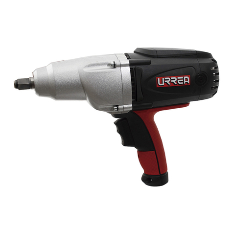
Urrea LI1120 User manual

ATENCIÓN: lea, entienda y siga las instrucciones de seguridad contenidas en este
manual antes de operar esta herramienta.
WARNING: read, understand and follow the safety rules in this manual, before operating this tool.
LI1120 MANUAL DE USUARIO Y
GARANTÍA.
USER’S MANUAL AND WARRANTY.
PISTOLA DE IMPACTO INALÁMBRICA
CORDLESS IMPACT WRENCH

2
General safety rules
Electric safety
Personal safety
Tool use and care
Features
Technical data
Operation instructions
Maintenance
Troubleshooting
Warranty policy
Normas generales de seguridad
Seguridad eléctrica
Seguridad personal
Utilización y cuidados de las
herramientas eléctricas
Características
Especificaciones técnicas
Instrucciones de operación
Mantenimiento
Solucionador de problemas
Garantía
9
9
9
9
10
10
10
13
13
16
3
3
3
4
5
5
5
8
8
16
ENGLISHESPAÑOL
CONTENIDO CONTENT
SÍMBOLOS SYMBOLS
PELIGRO, ADVERTENCIA, PRECAUCIÓN:
Indica un riesgo personal o la posibilidad
de un daño.
Herramientas tipo II: doble aislamiento,
protege las herramientas eléctricas.
Lea el manual de usuario: lea las instruc-
ciones contenidas en este manual.
DANGER, CAUTION, WARNING: indicates risk of
personal injury and/or the possibility of damage.
Type II power tools: indicates double insulation.
Read the user manual: read all the instructions in
this manual.
Utilice protección ocular y equipo de
seguridad recomendado para operar
esta máquina.
Wear eye protection and safety equipment
recommended to operate this machine.

3
ESPAÑOL•Manual de usuario
NORMAS GENERALES DE SEGURIDAD
Esta pistola de impacto inalámbrica tiene ca-
racterísticas que harán su trabajo más rápido y
fácil. Seguridad, comodidad y confiabilidad fue-
ron previstos como prioridad para el diseño del
mismo, haciendo más fácil su operación.
ADVERTENCIA: lea todas las advertencias de
seguridad y todas las instrucciones. La omisión
de alguna de las advertencias e instrucciones
que se enlistan a continuación puede dar como
resultado un choque eléctrico, fuego y/o un da-
ños serios. CONSERVE TODAS LAS ADVERTEN-
CIAS Y TODAS LAS INSTRUCCIONES.
NOTA: la expresión "herramienta" en las adver-
tencias se refiere a la herramienta eléctrica que
se conecta a la fuente de alimentación (con ca-
ble) o a la herramienta que se acciona a batería
(sin cable).
SEGURIDAD EN EL ÁREA DE TRABAJO
Mantenga el área de trabajo limpia y bien ilu-
minada. Las áreas desordenadas y oscuras pro-
vocan accidentes.
No maneje herramientas eléctricas en atmós-
feras explosivas, tales como en presencia de
líquidos inflamables, gases o polvo. Las herra-
mientas eléctricas crean chispas que pueden en-
cender el polvo o los humos.
Mantenga alejados a los niños y curiosos mien-
tras maneja una herramienta eléctrica. Las dis-
tracciones pueden causarle la pérdida del con-
trol.
SEGURIDAD ELÉCTRICA
La clavija de la herramienta eléctrica debe
coincidir con receptáculo. No modificar nunca
la clavija de ninguna manera. No usar ningún
adaptador de clavijas con herramientas eléctri-
cas puestas a tierra. Clavijas no modificadas y
bases coincidentes reducirán el riesgo de cho-
que eléctrico.
Evite el contacto del cuerpo con superficies
puestas a tierra como tuberías, radiadores, co-
cinas eléctricas y refrigeradores. Hay un riesgo
aumentado de choque eléctrico si su cuerpo está
puesto a tierra.
No exponga las herramientas eléctricas a la llu-
via o a condiciones de humedad. El agua que
entre en la herramienta aumentará el riesgo de
choque eléctrico.
No abuse del cable. No usar nunca el cable para
llevar, levantar o desenchufar la herramienta
eléctrica. Mantenga el cable lejos del calor, acei-
te, cantos vivos o piezas en movimiento. Los
cables dañados o enredados aumentan el riesgo
de choque eléctrico.
Cuando maneje una herramienta eléctrica en el
exterior, use una prolongación de cable adecua-
da para uso en el exterior. El uso de una prolon-
gación de cable adecuada para uso en el exte-
rior reduce el riesgo de choque eléctrico.
Si el uso de una herramienta en un lugar hú-
medo es inevitable, use una alimentación pro-
tegida por un dispositivo de corriente residual
(RCD). El uso de un RCD reduce el riesgo de cho-
que eléctrico.
SEGURIDAD PERSONAL
Esté alerta, vigile lo que está haciendo y use el
sentido común cuando maneje una herramien-
ta eléctrica. No use una herramienta eléctrica
cuando esté cansado o bajo la influencia de
drogas, alcohol o medicamentos. Un momento
de distracción mientras maneja herramientas
eléctricas puede causar un daño personal serio.
Use equipo de seguridad. Lleve siempre protec-
ción para los ojos. La utilización para las con-
diciones apropiadas de un equipo de seguridad
tal como mascarilla antipolvo, zapatos no resba-
ladizos, gorro duro, o protección para los oídos
reducirá los daños personales.
Evite un arranque accidental. Asegúrese de que
el interruptor está en posición apagado antes
de conectar a la red y/o a la batería, coger o
transportar la herramienta. Transportar herra-
mientas eléctricas con el dedo sobre el interrup-
tor o enchufar herramientas eléctricas que tie-
nen en interruptor en posición encendido invita
a accidentes.
Retire llaves o herramienta antes de arrancar la
herramienta eléctrica. Una llave o herramienta
dejada unida a una pieza rotativa de una herra-
mienta eléctrica puede causar un daño personal.
No se sobrepase. Mantenga los pies bien asen-
tados sobre el suelo y conserve el equilibrio en
todo momento. Esto permite un mejor control
de la herramienta eléctrica en situaciones ines-
peradas.
Vista adecuadamente. No vista ropa suelta o jo-
yas. Mantenga su pelo, su ropa y guantes aleja-
dos de las piezas en movimiento. La ropa suelta,
las joyas o el pelo largo pueden ser cogidos en
las piezas en movimiento.
Si hay dispositivos para la conexión de medios
de extracción y recolección de polvo, asegúrese
de que éstos estén conectados y se usen correc-
tamente. El uso de estos dispositivos puede re-
ducir los peligros relacionados con el polvo.

4
IMPORTANTE: este aparato no se destina
para utilizarse por personas (incluyendo niños)
cuyas capacidades físicas, sensoriales o mentales
sean diferentes o estén reducidas, o carezcan de
experiencia o conocimiento, a menos que dichas
personas reciban una supervisión o capacitación
para el funcionamiento del aparato por una
persona responsable de su seguridad. Los niños
deben supervisarse para asegurar que ellos no
empleen los aparatos como juguete.
UTILIZACIÓN Y CUIDADOS DE LAS
HERRAMIENTAS ELÉCTRICAS
No fuerce la herramienta eléctrica. Use la he-
rramienta eléctrica correcta para su aplicación.
La herramienta eléctrica correcta hará el traba-
jo mejor y más seguro al ritmo para la que fue
concebida.
No use la herramienta eléctrica si el interruptor
no acciona “encendido” y “apagado”. Cualquier
herramienta eléctrica que no pueda controlarse
con el interruptor es peligrosa y debe repararse.
Desconecte la clavija de la fuente de alimenta-
ción y/o de la batería antes de efectuar cual-
quier ajuste, cambio de accesorios, o de alma-
cenar las herramientas eléctricas. Tales medidas
preventivas de seguridad reducen el riesgo de
arrancar la herramienta accidentalmente.
Almacene las herramientas eléctricas inactivas
fuera del alcance de los niños y no permita el
manejo de la herramienta eléctrica a personas
no familiarizadas con las herramientas o con
estas instrucciones. Las herramientas eléctricas
son peligrosas en manos de usuarios no entre-
nados.
Mantenga las herramientas eléctricas. Com-
pruebe que las partes móviles no estén desa-
lineadas o trabadas, que no haya piezas rotas
u otras condiciones que puedan afectar la ope-
ración de las herramientas eléctricas. Las herra-
mientas eléctricas se reparan antes de su uso,
cuando están dañadas. Muchos accidentes son
causados por herramientas eléctricas pobremen-
te mantenidas.
Mantenga las herramientas de corte afiladas y
limpias. Las herramientas de corte mantenidas
correctamente con los bordes de corte afilados
son menos probables de trabarse y más fáciles
de controlar.
Use la herramienta eléctrica, accesorios y pun-
tas de herramienta, etc. de acuerdo con estas
instrucciones y de la manera prevista para el
tipo particular de herramienta eléctrica, tenien-
do en cuenta las condiciones de trabajo y el tra-
bajo a desarrollar. El uso de la herramienta eléc-
trica para aplicaciones diferentes de las previstas
podría causar una situación de peligro.
SERVICIO: haga revisar su herramienta eléctrica
por un servicio de reparación calificado usando
solamente piezas de reemplazo idénticas. Esto
garantizará que la seguridad de la herramienta
eléctrica se mantiene.
UTILIZACIÓN Y CUIDADOS DE LA HERRAMIEN-
TA A BATERÍA
1.- Recargue únicamente con el cargador especi-
ficado por el fabricante. Un cargador diferente
al especificado podría causar un incendio o da-
ñar la batería.
2.- Use las herramientas solo con paquetes de
batería diseñados específicamente para esa he-
rramienta. El uso de cualquier otro paquete de
batería puede ocasionar un peligro de daños e
incendios.
3.- Cuando la batería no esté en uso, mantenga
lejos de objetos metálicos, como clips, monedas,
llaves, clavos, tornillos o cualquier otro objeto
pequeño de metal que pueda conectar una ter-
minal con otra. Conectar una terminal a otra
puede causar quemaduras e incendios.
4.- Bajo condiciones severas, puede derramarse
líquido de la batería; evite el contacto. Si acci-
dentalmente entra en contacto con el líquido,
lávelo con agua inmediatamente. Si el líquido
toca sus ojos, busque ayuda médica. El líquido
derramado de la batería puede causar irritación
o quemadura.
SERVICIO: haga revisar su herramienta eléctrica
por un servicio de reparación calificado usando
solamente piezas de reemplazo idénticas. Esto
garantizará que la seguridad de la herramienta
eléctrica se mantiene.

5
ESPAÑOL•Manual de usuario
CARACTERÍSTICAS
CONOZCA SU HERRAMIENTA
Antes de intentar usar este producto, familiarí-
cese con todas sus características de operación y
requerimientos de seguridad.
1. Cuadro
2. Luz LED
3. Gatillo con ajuste de velocidad
4. Selector de modo
5. Ventilación
6. Control de avance/reversa
7. Sujetador para cinturón
ESPECIFICACIONES TÉCNICAS
LI1120
CAPACIDAD DEL CUADRO 1/2" (12,7 mm)
BATERÍA 20V
ENTRADA DEL CARGADOR 120V
SALIDA DEL CARGADOR 20V
VELOCIDAD (0-2200) rpm
IMPACTOS POR MINUTO 3000
TORQUE MÁXIMO 170 Nm
PESO 1,5 kg (3,3 lb)
INSTRUCCIONES DE OPERACIÓN
ADVERTENCIA: Si alguna pieza está rota o
faltante, NO intente colocar la batería ni haga
funcionar la herramienta hasta que se reempla-
ce la pieza. De lo contrario, se podrían producir
lesiones graves.
ADVERTENCIA: No intente modificar esta
herramienta ni utilice accesorios no recomenda-
dos para usar con esta herramienta. Cualquier
alteración o modificación de este tipo es un uso
incorrecto y podría provocar una condición peli-
grosa que podría causar lesiones graves.
ADVERTENCIA: su herramienta nunca debe
conectarse a la fuente de alimentación cuando
esté ensamblando objetos, haciendo ajustes,
instalando o retirando cuchillas, limpiando o
cuando no esté en uso. Desconectar la herra-
mienta evitará el arranque accidental, lo que
podría causar lesiones personales graves.
PROCEDIMIENTO PARA COLOCAR LA BATERÍA
(FIG 1)
1. Asegúrese de que
la herramienta esté
apagada.
2. Alinee la nerva-
dura levantada de
la batería con las
ranuras en la parte
inferior de la llave
de impacto, y luego
deslice la batería en
la herramienta.
AVISO: asegúrese de que el pestillo de la batería
encaje en su lugar y que la batería esté asegura-
da a la herramienta antes de la operación.
PARA RETIRAR LA BATERÍA
1. Asegúrese de que la herramienta esté apaga-
da.
2. Presione los botones de liberación de la bate-
ría que se encuentran en la parte frontal de la
batería para liberarla.
3. Jale la batería y extráigala de la herramienta.
GATILLO DE VELOCI-
DAD (FIG 2)
1. Para encender la
Llave de impacto,
presione el gatillo
de velocidad.
2. Para apagarlo, li-
bere el gatillo.
VELOCIDAD VARIABLE
El gatillo de velocidad variable proporciona ma-
yor velocidad cuando incrementa la presión en
el gatillo y menor velocidad cuando disminuye
la presión.
SELECTOR DE DIRECCIÓN DE ROTACIÓN (FIG 3)
La dirección de rotación del cuadro es reversible,
esta es controlada por el selector localizado so-
bre el gatillo de encendido.
Esta llave de impacto no funcionará hasta que
se establezca una dirección de rotación. Soste-
5
6
7
1
3
4
2

6
niendo la llave de
impacto en una posi-
ción normal de ope-
ración:
1. Posicione el se-
lector de dirección
de rotación al lado
izquierdo de la he-
rramienta para di-
rección en sentido
de las manecillas del reloj.
2. Posicione el selector de dirección de rotación
hacia el lado derecho de la herramienta para di-
rección contra de las manecillas.
3. Colocar el selector de dirección de rotación
en la parte central, ayuda a evitar arranques
accidentales cuando la herramienta no está en
operación.
PRECAUCIÓN: Para prevenir daños en los engra-
najes, permita siempre que la llave de impacto
llegue a detenerse completamente antes de
cambiar la dirección de rotación.
SELECTOR DE MODO (FIG 4)
AVISO: la llave de
impacto está diseña-
da con funciones de
3 velocidades y paro
automático, pero las
funciones están dis-
ponibles solo cuan-
do la herramienta
está operando en
rotación en sentido
de las manecillas.
AVISO: el modo solo puede cambiar mientras la
luz indicadora de modo está encendida. La luz
indicadora de modo se apagará automática-
mente después de que haya transcurrido apro-
ximadamente un minuto.
1. Acople la batería a la llave de impacto.
2. Coloque el selector de dirección de rotación a
la izquierda de la herramienta para la rotación
hacia adelante y presione el interruptor de ga-
tillo para encender la luz indicadora de modo.
3. Presione el botón selector de modo; La ve-
locidad cambiará en tres pasos: baja, media y
alta. Mantenga presionado el botón selector de
modo durante tres segundos: el modo de paro
automático está disponible y el indicador de
paro automático estará encendido. Cuando el
perno / tuerca está lo suficientemente apretado,
la herramienta detiene el impacto y la rotación
después de aproximadamente un segundo.
4. Para desactivar la función de paro automáti-
co, mantenga presionado el botón selector de
modo durante tres segundos: el paro automá-
tico se apagará.
FRENO ELÉCTRICO
La llave de impacto está equipada con un freno
eléctrico. Cuando se suelta el interruptor de ga-
tillo, el freno eléctrico se activa automáticamen-
te para detener rápidamente la rotación.
LUZ LED (FIG 5)
La luz de trabajo
LED, ubicada en la
parte frontal de la
llave de impacto, se
iluminará cuando
se presione el inte-
rruptor de gatillo.
Esto proporciona
luz adicional en la
superficie de la pie-
za de trabajo para
operar en áreas de poca luz. La luz se apagará
automáticamente dentro de 10 segundos des-
pués de soltar el gatillo.
CÓMO INSTALAR EL SUJETADOR PARA CINTU-
RÓN (FIG 6)
1. Alinee la nerva-
dura del sujetador
para cinturón con el
orificio en la base de
la llave.
2. Inserte el tornillo
y apriételo firme-
mente con un des-
tornillador (disponi-
ble por separado).
QUITANDO EL SUJETADOR DE CINTURÓN
1. Use un destornillador (disponible por separa-
do) para aflojar el tornillo que mantiene el suje-
tador de cinturón a la llave.
2. Retire el tornillo y el sujetador de cinturón.
INSTALANDO EL
DADO DE IMPACTO
(FIG 7)
AVISO: El anillo de
fricción, con cierta
plasticidad y re-
sistencia, ayuda a
evitar que el dado
de impacto se des-
enganche de la uni-

7
ESPAÑOL•Manual de usuario
dad de salida de la llave de impacto durante la
operación.
Utilice siempre el tamaño correcto de dado de
impacto para tornillos y tuercas. Un dado de im-
pacto incorrecto dará como resultado un par de
aprietes incorrectos e inconsistencia y / o daño
al perno o tuerca.
1. Bloquee el interruptor de gatillo colocando el
selector de dirección de rotación en la posición
OFF (centro).
2. Para instalar el dado de impacto, empújelo en
la unidad de salida de la herramienta hasta que
encaje en su lugar.
3. Para quitar el dado de impacto, simplemente
tire de él.
INSTALACIÓN DE TORNILLOS
AVISO: Mantenga siempre la llave de impacto
en ángulo recto con respecto al sujetador para
evitar dañar el cabezal del tornillo.
Atornillar:
1. Comience a colocando el tornillo con su mano
sobre o dentro de su contraparte roscada (por
ejemplo, una tuerca en el perno, o un perno en
la tuerca o el orificio roscado).
2. Con el dado de impacto adecuado montado
firmemente en la llave de impacto, deslice el
dado de impacto en la tuerca o la cabeza del
perno.
3. Coloque el selector de dirección de rotación
en la posición ADELANTE, y seleccione una ve-
locidad adecuada o la función de parada au-
tomática. Sostenga la herramienta firmemente
mientras presiona el interruptor de gatillo. La
toma de impacto girará el tornillo y la acción de
impacto comenzará cuando el dado de impacto
encuentre resistencia.
Aflojar:
1. Con el dado de impacto adecuado montado
firmemente en la llave, deslice el dado de im-
pacto en la cabeza del perno.
2. Coloque el selector de dirección de rotación
en la posición REVERSA. Sostenga la herramien-
ta firmemente mientras presiona el interruptor
de gatillo. La herramienta comenzará a impac-
tar de inmediato.
3. Una vez que el tornillo se haya "aflojado",
comenzará a desenroscarse. Tenga cuidado de
no permitir que un tornillo gire libremente una
vez que ya no esté enganchado con su contra-
parte roscada, ya que puede ser lanzado fuera
del dado.
CONSEJOS DE IMPACTO
El torque de atornillado adecuado puede diferir
según el tipo o tamaño del perno, el material
de la pieza de trabajo que se va a atornillar, etc.
AVISO: Sostenga la herramienta en línea recta a
lo largo del eje del perno o tuerca.
AVISO: un torque excesivo en el atornillado pue-
de dañar el perno / tuerca o el dado. Antes de
comenzar su trabajo, siempre realice una ope-
ración de prueba para determinar el tiempo de
atornillado adecuado para su perno o tuerca.
Practique con varios dados de impacto, anotan-
do el tiempo requerido para alcanzar el par de
torsión deseado. Si los tornillos están demasiado
estrechos, reduzca el tiempo de impacto. Si no
están lo suficientemente estrechos, aumente el
tiempo de impacto.
OPERACIÓN
Sostenga la herramienta firmemente y coloque
el dado de impacto sobre el perno o tuerca. En-
cienda la herramienta y apriete el perno o tuer-
ca con la torsión adecuada. El torque requerido
para aflojar un tornillo promedia entre el 75%
y el 80% del máximo torque de atornillado, de-
pendiendo de la condición de las superficies de
contacto. Sin embargo, si el óxido o la corrosión
causan que el tornillo se atasque, se puede re-
querir más torque.
Después del atornillado, compruebe siempre el
torque con una llave dinamométrica. El torque
de atornillado se ve afectado por una amplia va-
riedad de factores, incluidos los siguientes:
• Toma de corriente
Si no utiliza el tamaño correcto, el dado causará
una reducción torque de atornillado.
Un enchufe desgastado (desgaste en el extremo
hexagonal o cuadrado) causará una reducción
en el torque.
• Perno
Si bien el coeficiente de torque y la clase de
tornillo pueden ser iguales, el torque de atorni-
llado apropiado diferirá según el diámetro del
tornillo.
Incluso si los diámetros de los pernos son igua-
les, el torque adecuado diferirá según el coefi-
ciente de torque, la clase de perno y la longitud
del perno.
• Accesorios
El uso de una junta universal o una barra de ex-
tensión (ambas disponibles por separado) redu-
cirá un poco la fuerza de atornillado de la llave
de impacto. Compensa atornillando por un pe-
ríodo de tiempo más largo.
• Técnica
La manera de sujetar la herramienta o el mate-
rial a sujetar afectará el torque.
ADVERTENCIA: Siempre use gafas de segu-

8
ridad o anteojos de seguridad con protectores
laterales durante las operaciones con herra-
mientas eléctricas o al soplar el polvo. Si la ope-
ración es polvorienta, también use una máscara
antipolvo.
ADVERTENCIA: No permita que los líquidos
de frenos, gasolina, productos a base de petró-
leo, aceites penetrantes, etc. entren en contac-
to con piezas de plástico en ningún momento.
Los productos químicos pueden dañar, debilitar
o destruir el plástico, lo que puede resultar en
lesiones personales graves.
MANTENIMIENTO
ADVERTENCIA: Asegúrese de desconectar
los enchufes de la fuente de poder, apagar la
máquina y quitar la batería de la herramienta
cuando realice mantenimiento al rotomartillo a
batería y al cargador.
Verifique regularmente que todos los tornillos
se encuentren ajustados. Durante la operación
ocurre una vibración que podría aflojarlos.
Mantenga las ranuras de ventilación limpios y
libres de polvo y obstrucciones. Cuide que no
haya polvo u objetos extraños en las ranuras de
ventilación o al rededor del interruptor.
Utilice un cepillo suave para remover el polvo
acumulado. Use lentes de seguridad cuando rea-
lice la limpieza.
Si el cuerpo de la herramienta necesita limpieza,
limpielo con un trapo suave y húmedo. Puede
usar un detergente suave, pero trate de no uti-
lizar limpiadores con base de alcohol, gasolina u
otros tipos de agentes limpiadores.
ADVERTENCIA: Por ningún motivo deje que
la herramienta entre en contacto con el agua.
¿QUE HACER CON UNA BATERÍA GASTADA?
Para preservar los recursos naturales, recicle o
deshágase apropiadamente de la batería. La
batería de esta herramienta contiene LitioIon.
Consulte las autoridades correspondientes para
obtener información y así poder reciclar o des-
hacerse de la batería.
Descargue completamente la batería operando
su herramienta, remuévala del aparato y cubra
las terminales de la batería con cinta de uso pe-
sado para prevenir un corto circuito.
IMPORTANTE: No trate de abrirlo ni de qui-
tar ningún componente de la herramienta.
SOLUCIONADOR DE PROBLEMAS
PROBLEMA CAUSA SOLUCIÓN
La llave de
impacto no
funciona.
La batería está
agotada.
Cargue la
batería.
La llave de
impacto no
funciona y la
luz LED de la
herramienta
flashea
La herramienta está
sobrecalentada.
Permita
que la
herramienta
se enfríe.
La llave de
impacto no
funciona y
la luz LED
de la batería
flashea.
La batería está sobre-
calentada.
Permita que
la batería se
enfríe.

9
ENGLISH•User's Manual
GENERAL SAFETY RULES
Your Cordless impact wrench NAME has many
features that will make your job faster and
easier. Safety, performance and reliability have
been given top priority in the design of this tool,
qualities to make easy to maintain and to oper-
ate.
WARNING: read and understand all instruc-
tions. Failure to follow all indications listed be-
low, may result in electric shock, fire and/or seri-
ous personal injury.
SAVE THESE INSTRUCTIONS.
SAFETY IN WORKING AREA
Keep your work area clean and well lit. Clut-
tered benches and dark areas may cause acci-
dents.
Do not operate power tools in explosive atmo-
spheres, such as in the presence of flammable
liquids, gases or dust. Some power tools create
sparks which may provoke fire.
Keep away observers, children and visitors
while operating a power tool. Distractions can
cause you to lose control.
ELECTRIC SAFETY
Double insulation eliminates the need for the
three wire grounded power cord and grounded
power supply system.
Avoid the body contact with grounded surfaces
such as pipes, radiators and refrigerators. There
is an increased risk of electric shock if your body
is grounded.
Don’t expose power tools to rain or wet condi-
tions. The presence of water into power tools
will increase the risk of electric shock.
Do not abuse of the power cord. Never use the
power cord to carry the tool and do not pull
the plug off the outlet. Keep the cable away of
heat, oil, sharp edges or moving parts. Replace
damaged cords immediately. Damaged cords in-
crease the risk of electric shock.
When operating a power tool outside, use an
outdoor extension cord marked “W-A” or “W”.
These cords are rated for outdoor use and re-
duce the risk of electric shock.
PERSONAL SAFETY
Stay alert, watch what you are doing and use
common sense when operating a power tool.
Don't use the tool if you are tired or under the
influence of drugs, alcohol or medication. A
moment of inattention while operating power
tools may cause a serious personal injury.
Dress properly. Do not wear loose clothing or
jewelry. Contain long hair. Keep your hair, cloth-
ing and gloves away of moving parts. Loose
clothes, jewelry or long hair can be caught in
moving parts.
Avoid an accidental starting. Be sure that the
switch is OFF before plugging in. Carrying tools
with the finger on the switch or plug in the tool
switch in ON may cause accidents.
Remove the adjusting keys or wrenches before
turning the tool on. A wrench or a key that is
left close to a rotating part of the tool may pro-
voke a personal injury.
Do not overreach. Keep proper footing and bal-
ance at all times. Proper footing and balance
enables better control of the tools on unexpect-
ed situations.
Use safety equipment. Always wear eye protec-
tion. Dust mask, nonskid safety shoes, hard hat,
or hearing protection must be used for appro-
priate conditions.
Before connecting the tool to a power source
(receptacle, outlet, etc.) be sure that the voltage
supplied is the same as that one specified on
the nameplate of the tool. To use a not specified
voltage may cause a serious injury to the user as
well as damage the tool.
IMPORTANT: this appliance is not intended
for use by persons (including children) with re-
duced physical, sensory or mental capabilities
may be different or reduced, or lack of experi-
ence or knowledge, unless such persons are su-
pervised or trained to operate the product by
a person responsible for their safety. Children
should be supervised to ensure they do not use
the devices as toys.
TOOL USE AND CARE
Do not force the power tool. Use the correct
tool for the application. The correct tool will do
the job better and more safely at the rate that it
was designed to work at.
Do not use tools if switch does not turn it on or
off. Any tool that cannot be controlled with the
switch is dangerous and must be repaired.
Disconnect the plug from the power source be-
fore making any adjustments, changing acces-
sories or storing the tool. This preventive safety
measures reduce the risk of accidental starting
of the tool.
When the power tool is not in use, store it out
of the reach of children, and do not allow in-
dividuals who are not familiar with the power

10
5
6
7
1
3
4
2
tool or these instructions to operate it. Power
tools are dangerous in the hands on untrained
users.
Maintain the power tool. Check for misalign-
ment or binding of moving parts, broken parts,
and any other condition that may affect the
operation of the power tool. If it is damaged,
have it repaired before using. Many accidents
are caused by poorly maintained power tools.
Check for misalignment or bonding of moving
parts, breakage parts, and any other condition
that may affect the tools operation. If you find
a damaged tool, take it to service before use it.
Use only accessories that are recommended by
the manufacturer of your model. Suitable ac-
cessories for one tool, may become hazardous
when are used on another tool.
Keep cutting tools, sharpened and clean. Cut-
ting tools in good condition with sharpened
edges, are less likely to stuck in workpieces or
easier to control.
Is recommendable to use a safety device suit-
able, such a thermal and differential switch
when you are using an electric equipment.
USAGE AND CARE OF BATTERY TOOLS
1.- Recharge only with the charger specified by
the manufacurer. A charger other than the one
specified may cause a fire or damage to the bat-
tery.
2.- Use the tools only with battery packs spe-
cifically designed for that tool. The use of any
other battery pack may create a fire and dam-
age hazard.
3.- When the battery is not in use, keep away
from metal objects such as clips, coins, keys,
nails, screws, or any other small metal object
that can connect one terminal to another. Con-
necting one terminal to another can cause burns
and fires.
4.- Under severe conditions, liquid may spill
from the battery; avoid contact. If you acciden-
tally come in contact with the liquid, wash it off
with water immediately. If the liquid gets into
your eyes, get medical help. Spilled liquid from
the battery can cause irritation or burn.
SERVICE: tool service must be performed only
by qualified repair personnel. Service or main-
tenance performed by unqualified personnel
could result in a risk of injury.
FEATURES
KNOW YOUR TOOL
Before attempting to use this product, become
familiar with all of its operating features and
safety requirements.
1. 1/2 Square driver
2. LED Worklight
3. Trigger Switch
4. Mode Selector
5. Vents
6. Direction of rotation selector
7. Belt Clip
TECHNICAL DATA
LI1120
SQUARE DRIVER 1/2" (12,7 mm)
BATTERY 20V
CHARGER INPUT 120V
CHARGER OUTPUT 20V
SPEED (0-2200) rpm
IMPACTS PER MINUTE 3000
MÁX. TORQUE 170 Nm
WEIGHT 1,5 kg (3,3 lb)
OPERATION INSTRUCTIONS
WARNING: If any part is broken or missing, DO
NOT attempt to attach the battery pack, or op-
erate the tool until the broken or missing part is
replaced. Failure to do so could result in possible
serious injury.
WARNING: Do not attempt to modify this tool
or create accessories not recommended for use
with this tool. Any such alteration or modifica-

11
ENGLISH•User's Manual
tion is misuse and could result in a hazardous
condition leading to possibly serious injury.
WARNING: Your tool should never be connected
to the power source when you are assembling
parts, making adjustments, installing or remov-
ing blades, cleaning, or when it is not in use.
Disconnecting the tool will prevent accidental
starting, which could cause serious personal
injury.
UNPACKING
1. Carefully remove the tool and any accessories
from the carton. Make sure that all items listed
in the packing list are included.
2. Inspect the tool carefully to make sure that no
breakage or damage occurred during shipping.
3. Do not discard the packing material until you
have carefully inspected and satisfactorily oper-
ated the tool.
TO ATTACH BATTERY PACK (FIG. 1)
1. Make sure that the tool is switched off.
2. Align the raised rib on the battery pack with
the grooves on the bottom of the
Impact Wrench, and then slide the battery pack
onto the tool.
NOTICE: Make sure that the latch on the battery
pack snaps into place and the battery pack is
secured to the tool before operation.
TO DETACH BATTERY PACK (FIG. 1)
1. Make sure that
the tool is turned
off.
2. Depress the bat-
tery release buttons
located on the front
of the battery pack
to release the bat-
tery pack.
3. Pull the battery
pack out and remove it from the tool.
TRIGGER SWITCH (FIG. 2)
1. To turn the Im-
pact Wrench on,
depress the trigger
switch.
2. To turn it off,
release the trigger
switch.
VARIABLE SPEED
The variable-speed
trigger switch deliv-
ers higher speed with increased trigger pressure
and lower speed with decreased trigger pres-
sure.
DIRECTION -OF-ROTATION SELECTOR (FOR-
WARD/CENTERLOCK/REVERSE) (FIG. 3)
The direction of ro-
tation is reversible
and is controlled by
a selector located
above the trigger
switch. With the
Impact Wrench held
in normal operating
position: Position
the direction-of-
rotation selector
to the left of the tool for forward rotation.
Position the direction-of-rotation selector to the
right of the tool for reverse rotation. Setting the
switch in the OFF (center-lock) position helps
to reduce the possibility of accidental starting
when not in use.
NOTICE: To prevent gear damage, always allow
the Impact Wrench to come to a complete stop
before changing the direction of rotation.
NOTICE: The Impact Wrench will not run unless
the direction of the rotation selector is engaged
fully to the left or right.
MODE SELECTOR (FIG. 4)
NOTICE: The Impact
Wrench is designed
with 3-speed and
auto-stop functions,
but the functions
are available only
when the tool is op-
erating in forward
rotation.
NOTICE: The mode
can change only
while the mode-indicator light is on. The mode
indicator light will be off automatically after ap-
proximately one minute has elapsed.
1. Attach the battery pack to the Impact
Wrench.
2. Position the direction-of-rotation selector to
the left of the tool for forward rotation, and
press the trigger switch to turn on the mode-
indicator light.
3. Press the mode-selector button; the speed will
change in three steps: low, medium and high.
Press and hold the mode-selector button for
three seconds: the auto-stop mode is available
and the auto-stop indicator will be on. When

12
the bolt/nut is sufficiently tight, the tool stops
the impact and rotation after approximately
one second.
4. To turn off the auto-stop function, press and
hold the mode-selector button for three sec-
onds: the auto-stop will turn off.
ELECTRIC BRAKE
The Impact Wrench is equipped with an electric
brake. When the trigger switch is released, the
electric brake engages automatically to quickly
stop the rotation.
LED WORKLIGHT (FIG. 5)
The LED worklight,
located on the
base of the Impact
Wrench, will il-
luminate when
the trigger switch
is depressed. This
provides additional
light on the surface
of the workpiece for
operation in lower-
light areas.
The light will automatically turn off within 10
seconds after releasing the trigger.
INSTALLING THE BELT CLIP (FIG. 6)
1. Align the rib of
the belt clip with
the hole on the base
of the wrench.
2. Insert the screw
and tighten the
screw securely with
a screwdriver (avail-
able separately).
REMOVING THE BELT CLIP
1. Use a screwdriver (available separately) to
loosen the screw that attaches the belt clip to
the wrench.
2. Remove the screw and the belt clip.
INSTALLING AND REMOVING THE SOCKET (FIG.
7)
NOTICE: The friction ring, with certain plasticity
and strength, helps to prevent the socket from
disengaging from the output drive of the im-
pact wrench during the operation.
Always use the correct size socket for bolts and
nuts. An incorrect socket will result in inaccurate
and inconsistent fastening torque and/or dam-
age to the bolt or
nut.
1. Lock the trigger
switch by placing
the direction-of-
rotation selector
in the OFF (center)
position.
2. To install the
socket, push it onto
the output drive of the tool until it locks into
place.
3. To remove the socket, simply pull it off.
INSTALLING FASTENERS
NOTICE: Always keep the Impact Wrench at a
right angle to the fastener to avoid damaging
the fastener head.
To fasten:
1. Start threading the fastener by hand onto
or into its threaded counterpart (e.g. nut onto
bolt, or bolt into nut or threaded hole).
2. With the proper impact socket securely
mounted to the Impact Wrench, slide the impact
socket onto the nut or bolt head.
3. Place the direction-of-rotation selector in the
FORWARD position, and select
a suitable speed or the auto-stop function. Hold
the tool firmly while depressing the trigger
switch. The impact socket will turn the fastener
and the impacting action will begin when the
fastener encounters resistance.
To loosen:
1. With the proper impact socket securely
mounted to the wrench, slide the impact socket
onto the bolt head.
2. Place the direction-of-rotation selector in the
REVERSE position. Hold the tool firmly while
depressing the trigger switch. The tool will start
to impact immediately.
3. Once the fastener has “broken loose,” it will
start to unthread. Be careful that you do not al-
low a fastener to spin freely once it is no longer
engaged with its threaded counterpart, as it
may be thrown out of the socket.
IMPACTING TIPS
The proper fastening torque may differ depend-
ing on the type or size of the bolt, the material
of the workpiece to be fastened, etc.
NOTICE: Hold the tool straight along the axis of
the bolt or nut.
NOTICE: Excessive fastening torque may damage
the bolt/nut or socket. Before starting your job,
always perform a test operation to determine

13
ENGLISH•User's Manual
the proper fastening time for your bolt or nut.
Practice with various fasteners, noting the
length of time required to reach the desired
torque. Check the tightness with a handtorque
wrench. If the fasteners are too tight, reduce the
impacting time. If they are not tight enough,
increase the impacting time.
Hold the tool firmly, and place the socket over
the bolt or nut. Turn the tool on, and fasten the
bolt or nut to the proper torque.
The torque that is required to loosen a fastener
averages 75% to 80% of the tightening torque,
depending on the condition of the contacting
surfaces.
However, if rust or corrosion causes seizing,
more torque may be required.
After fastening, always check the torque with a
torque wrench. The fastening torque is affected
by a wide variety of factors, including the fol-
lowing:
• Socket
Failure to use the correct size socket will cause a
reduction in the fastening torque.
A worn socket (wear on the hex end or square
end) will cause a reduction in the fastening
torque.
• Bolt
Although the torque coefficient and the class
of bolt may be the same, the proper fastening
torque will differ according to the diameter of
the bolt.
Even if the diameters of bolts are the same, the
proper fastening torque will differ according to
the torque coefficient, the class of bolt and the
bolt length.
• Accessories
The use of a universal joint or an extension bar
(both available separately) will reduce the fas-
tening force of the Impact Wrench somewhat.
Compensate by fastening for a longer period of
time.
• Technique
The manner of holding the tool or the material
to be fastened will affect the torque.
WARNING: Always wear safety goggles or
safety glasses with side shields during power
tool operations, or when blowing dust. If opera-
tion is dusty, also wear a dust mask.
WARNING: Do not at any time let brake
fluids, gasoline, petroleum-based products,
penetrating oils, etc. come in contact with
plastic parts. Chemicals can damage, weaken
or destroy plastic, which may result in serious
personal injury.
MAINTENANCE
The tool may be cleaned most effectively with
compressed dry air. Always wear safety goggles
when cleaning tools with compressed air.
Avoid using solvents when cleaning plastic
parts. Most plastics are susceptible to damage
from various types of commercial solvents and
may be damaged by their use.
Use clean clothes to remove dirt, dust, oil,
grease, etc.
BEFORE EACH USE
1. Inspect the Impact Wrench, the on/off switch
and the accessories for damage.
2. Check for damaged, missing, or worn parts.
3. Check for loose screws, misalignment or bind-
ing of moving parts, or any other condition that
may affect the operation.
4. If abnormal vibration or noise occurs, turn the
tool off immediately and have the problem cor-
rected before further use.
5. Detach the battery from the Impact
Wrench before cleaning or performing any
maintenance. Using compressed air may be the
most effective cleaning method.
Always wear safety goggles when cleaning tools
using compressed air.
LUBRICATION
All of the bearings in this tool are lubricated
with a sufficient amount of high grade lubricant
for the life of the unit under normal conditions.
Therefore, no further lubrication is required.
TROUBLESHOOTING
PROBLEM CAUSE SOLUTION
The Impact
Wrench does
not work.
The battery is depleted. Charge the
battery.
The Impact
Wrench does
not work and
the tool LED
worklight
flashes.
The tool is overheated.
Allow the
tool to cool
down.
The impact
wrench does
not work and
the battery
pack LED light
flashes.
The battery is over-
heated.
Allow the
battery to
cool down.

14
Notas / Notes

15
Manual de usuario • User’s manual
Notas / Notes

16
LI1120
URREA HERRAMIENTAS PROFESIONALES S.A.
DE C.V. Warranties this product for a period of 3
years in its parts, components and manual labour
against any manufacture defect from the purchas-
ing date.
Purchase date: ____/____/____
Product:____________________
Brand:______________________
Model:______________________
______________________________
Distributor seal and signature
Sold and Imported by:
URREA HERRAMIENTAS PROFESIONALES S.A. DE
C.V. Carretera a El Castillo, km 11.5, C.P. 45680,
El Salto, Jalisco, México. R.F.C. UHP900402Q29.
Terms:
In order to make warranty effective you must pres-
ent the product along with the warranty properly
filled and signed to an authorized distributor or
service center.
Present the invoice or ticket with official registra-
tion info of the trade from where the product was
purchased. The guarantee is effective as of the date
of purchase stated on the invoice or ticket; or with
the distributor’s stamp (with delivery date in this
policy).
URREA HERRAMIENTAS PROFESIONALES S.A.
DE C.V. Will cover the transportation cost related
to the warranty.
This warranty is not applicable in the follow-
ing cases:
· When the product has not been used according to
normal conditions or natural wear of its parts.
· When the product has not been used according
with this user’s manual instructions.
· When the product has been fixed or modified by
unauthorized or unqualified person.
URREA HERRAMIENTAS PROFESIONALES S.A.
DE C.V. garantiza este producto por el termino de
3 años en sus piezas, componentes y mano de obra
contra cualquier defecto de fabricación a partir de
la fecha de entrega.
Fecha de venta: ____/____/____
Producto: ___________________
Marca: ______________________
Modelo: ____________________
______________________________
Sello y firma de distribuidor
Comercializado e Importado por:
URREA HERRAMIENTAS PROFESIONALES S.A. DE
C.V. Carretera a El Castillo, km 11.5, C.P. 45680,
El Salto, Jalisco, México. R.F.C. UHP900402Q29.
Condiciones:
Para hacer efectiva la garantía deberá presentar
el producto junto con la póliza de garantía debi-
damente firmada y sellada por el establecimiento
donde la adquirió, en cualquiera de los centros de
servicio autorizados.
Presentar la factura o ticket con datos fiscales del
comercio de donde se adquirió el producto. La ga-
rantía cuenta a partir de la fecha de la nota o factu-
ra de compra o el sello con fechador del distribuidor
(con fecha de entrega en esta póliza).
Los gastos de transportación que se deriven del
cumplimiento de la garantía serán cubiertos por:
URREA HERRAMIENTAS PROFESIONALES S.A.
DE C.V.
Esta garantía no será valida en los siguientes
casos:
· Cuando el producto haya sido utilizado en condi-
ciones distintas a las normales o al desgaste natural
de sus partes.
· Cuando el producto no haya sido operado de
acuerdo al instructivo de uso que lo acompaña.
· Cuando el producto haya sido alterado o reparado
por personas no autorizadas.
ESPAÑOL
PÓLIZA DE GARANTÍA
ENGLISH
WARRANT POLICY
Table of contents
Languages:
Other Urrea Impact Driver manuals

Urrea
Urrea UP731A Dimensions and installation guide

Urrea
Urrea UP797-6 User manual

Urrea
Urrea UPX731 User manual

Urrea
Urrea UP893A User manual

Urrea
Urrea UP772HA Dimensions and installation guide

Urrea
Urrea UP898-6B Dimensions and installation guide

Urrea
Urrea UP898-6A Dimensions and installation guide

Urrea
Urrea UP734H Dimensions and installation guide

Urrea
Urrea UP722 Dimensions and installation guide

Urrea
Urrea LI812 Dimensions and installation guide