Urrea UPX731 User manual

ATENCIÓN: lea, entienda y siga las instrucciones de seguridad contenidas en este
manual antes de operar esta herramienta.
WARNING: read, understand and follow the safety rules in this manual, before operating this tool.
UPX893
UPX731
UPX731A
UPX776
UPX727
UPX731B
MANUAL DE USUARIO Y
GARANTÍA.
USER’S MANUAL AND WARRANTY.
PISTOLA DE IMPACTO NEUMÁTICA
COMPOSITE
COMPOSITE AIR IMPACT WRENCH

2
NORMAS GENERALES DE SEGURIDAD
Para reducir el riesgo de choque eléctrico, in-
cendio, y lesiones personales, lea todas las
instrucciones de este manual antes de usar la
herramienta.
ADVERTENCIA: Lea todas las advertencias
de seguridad y todas las instrucciones. La omi-
sión de alguna de las advertencias e instruccio-
nes que se enlistan a continuación puede dar
como resultado un choque eléctrico, fuego y/o
un daños serios. CONSERVE TODAS LAS AD-
VERTENCIAS Y TODAS LAS INSTRUCCIONES.
SEGURIDAD EN EL ÁREA DE TRABAJO
Mantenga el área de trabajo limpia y bien ilu-
minada. Las áreas desordenadas y oscuras pro-
vocan accidentes.
Mantenga alejados a los niños y curiosos mien-
tras maneja una herramienta de poder. Las
distracciones pueden causarle la pérdida del
control.
SEGURIDAD PERSONAL
Esté alerta. Observe lo que esté haciendo y uti-
lice el sentido común cuando opere la herra-
mienta. No opere la herramienta cuando esté
cansado o bajo la influencia de alguna droga,
alcohol, o medicamentos. Un momento de
desatención mientras opera la máquina incre-
menta el riesgo de lesiones a personas.
Vista apropiadamente. No use ropa floja o jo-
yería. Mantenga el cabello, la ropa y guantes
lejos de las partes móviles. Ropa floja, joyería o
cabello largo incrementan el riesgo de lesiones
personales como resultado de ser atrapados
por las partes móviles.
Evite el arranque no intencionado. Asegúrese
de que el interruptor de la herramienta está
en la posición de apagado antes de conectar
al suministro de aire. No cargue la herramienta
con su dedo sobre el interruptor o conecte la
herramienta a la fuente de suministro de aire
con el interruptor encendido.
Retire las llaves de ajuste antes de encender
la herramienta. Una herramienta o llave que
se deje puesta en una pieza giratoria de la he-
rramienta aumenta el riesgo de lesiones per-
sonales.
Mantenga la postura y el equilibrio en todo
momento. Un buen apoyo y equilibrio permi-
ten un mejor control de la herramienta en si-
tuaciones inesperadas.
Utilice el equipo de seguridad. Una máscara
anti polvo, zapatos de seguridad con suela an-
tideslizante y un casco deben ser utilizados en
las operaciones en que se requieren.
Siempre use protección ocular. Use gafas de se-
guridad aprobadas por ANSI.
Siempre use protección para los oídos cuando
utilice la herramienta. La exposición prolon-
gada a ruidos de alta intensidad puede causar
pérdida de la audición.
Riesgo de descarga eléctrica. Esta herramienta
no está provista de una superficie de agarre
aislado. El contacto con un cable “energizado”
hará que las partes metálicas expuestas de la
herramienta se energicen, causando una des-
carga al operador.
Evite el contacto corporal con superficies ate-
rrizadas. Existe un mayor riesgo de descarga
eléctrica si su cuerpo está aterrizado.
Examine la pieza de trabajo para evitar el con-
tacto con cables ocultos. Investigue a fondo la
pieza de trabajo por si existieran cables ocultos
en ella antes de realizar el trabajo. El contacto
con cables energizados ocasionaría una des-
carga eléctrica al operador.
USO Y CUIDADO DE LA HERRAMIENTA
1. Utilice abrazaderas u otra forma práctica
para asegurar y sostener la pieza de trabajo en
una plataforma estable. Sujetar la pieza con la
mano o contra el cuerpo es inestable y puede
conducir a la pérdida de control.
2. No fuerce la herramienta. Utilice la herra-
mienta correcta para cada aplicación. La he-
rramienta correcta hará un trabajo mejor y
más seguro a la velocidad para la que la herra-
mienta está diseñada.
3. No utilice la herramienta si el interruptor de
encendido o apagado no funciona. Cualquier
herramienta que no pueda controlarse con el
interruptor es peligrosa y debe ser reparada.
4. Desconecte la herramienta del suministro de
aire antes de realizar ajustes, cambiar acceso-
rios o guardar la herramienta. Estas medidas
de seguridad preventivas reducen el riesgo
de arrancar la herramienta accidentalmente.
Apague y desconecte el suministro de aire, de
manera segura descargue cualquier presión de
aire residual, y suelte el gatillo antes de salir del
área de trabajo.

3
ESPAÑOL•Manual de usuario
5. Guarde la herramienta cuando no se encuen-
tre en uso y manténgala fuera del alcance de
los niños y otras personas no capacitadas. La
herramienta es peligrosa en manos de perso-
nas inexpertas.
6. Verifique la alineación y el movimiento de
las piezas móviles, rotura de piezas y cualquier
otra condición que afecta el funcionamiento
de la herramienta. Si está dañada, aplíquele
el servicio adecuado antes de usarla. Muchos
accidentes son causados por herramientas mal
cuidadas. Existe el riesgo de un estallido si la
herramienta está dañada.
7. Utilice solo accesorios recomendados por el
fabricante para cada modelo especifico de he-
rramienta. El uso de accesorios no establecidos
para su uso con un modelo de herramienta es-
pecifico, incrementa el riesgo de lesiones per-
sonales.
SERVICIO
1. El servicio de la herramienta debe ser reali-
zado únicamente por personal capacitado.
2. Cuando se realice servicio a la máquina, uti-
lice únicamente refacciones idénticas. Utilice
solamente partes autorizadas.
3. Utilice solamente lubricantes proporciona-
dos con la herramienta o aquellos especifica-
dos por el fabricante.
INSTRUCCIONES DE OPERACIÓN
PREVIO AL FUNCIONAMIENTO
La herramienta ha sido diseñada para funcio-
nar manualmente. Siempre se recomienda que,
mientras se esté utilizando la herramienta, los
operadores permanezcan de pie sobre un piso
sólido, en una posición segura con un agarre y
una base firmes.
Utilice un suministro de aire limpio y lubrica-
do que provea a la herramienta una presión
medida de aproximadamente 90 PSI cuando
la herramienta se encuentre funcionando con
la palanca totalmente presionada. No conec-
te la herramienta al sistema de aire sin una
válvula que cierre fácilmente el aire. Se reco-
mienda utilizar un filtro, regulador y lubrica-
dor de aire, ya que este mismo brindará aire
limpio y lubricado en la presión correcta a la
herramienta. Cuando la presión de suministro
exceda el máximo marcado de la herramienta
en cualquiera de los casos, se utilizarán en todo
momento reguladores de presión de aire ade-
cuados mientras la herramienta esté en funcio-
namiento.
IMPORTANTE: Diseñe la línea de suminis-
tro de aire para asegurar la máxima presión de
funcionamiento en la entrada de aire de la he-
rramienta. Vacíe el condensado de las válvulas
en los puntos inferiores de la tubería, filtro de
aire y depósito del compresor de forma diaria.
Instale un cople de seguridad (válvula de co-
rredera) y utilice un dispositivo de retención
de manguera y coples en cualquier unión de
manguera sin amortiguador interno para evi-
tar que la manguera de un latigazo en caso de
que falle o de que se desconecte.
Se recomienda que la presión del aire en la he-
rramienta sea de 90 PSI mientras la herramien-
ta esté funcionando para que no se exceda el
máximo de revoluciones por minuto. Se puede
hacer funcionar la herramienta a menor pre-
sión pero nunca a más de 90 PSI. Si funcionara
con una presión más baja, el rendimiento de la
herramienta.
CONECTANDO AL SUMINISTRO DE AIRE
1. Nunca conecte la herramienta a una fuente
de suministro de aire que exceda la presión es-
pecificada por el proveedor. Sobre presurizar la
herramienta puede causar que estalle, opera-
ción anormal, rompimiento de los componen-
tes de la máquina o graves lesiones personales.
Utilice solamente aire comprimido limpio, seco
y regulado a la presión establecida o dentro del
rango que se establece para la herramienta.
Siempre verifique que el suministro de aire ha
sido ajustado a la presión establecida o dentro
del rango de presión establecido antes de usar
la herramienta.
2. Nunca utilice oxígeno, dióxido de carbono,
gases combustibles ni ningún gas envasado
como una fuente de aire de la herramienta.
Tales gases son capaces de explotar y causar
lesiones graves a personas.
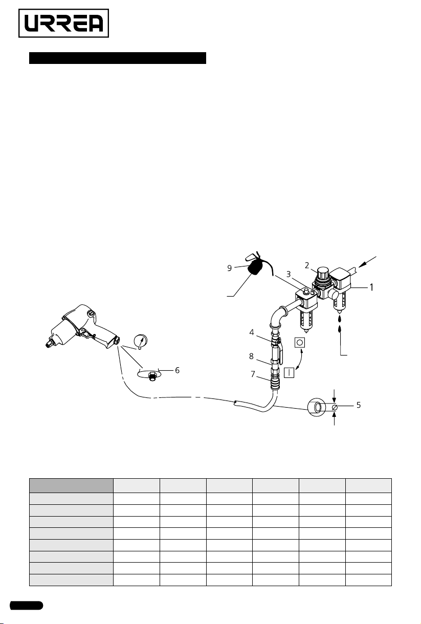
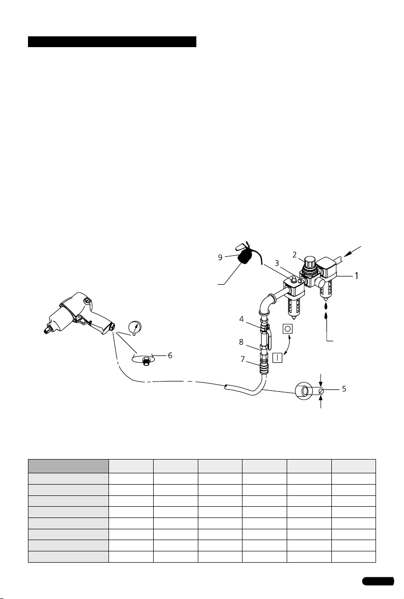
3. Incorpore un filtro, un regulador con manó-
metro, lubricador, válvula de cierre en línea, y
acoplamiento rápido para un mejor servicio,
como se muestra en la siguiente figura. Una
válvula de bola de cierre en línea es un disposi-
tivo importante de seguridad, ya que controla
el suministro de aire, incluso si la manguera de
aire se rompe. La válvula de cierre debe ser una
válvula de bola, ya que se puede cerrar rápi-
damente.

4
MANTENIMIENTO
La frecuencia de mantenimiento debe de ser
de acuerdo a como se muestra en la ilustración
de la siguiente página.
PIEZAS Y MANTENIMIENTO
La reparación y mantenimiento de esta herra-
mienta sólo puede ser llevado a cabo por un
centro de servicio autorizado y su personal ca-
lificado.
Una vez que la vida útil de herramienta se ter-
mine, se recomienda desarmar la herramienta,
desengrasarla y separar las piezas de acuerdo
con el material del que están fabricadas para
su reciclado.
LUBRICACIÓN
Las partes que se muestran en el ensamble de
un buen funcionamiento de su herramienta
neumática se identifican de la siguiente mane-
ra:
1. Filtro de aire.
2. Regulador.
3. Lubricador.
4. Válvula de paso.
5. Diámetro de la manguera.
6. Tamaño de entrada de aire.
7. Válvula de corredera.
8. Cople de seguridad.
9. Aceite.
10. Grasa (Durante el montaje).
24h
48h
90 psi
DATOS TÉCNICOS UPX727 UPX731 UPX731A UPX731B UPX776 UPX893
Tamaño de cuadro
3/8"(9,5 mm) 1/2”(12,7 mm) 1/2”(12,7 mm) 1/2”(12,7 mm) 3/4”(19 mm) 1”(25,4 mm)
Torque máximo
400 ft-lb 1 000 ft-lb 1 000 ft-lb 500 ft-lb 1 400 ft-lb 1 400 ft-lb
Velocidad en vacío
11 000 r/min 7 000 r/min 7 000 r/min 8 000 r/min 5 500 r/min 5 500 r/min
Impactos por minuto
1 600 1 200 1 200 1 200 1 000 1 000
Presión de trabajo
90 PSI 90 PSI 90 PSI 90 PSI 90 PSI 90 PSI
Conexión de entrada
1/4"NPT 1/4"NPT 1/4"NPT 1/4”NPT 3/8"NPT 3/8"NPT
Consumo de aire
4 CFM 4 CFM 4 CFM 5,8 CFM 7 CFM 7 CFM
Peso
1,2 kg (2,6 lb) 1,9 kg (4,18 lb) 2 kg (4,4 lb)
1,11 kg (2,44 lb)
3,4 kg (7,49 lb) 3,5 kg (7,71 lb)

5
ENGLISH•User's Manual
GENERAL SAFETY RULES
To reduce the risks of electric shock, fire, and
injury to persons, read all the instructions be-
fore using the tool.
WARNING: Read and understand all in-
structions. Failure to follow all indications
listed below, may result in electric shock, fire
and/or serious personal injury. SAVE THESE IN-
STRUCTIONS.
WORK AREA SAFETY
Keep the work area clean and well lighted.
Cluttered benches and dark areas increase the
risks of electric shock, fire, and injury to per-
sons.
Do not operate the tool in explosive atmo-
spheres, such as in the presence of flammable
liquids, gases, or dust. The tool is able to cre-
ate sparks resulting in the ignition of the dust
or fumes.
Keep bystanders, children, and visitors away
while operating the tool. Distractions are able
to result in the loss of control of the tool.
PERSONAL SAFETY
Stay alert. Watch what you are doing and use
common sense when operating the tool. Do
not use the tool while tired or under the influ-
ence of drugs, alcohol, or medication. A mo-
ment of inattention while operating the tool
increases the risk of injury to persons.
Dress properly. Do not wear loose clothing or
jewelry. Contain long hair. Keep hair, clothing,
and gloves away from moving parts. Loose
clothes, jewelry, or long hair increases the risk
of injury to persons as a result of being caught
in moving parts.
Avoid unintentional starting. Be sure the
switch is off before connecting to the air sup-
ply. Do not carry the tool with your finger on
the switch or connect the tool to the air supply
with the switch on.
Remove adjusting keys and wrenches before
turning the tool on. A wrench or a key that is
left attached to a rotating part of the tool in-
creases the risk of personal injury.
Keep proper footing and balance at all times.
Proper footing and balance enables better con-
trol of the tool in unexpected situations.
Use safety equipment. A dust mask, non-skid
safety shoes and a hard hat must be used for
the applicable conditions.
Always wear eye protection. Wear ANSI-ap-
proved safety goggles.
Always wear hearing protection when using
the tool. Prolonged exposure to high intensity
noise is able to cause hearing loss.
Risk of Electric Shock. This tool is not provided
with an insulated gripping surface. Contact
with a “live” wire will also make exposed metal
parts of the tool “live” and shock the operator.
Avoid body contact with grounded surfaces.
There is an increased risk of electric shock if
your body is grounded.
Explore the work piece to avoid contact with
hidden wiring. Thoroughly investigate the
work piece for possible hidden wiring before
performing work. Contact with live wiring will
shock the operator.
TOOL USE AND CARE
1. Use clamps or another practical way to se-
cure and support the work piece to a stable
platform. Holding the work by hand or against
the body is unstable and is able to lead to loss
of control.
2. Do not force the tool. Use the correct tool for
the application. The correct tool will do the job
better and safer at the rate for which the tool
is designed.
3. Do not use the tool if the switch does not
turn the tool on or off. Any tool that cannot
be controlled with the switch is dangerous and
must be repaired.
4. Disconnect the tool from the air source be-
fore making any adjustments, changing ac-
cessories, or storing the tool. Such preventive
safety measures reduce the risk of starting
the tool unintentionally. Turn off and detach
the air supply, safely discharge any residual air
pressure, and release the trigger before leav-
ing the work area.
5. Store the tool when it is idle out of reach of
children and other untrained persons. A tool
is dangerous in the hands of untrained users.
6. Check for misalignment or binding of mov-
ing parts, breakage of parts, and any other
condition that affects the tool’s operation. If
damaged, have the tool serviced before using.
Many accidents are caused by poorly main-
tained tools. There is a risk of bursting if the
tool is damaged.
7. Use only accessories that are identified by
the manufacturer for the specific tool model.
Use of an accessory not intended for use with
the specific tool model, increases the risk of in-
jury to persons.

6
SERVICE
1. Tool service must be performed only by qual-
ified repair personnel.
2. When servicing a tool, use only identical re-
placement parts. Use only authorized parts.
3. Use only the lubricants supplied with the
tool or specified by the manufacturer.
OPERATION INSTRUCTIONS
PRIOR THE OPERATION
The tool is intended to be operated as a hand
held tool. It is always recommended that while
using the tool, operators stand on a solid floor,
in a secure position with a firm grip and foot-
ing.
Use a clean lubricated air supply that will give
a measured air pressure at the tool of 90 PSI
when the tool is running with the lever fully
depressed. Do not connect the tool to the air-
line system without an easily accessible air shut
off valve. It is strongly recommended that an
air filter, regulator and lubricator (FRL) be used
as this will supply clean, lubricated air at the
correct pressure to the tool. In any case appro-
priate air pressure regulators shall be used at
all times while operating this tool where the
supply pressure exceeds the marked maximum
of the tool.
Details of such equipment can be obtained for
your tool distributor. If such equipment is not
used, the tool should be manually lubricated.
To manually lubricate the tool, disconnect the
airline and put 2 to 3 drops of suitable pneu-
matic motor lubricating oil into the hose end
(inlet) of the tool. Reconnect tool to the air
supply and run tool slowly for a few seconds to
allow air to circulate the oil. If the tool is used
frequently, lubricate it on a daily basis or lubri-
cate it if the tool starts to slow or lose power.
IMPORTANT: Design the air supply line to
ensure maximum operating pressure in the air
inlet of the tool. Condensation drain valve on
bottom outlets of the pipe, air filter and com-
pressor tank daily.
Install a safety coupling (sliding valve) and use
a hose and couplings restraint in any hose cou-
pling without internal damper to prevent the
hoses whiplash in the event that fails or is dis-
connected.
It is recommended that the air pressure at the
tool be 90 PSI while the tool is running so the
maximum RPM is not exceeded. The tool can be
run at lower pressures but should never be run
higher than 90 PSI. If run at lower pressure the
performance of the tool is reduced.
CONNECTION TO AN AIR SOURCE
1. Never connect to an air source that is ca-
pable of exceeding the pressure specified by
the supplier. Over pressurizing the tool may
cause bursting, abnormal operation, break-
age of the tool or serious injury to persons.
Use only clean, dry, regulated compressed air
at the rated pressure or within the rated pres-
sure range as marked on the tool. Always ver-
ify prior to using the tool that the air source
has been adjusted to the rated air pressure or
within the rated air-pressure range.
2. Never use oxygen, carbon dioxide, combus-
tible gases or any bottled gas as an air source
for the tool. Such gases are capable of explo-
sion and serious injury to persons.
3. Incorporate a filter, regulator with pressure
gauge, oiler, in-line shutoff valve, and quick
coupler for best service, as shown on next
figure. An in-line shutoff ball valve is an im-
portant safety device because it controls the
air supply even if the air hose is ruptured. The
shutoff valve should be a ball valve because it
can be closed quickly.

7
ENGLISH•User's Manual
MAINTENANCE
Maintenance frequency is shown in the illustra-
tion below.
PARTS & MAINTENANCE
Tool repair and maintenance should only be
carried out by an authorized Service Center.
When the life of the tool has expired, it is rec-
ommended that the tool be disassembled, de
greased and parts be separated by material so
that they can be recycled.
LUBRICATION
The parts shown in the assembly for proper
operation of your air tools are identified as fol-
lows:
1. Air filter.
2. Regulator.
3. Lubricator.
4. Emergency shut-off valve.
5. Hose diameter.
6. Thread size.
7. Coupling.
8. Safety Air Fuse.
9. Oil.
10. Grease (During assembly).
24h
48h
90 psi
TECHNICAL DATA UPX727 UPX731 UPX731A UPX731B UPX776 UPX893
Square drive
3/8"(9,5 mm) 1/2”(12,7 mm) 1/2”(12,7 mm) 1/2”(12,7 mm) 3/4”(19 mm) 1”(25,4 mm)
Maximum torque
400 ft-lb 1 000 ft-lb 1 000 ft-lb 500 ft-lb 1 400 ft-lb 1 400 ft-lb
No load speed
11 000 r/min 7 000 r/min 7 000 r/min 8 000 r/min 5 500 r/min 5 500 r/min
Impacts per minute
1 600 1 200 1 200 1 200 1 000 1 000
Working pressure
90 PSI 90 PSI 90 PSI 90 PSI 90 PSI 90 PSI
Air inlet
1/4"NPT 1/4"NPT 1/4"NPT 1/4”NPT 3/8"NPT 3/8"NPT
Air consumption
4 CFM 4 CFM 4 CFM 5,8 CFM 7 CFM 7 CFM
Weight
1,2 kg (2,6 lb) 1,9 kg (4,18 lb) 2 kg (4,4 lb)
1,11 kg (2,44 lb)
3,4 kg (7,49 lb) 3,5 kg (7,71 lb)

8
UPX893 · UPX776
UPX731
UPX731A · UPX731B
UPX727
URREA HERRAMIENTAS PROFESIONALES S.A.
DE C.V. Warranties this product for a period of 1
year in its parts, components and manual labour
against any manufacture defect from the purchas-
ing date.
Purchase date: ____/____/____
Product:____________________
Brand:______________________
Model:______________________
______________________________
Distributor seal and signature
Sold and Imported by:
URREA HERRAMIENTAS PROFESIONALES S.A. DE
C.V. Carretera a El Castillo, km 11.5, C.P. 45680,
El Salto, Jalisco, México. R.F.C. UHP900402Q29.
Terms:
In order to make warranty effective you must pres-
ent the product along with the warranty properly
filled and signed to an authorized distributor or
service center.
Present the invoice or ticket with official registra-
tion info of the trade from where the product was
purchased. The guarantee is effective as of the date
of purchase stated on the invoice or ticket; or with
the distributor’s stamp (with delivery date in this
policy).
URREA HERRAMIENTAS PROFESIONALES S.A.
DE C.V. Will cover the transportation cost related
to the warranty.
This warranty is not applicable in the follow-
ing cases:
· When the product has not been used according to
normal conditions or natural wear of its parts.
· When the product has not been used according
with this user’s manual instructions.
· When the product has been fixed or modified by
unauthorized or unqualified person.
URREA HERRAMIENTAS PROFESIONALES S.A.
DE C.V. garantiza este producto por el termino de
1 año en sus piezas, componentes y mano de obra
contra cualquier defecto de fabricación a partir de
la fecha de entrega.
Fecha de venta: ____/____/____
Producto: ___________________
Marca: ______________________
Modelo: ____________________
______________________________
Sello y firma de distribuidor
Comercializado e Importado por:
URREA HERRAMIENTAS PROFESIONALES S.A. DE
C.V. Carretera a El Castillo, km 11.5, C.P. 45680,
El Salto, Jalisco, México. R.F.C. UHP900402Q29.
Condiciones:
Para hacer efectiva la garantía deberá presentar
el producto junto con la póliza de garantía debi-
damente firmada y sellada por el establecimiento
donde la adquirió, en cualquiera de los centros de
servicio autorizados.
Presentar la factura o ticket con datos fiscales del
comercio de donde se adquirió el producto. La ga-
rantía cuenta a partir de la fecha de la nota o factu-
ra de compra o el sello con fechador del distribuidor
(con fecha de entrega en esta póliza).
Los gastos de transportación que se deriven del
cumplimiento de la garantía serán cubiertos por:
URREA HERRAMIENTAS PROFESIONALES S.A.
DE C.V.
Esta garantía no será valida en los siguientes
casos:
· Cuando el producto haya sido utilizado en condi-
ciones distintas a las normales o al desgaste natural
de sus partes.
· Cuando el producto no haya sido operado de
acuerdo al instructivo de uso que lo acompaña.
· Cuando el producto haya sido alterado o reparado
por personas no autorizadas.
ESPAÑOL
PÓLIZA DE GARANTÍA
ENGLISH
WARRANT POLICY
This manual suits for next models
5
Table of contents
Languages:
Other Urrea Impact Driver manuals

Urrea
Urrea SURTEK PI612 User manual

Urrea
Urrea UP731A Dimensions and installation guide

Urrea
Urrea UP1098-8 Dimensions and installation guide

Urrea
Urrea UP898-6A Dimensions and installation guide

Urrea
Urrea UP893A User manual

Urrea
Urrea UP731 Dimensions and installation guide

Urrea
Urrea UP722 Dimensions and installation guide

Urrea
Urrea UP797-6 User manual

Urrea
Urrea UP734H Dimensions and installation guide

Urrea
Urrea LI812 Dimensions and installation guide