US Blaster USB 7706 Manual

1
USB 7706
Compressor Dual Channel
Many thanks for purchasing this US Blaster product. Always read the safety instructions
below before letting a professional install this equipment.
GENERAL SAFETY INSTRUCTIONS
- Always read the user guide before using the equipment.
- Keep the user guide in a place where everyone can read it.
- Use the equipment indoors and not in a humid rooms.
- Never remove or insert a plug from or into a wall socket with wet hands.
- If the plug and/or cable and/or cable input of the equipment is damaged it must be repaired by
aprofessional.
- Always take the plug out of the wall socket in the event of a thunderstorm, and also when the
equipment is not being used for a while.
- Never remove the plug from the power socket by pulling on its cable.
- Install the equipment in such a way that sufficient cooling is possible.
- Never use the appliance in the vicinity of heat sources and/or in direct sunlight.
- Make sure that no small objects or liquids can get in to the appliance.
- Only clean the appliance with a slightly moist dust-free cloth. Do not use cleaning products or
solutions!
- The appliance contains no components, other than those mentioned in the user guide that can
be repaired or replaced by the user.
- If the appliance is defective, it must be repaired by a US Blaster qualified repairs company.
- Keep the equipment out of reach of children.
Keep the packaging safe so that, if the equipment is defective, you can
send it back in its original packaging and so avoid any damage.
©US Blaster Europe BV
Do not carry out any repairs on the equipment yourself; doing so will invalidate the guarantee.
The equipment may also not be modified; doing so will also invalidate the guarantee.
The guarantee is also invalidated if accidents and damage of any form are caused as a result
of improper use and/or not heeding the warnings in general as laid out in this user guide.
US Blaster Europe accepts no responsibility for any personal accidents as a consequence of not
following the safety instructions and warnings. This is also the case for consequential loss in
any form.

2
USB 7706
Compressor Dual Channel
Features
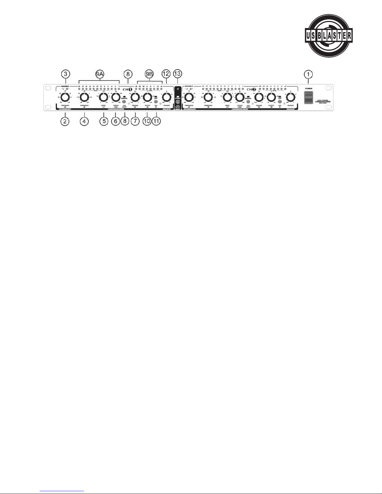
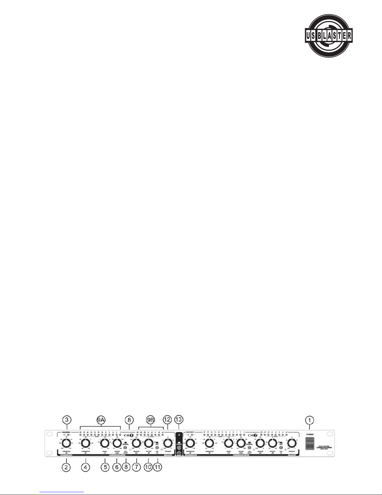
•Two independent compressor/limiter gates in a road-tough steel single-rack-space (1 U) housing.
•Utilizes a unique circuitry which combines hard and soft knee compression styles, thus providing excellent inaudible and
music program compression as well as providing creative and effective dynamics processing
•Advanced operating features include fully automatic or manually variable attack I release times, compression ratio, and
threshold control
•Dual 12 stage gain reduction and 8 stage input output metering
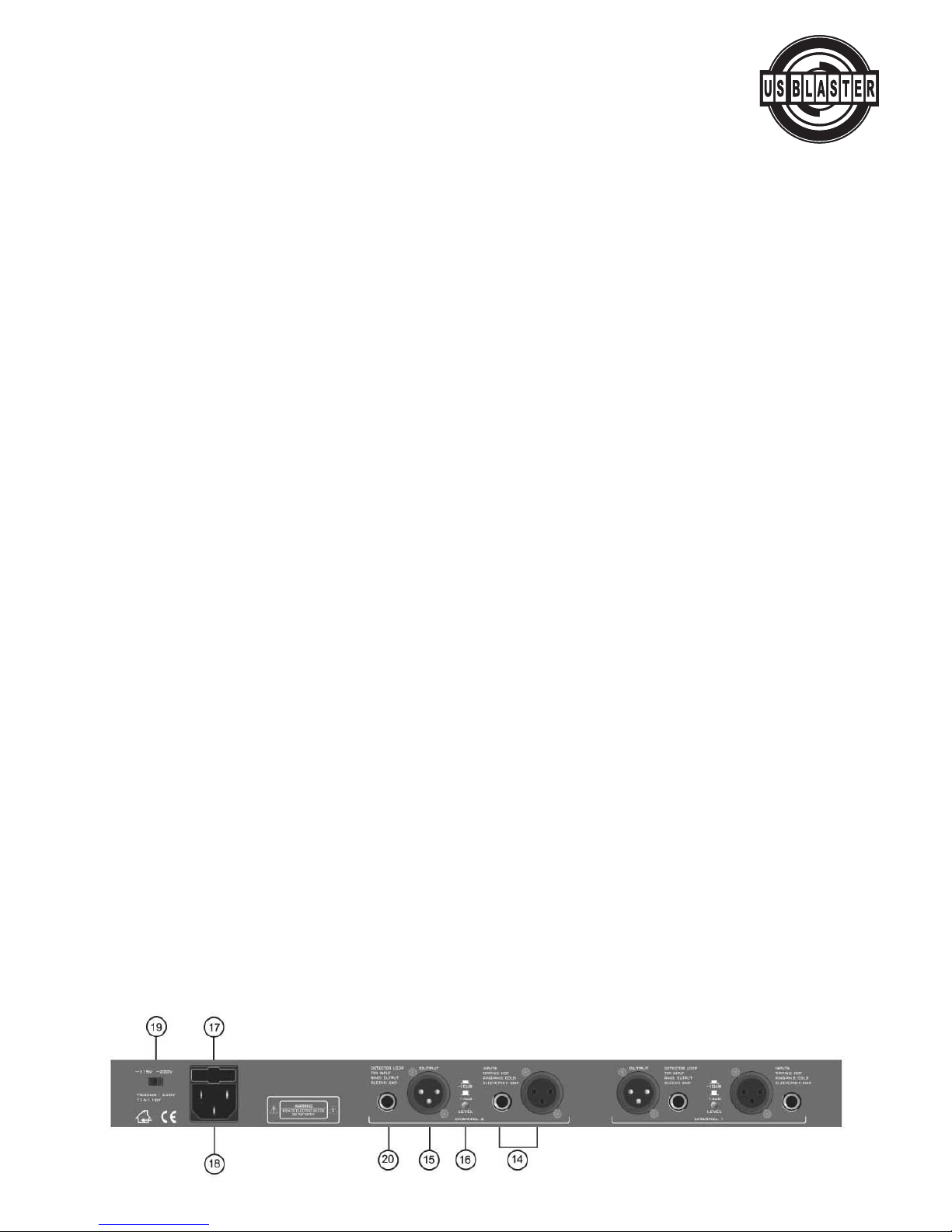
•Dual-mono or stereo operation; servo-balanced inputs (with automatic hum and noise reduction) and outputs
•Built-in adjustable dynamic enhancer (selectively replaces high-end 1055 during even severe compression brought on by
high-energy low-end content)
•IRC (Interactive Ratio Control) expander gate (which automatically adjusts expansion per the program material, thus eli-
minating the noise floor during quiet sections or music pauses)
•TRS side-chain applications, including de-essing, emphasizing de-emphasizing certain instruments during recording, eli-
minating feedback in live applications, and ducking
•Shielded internal power supply and voltage selector for switching between -115VAC (60 Hz)/- 230VACI (50Hz)
INTRODUCTION
The compressor incorporates several new state-of-the-art circuit designs which make it an extremely efficient and univer-
sal dynamics processor: intelligent program recognition, interactive Expander / Gate and a new Dynamic Enhancer.
IKA (Interactive Knee Adaptation) Compressor
The IKA (InteractiveKnee Adaptation) circuitry successfully combines the traditional "Hard Knee" compressor concept
with the "Soft Knee" feature. The "Soft Knee" mode, with its "soft" control characteristics, is the basis of the "inaudible"
and "musical" compression of the program material, while the "Hard Knee" function is a prerequisite both for creative and
efficient dynamics processing and for limiting signal peaks reliably and precisely. This latter function is required to protect
subsequent equipment against distortion, and possible damage.
The Interactive AUTO Processor
The compressor offers an interactive AUTO processor and intelligent program detection. In the AUTO mode, the attack
and release times are derived automatically from the program material, thus effectively eliminating common adjustment
errors. This feature enables optimum results by allowing you to heavily, yet "musically", compress the signals dynamic
range without any audible "pumping ", "breathing" or other side effects.
Manually Adjustable Attack and Release Controls
The response of a compressor and the quality of dynamics processing largely depend on the control times, i.e., the attack
and release functions. When processing signals from individual instruments such as drum, guitar, etc., and when using
the compressor to protect the audio system against signal transients, it is imperative that the control times be user -
adjustable. The compressor offers this feature by providing both ATTACK and RELEASE controls to allow for variable sound
processing.
IRC (Interactive Ratio Control) Expander/gate
Acommon problem in using compressors is that the noise floor can be highly amplified during quiet sections or when
there are music pauses. This effect is exaggerated when the compression ratio is inappropriate. An IRC (Interactive Ratio
Control) Expander/Gate has been integrated into the compressor. The expansion ratio is automatically adjusted, depen-
dent on the program material (The response characteristics of conventional expanders tend to cut into the signal abrupt-
ly,often resulting in unacceptably greater attenuation than desired). With the added IRC, the expander is less critical of
adjustment and more tolerant of useable signals only slightly above the noise floor.
Dynamic Enhancer
One of the most common negativeeffects of compression is the "dulled" or "squashed" sound that is produced when it
is applied to composite music. Since high- energy low frequency instruments cause a compressor to reduce the overall
gain, any high frequency instrument signals occurring simultaneously will also be reduced in level. This "spectral inter
modulation" causes the "squashed" sound effect. The solution to this problem is the Dynamic Enhancer which allows for
selective replacement of high-end 1055accrued through use of compression. Since the Enhancer tracks the amount of
compression, enhancement will not be added when no compression is taking place. No altered sound or any additional
noise. This feature allows you to apply compression throughout the mix without anyadditional outboard enhancer,etc.
The following operational manual will introduce you to the compressor and its various functions.
AFTER READING THE MANUAL CAREFULLY, MAKE SURE IT IS ALWAYS ON HAND FOR FUTURE REFERENCE.
© US Blaster Europe BV

3
USB 7706
Compressor Dual Channel
1.POWER Switch:
This switches the AC power ON or OFF.
Note: In order to avoid possible undesired noise transients in a live sound reinforcement application, switch on the power
to your COMPRESSOR before switching on the amplification system.
Expander/Gate Section (Operation)
Audio, in general, is only as good as the source from which it was derived. The dynamic range of signals will often be res-
tricted by noise. Synthesizers, effects devices, guitar pickups, amplifiers, etc., generally produce a high level of noise, hum
or other ambient background hiss, which can disturb the quality of the program material. Normally these noises are inau-
dible if the level of the desired signal is significantly above the level of the noise. This perception by the ear is based on
the" masking" effect: noise will be masked and thus become inaudible as soon as considerably louder sound signals in
the same frequency band are added. Conversely,the further the level of the desired signal decreases, the more the noise
floor becomes a disturbing factor.
Expanders or noise-gates offer a solution for this problem byattenuating signals when their amplitudes drop,thereby
fading out the background noise. Expanders extend the dynamic range of a signal and are therefore the opposite of com-
pressors. Expansion over the entire dynamic range is not desirable. For example, with an expansion ratio of 5:1 and a
processed dynamic range of 30 dB, an output dynamic range of 150 dB would result, exceeding all subsequent signal pro-
cessors, as well as human hearing. Therefore the amplitude control is restricted to signals whose levels are below a cer-
tain threshold. Signals abovethis threshold pass through the unit unchanged. Due to continuous attenuation of the sig-
nals below this threshold, this kind of expansion is termed "downward" expansion.
The noise-gate is the simplest form of an expander
.In contrast to an expander,which continuously attenuates a signal
below the threshold, the noise gate cuts off the signal abruptly. In most applications this method is not very useful, since
the on/off transition is too drastic. The onset of a simple gate function appears very obvious and unnatural. To achieve an
inaudible processing of the program material, it is necessary to be able to control the signal's envelope parameters.
The COMPRESSOR is equipped with an IRC (Interactive Ratio Control) Expander, so that its expansion ratio is automati-
cally adjusted dependent on the program material. Critical signals in the vicinity of the threshold level are processed with
aminute expansion ratio, whereas signals that reduce in level will be subjected to an increasingly higher ratio, which will
result in greater attenuation. The result is expansion, which is less critical to adjust and more tolerant of useable signals
whose level is only slightly above that of the noise floor. Expansion therefore occurs extremely "50ft" with low ratio set-
tings, while the known negative effects of
expansion are inaudible. The Attack time of the IRC expander is set automatically and program-dependent, i.e., extre-
mely short for quickly changing signals and slower for a more balanced program material. Since the expander/gate adapts
itself automatically to the program material, you will note that the IRC circuit produces considerably better results than
conventional expanders.
2. THRESHOLD Controls:
Use the THRESHOLD controls to determine the threshold point below which expansion occurs. The range of these con-
trols are from OFF to + 10dS.
3. INAUDIBLE Indicators:
For a signal above the threshold value, the "+" LED lights up. For a signal below the threshold, the "-" LED lights up, indi-
cating expansion mode.
© US Blaster Europe BV

4
USB 7706
Compressor Dual Channel
Compressor/Limiter Section (Operation)
Bymeasuring the dynamic range of musical instruments in live recording situations, you will find that extreme amplitudes
will occur which can lead to overload in subsequent signal processing equipment. In most application, these signal peaks
can lead to heavy distortion. To avoid this kind of distortion or, for example, to prevent loudspeakers from being damaged
by overload, compressors or limiters are used. These devices use automatic gain control to reduce the amplitude of loud
passages and therefore restrict the original dynamics to a desired range. This application is particularly useful in micropho-
nerecording to compensate for level changes caused by varying microphone distances. Although compressors and limiters
perform similar tasks, there is one essential difference. Limiters abruptly limit the signal above a certain level while com-
pressors control the signal ~gently" over a wider range. A limiter continuously monitors the signal and intervenes as soon
as an adjustable threshold level is exceeded. Any signal exceeding this threshold will be immediately reduced back to the
adjusted threshold level. A compressor also monitors the program continuously and has a certain threshold level. However,
in contrast to the limiter, signals exceeding the threshold are not reduced abruptly, but gradually. Above the threshold, the
signal is reduced in level relative to the amount the signal exceeds this point. Generally, threshold levels for compressors
are set below the normal operating level to allow for the upper dynamics to be musically compressed. For limiters, the
threshold level is set above the normal operating level in order to provide reliable signal limiting and thus protect subse-
quent equipment.
The extensivecontrols of the Compressor section provide a great range of dynamic effects: from musical and soft com-
pression to limiting signal peaks, right up to extreme and effective compression of the overall dynamics. For example, a
low ratio and very low threshold setting can be used to achieve50ft and musical processing of the general dynamics of the
program material. Higher ratios, together with low threshold settings, create relatively constant volume (leveling) for instru-
ments by preventing the output level from significantly exceeding the threshold point (provided the OUTPUT controls in the
0 dB position). Please note that the compression of the entire program material (achieved by low threshold settings) sounds
less natural with higher ratio settings. Ratio settings in the range of 4:1 and lower affect the dynamics of the program mate-
rial less and are often used to compress the sound of a bass guitar, a snare drum or a vocal. Sensitive and moderate set-
tings are generally used in mixing and for leveling of program material in broadcasting.
In the COMPRESSOR, control of the dynamics process is achieved by means of a high quality VCA (Voltage Controlled
Amplifier) with an operating range of about 60 dB,Le.,the input signal level can be reduced or increased within a range of
60 dB.Input signal levels below the adjusted threshold are not reduced. However, as soon as the input signal exceeds the
threshold level, dynamics control is activated. The amount of compression (gain reduction) is proportional to the amount
bywhich the input signal exceeds the threshold level. With the threshold control completely turned clockwise, the thres-
hold value is +20 dB.Since such a value will not be reached in practice, you can use it to disable the compressor section
and work exclusively either the expander/gate and the dynamic enhancer circuits.
Rotate the THRESHOLD control counterclockwise until an appropriate amount of gain reduction is indicated on the GAIN
REDUCTION meter. This operation will be accompanied by an audible drop in output level. The OUTPUT control should now
be turned clockwise to reinstate the output level. Final adjustments of the controls can then be made to suit your particu-
lar requirements, including the RATIO, ATTACK and RELEASE controls. The AUTO function of the attack and release times
provides program dependent dynamic processing, which suits most standard uses. If a “condensed” or "wider" sound pro-
cessing technique is required, the attack and release times can also be manually adjusted.
The experienced user will be in a position to specify parameters while in bypass mode and thus realize the effect before the
unit is actually switched into operation. This is important in live situations, where a signal needs to be managed efficiently
bythe sound technician, without the convenience of continuous A/B comparison. For using the Compressor/Limiter as a
Limiter,you should set Ratio turned fully clockwise to co:1, switch out the AUTO function and manually adjust short Attack
and maximum Release times. Use the THRESHOLD control to set the threshold for the limiting level.
4. THRESHOLD Controls:
The THRESHOLD controls set the threshold point for the compressor sections. They have a range of -40 to +20 dB.
© US Blaster Europe BV

5
USB 7706
Compressor Dual Channel
5. RATIO Controls:
The RATIO controls determine the ratio between the input and output level for all signals exceeding the threshold point.
The control range can be adjusted from 1:1 to ∞:1. A ratio of 1;1 indicates that the there is no level change between the
input and output. A ratio of 2:1 indicates, that for every 2 dB increase in input level above the threshold, there will be a
corresponding in increase in output level of 1dB. Similarly, a ratio of 10:1 indicates that for every 10dB increase in input
level above the threshold, there will be a corresponding increase in the output level of 1dB. If the RATIO control is set
fully clockwise, this corresponds to a ratio of infinity: 1. This means that all input levels are reduced to the threshold point
and are thus kept constant. (Note: Although a "hard" or infinite ratio limit has applications in certain specialized situati-
ons, in general, this setting is neither appropriate nor necessary as it would cause audible side effects.)
6. ATTACK controls:
The ATTACK controls determine the rate by which the compressors respond to a signal exceeding the threshold. These
controls can be adjusted from 0.1 to 200 milliseconds.
(Note: A short attack time is required for very fast transients (level peaks) such as handclaps, snare drums, etc., so that
the compressor is in a position to regulate these types of peaks. With other kinds of program material, it can be advan-
tageous to apply longer attack times. In fact, it's always recommended to begin processing with longer attack times and
only reduce the times carefully as required, as the danger of dynamic distortion usually increases with shorter attack
times.)
7. RELEASE controls:
The RELEASE controls determine the rate by which the compressors return to unity gain after falling below the threshold
level. These controls can be adjusted from 0.05 to 4 seconds. (Note: The release time is largely dependent on the pro-
gram material. If the time is incorrectly set, this can lead to 2 fundamental problems: (1) If the release time is too short,
the overall volume will fluctuate when signals peak above the threshold level, giving sound an unpleasant pumping effect;
(2) If the release time is too long, pumping and breathing side effects will result when a loud passage is abruptly follo-
wed by a quiet passage.)
8. AUTO Switches:
By activating the AUTOswitches, the ATIACK and RELEASE controls are disabled and the attack and release rates are
automatically derived from the program material by means of intelligent program recognition, so that setting errors can
be effectively avoided. The AUTO processor eliminates side effects such as pumping, modulation distortion, etc., which
are found in conventional compressors. This function allows for unobtrusivemusical compression of signals or mixes with
widely varying dynamics. The settings of the attack and release controls will function only when these switches are set to
MANUAL position.
9a. GAIN REDUCTION Meters:
The 12-segment GAIN REDUCTION meters indicate how effectively the gain is reduced bythe compressor within a range
from 1 to 30 dB. (Note: Although the VCA of the COMPRESSOR features a control range of almost 60 dB, it is not useful
to display the entire range, as in practice, such a broad control range will hardly ever be required. The visual range of the
GAIN REDUCTION meter is thus only 30 dB)
9b. INPUT LEVEL Meters:
The 8-segment INPUT/OUTPUT meters display the input signal levels to the COMPRESSOR when the IN/OUT switch (11)
is in the OUT position (bypass). When the IN/OUT switch is set to IN, the INPUT/OUTPUT meter displays its channel sig-
nal output level.
10. OUTPUT Controls:
The OUTPUT controls allow for the increase or decrease of the output signals bymaximum of 20 dB.This allows compen-
sation for a level 1055 due to the compression or limiting process.
11.IN/OUT Switches:
The IN/OUT Switches activate the corresponding channel. This switch acts as a so-called "hard-bypass" so that when the
switch is OUT, the input jack is directly linked to the output jack. Normally, this switch is used to perform a direct A/B
comparison between the unprocessed and the compressed or limited signals.
© US Blaster Europe BV

6
USB 7706
Compressor Dual Channel
Dynamic Enhancer Section (Operation)
Dynamic enhancement allows for selective replacement of high-end loss accrued through use of compression. As the sig-
nal level rises towards the threshold point where compression will occur, high frequency enhancement is added at the same
degree to which the input signal is compressed. The Compressor/Limiter accurately tracks the amount of compression in
order to compensate with the same amount of dynamic enhancement, even if there are heavy signal variations. When there
is no compression, the signal is not enhanced. For more versatility, a PROCESS control allows you to control the available
amount of dynamic enhancement.
12. PROCESS CONTROL:
The PROCESS control sets the available amount of enhancement on a relative scale between off and 6. Dynamic enhance-
ment allows you to replenish any high frequencies lost through the compression process for absolutely natural sounding
dynamics control. Enhancement is only added when compression is taking place.
13. MODE (STEREOIMONO) Switch:
The MODE switch can be used to select either Stereo of Mono operation as marked. In stereo mode, both channels opera-
te independently and all the separate channel controls are functional for both channels. In the MONO (depressed button)
mode, the controls of Channel 1 take over all the functions of Channel 2 with the exception of the IN/OUT and the PRO-
CESS control of the Dynamic Compressor Limiter.
14. INPUTS:
The COMPRESSOR is equipped with both 1/4" (6.3mm) TRS and XLR audio input jacks. These can be used for either balan-
ced or unbalanced operation as follows:
Unbalanced use of mono 1/4" plugs: Tip = Signal, Sleeve = Ground I Shield.
Balanced use of TRS stereo 1/4" plugs: Tip = hot (+), Ring = cold (-), Sleeve = Ground / Shield.
Balanced use with XLR connectors: 1 = Ground I Shield, 2 = hot (+), 3 = cold (-).
15. 0UTPUTS:
The audio outputs of the COMPRESSOR are XLR connectors.
Balanced XLR connectors: 1 = Ground I Shield, 2 = hot (+), 3 = cold (-).
16. OPERATING LEVEL Switch:
With the OPERATING LEVEL switch, you can select either of 2 operating levels: the - 10 dBV home recording level or the
+4 dBu professional studio level. The level meters are referenced automatically to the selected level so that optimal ope-
rating range of the meters will always be ensured.
17. FUSE HOLDER:
The IEC power socket has an integral fuse holder that takes a 20mm fuse. Always replace a blown fuse with the same type
as specified on the rear of the unit.
18.POWER CONNECTION:
Astandard IEC AC power socket for connecting to the main AC supply with the power cord supplied.
19. AC VOLTAGE SELECTOR Switch:
Use the VOLTAGE SELECTOR Switch to set the unit for the proper voltage for your area, 115 VAC/60 Hz or 230 VAC/50 Hz.
(Note: Selecting the wrong voltage can damage the unit.)
20. DETECTOR LOOP INSERT:
This 1/4" TRS jack can be used as insert point to enable the unit to be controlled externally to operate frequency consci-
ous via an equalizer.You can use the connector as a pure input (mono jack connector) or as an insert (stereo jack connec-
tor). In this case, use a special insert adapter cable, which splits up one stereo into two mono jack connectors. The ring of
the DETECTOR LOOP connector carries the unit's output signal and the tip receives the processed signal from an external
unit.
© US Blaster Europe BV

7
USB 7706
Compressor Dual Channel
APPLICATIONS
Inthis section, several typical applications of the COMPRESSOR are discussed. The following basic settings can resolve
most dynamic problems. They are the ideal starting point. Please take the time to study the application examples care-
fully, in order to be able to make full use of the capabilities of your COMPRESSOR in the future.
1. MAIN APPLICATIONS AND INITIAL SETTINGS
The main applications of the COMPRESSOR can be divided into several categories:
a. The Expander/gate function is used to eliminate interference and to suppress background noise and leakage on indivi-
dual tracks in multi-track recording.
b. The Compressor function is used to compress the program material and to create special effects and unusual sounds,
which are used for recording and musical performance.
c. The Limiter function is designed to protect loudspeakers, tape recorders, transmitters, etc. from signal peaks, sort term
overloading and over modulation (transmitters etc.).
1.1 Compression! Leveling! Limiting/Clipping
Now that the functions and operation of the individual sections and their controls have been explained, we would like to
acquaint you with more of the terms and relationships of the dynamics process.
Compression
Acompressor converts a large dynamic level into a restricted range. The extent of the resulting dynamic level is depen-
dent on the threshold, attack, release and ratio settings. As it is the desired effect of a compressor to increase a low level
signal, generally the threshold is set low. The "inaudible" compression mode requires fast attack and release times and
low ratios. The fastest the chosen control times and the higher the compression ratio, the greater the effect on the short-
term dynamics. This fact is often used to achieveaudible and creativesound effects.
Leveling
The leveling mode is used to keep output level constant, i.e. to compensate for long term gain changes, without affec-
ting the short -term dynamics. Normally, the threshold is set quite low in order to be able to increase low-level signals.
Leveling requires slow attack and release times, combined with a high ratio. Because of the very slow response time, leve-
ling has no effect on signal peaks or short-term changes in average level.
Limiting
The limiting function requires a fast attack time and a high ratio and release time setting, which is dependent on the spe-
cific use and the desired sound effect. As it is usually the task of a limiter to limit only high signal peaks, the threshold is
usually set at a high level. The dynamics are reduced dependent on the ratio setting and the degree by which the thres-
hold point was exceeded. If the attack time is adjusted to control only the average level without affecting signal peaks
above the threshold, this is referred to as the program limiter. For this purpose the attack time will be set above 20 ms.
If the attack time is further reduced in order to also control signal peaks, this is defined as a peak limiter.
Clipping
In contrast to the two previously mentioned limiters, the clipping mode features infinitely fast control times, and infinite
compression ratio and creates an unsurpassable barrier ("brick wall") for all signals above a certain level. To be able to
control the signal peaks, the clipping function radically cuts signals above the threshold, without affecting the amplitude
of the original signal. If used in normal applications, this function remains inaudible and under certain circumstances it
can even lead to an improved sound, because cutting the transients creates artificial harmonics. If misused, clipping can
cause very obvious and distasteful distortion, which when taken to the extreme, will convert the signal's waveform into
asquare wave signal. This effect is often produced in guitar distortion devices ("fuzz boxes").
© US Blaster Europe BV

8
USB 7706
Compressor Dual Channel
2.EXPANDER/GATE SECTION
The main task of the Expander/gate is to "inaudibly" eliminate undesirable background noise from the usable signal. This
assumes that there is a slight level difference between the usable signal and noise floor, in order to be able to define the
operating threshold of the Expander/Gate. At the same time, the Expander/gate must respond very quickly (have a very
fast attack time) so that the signal's leading edge remains unaltered.
Because the Expander/gate of the COMPRESSOR is self-adapting to the program material. it will be possible to obtain more
satisfactory results with the new IRC (Interactive Ratio Control) circuit than with conventional expanders. When expansion
occurs there are no common side effects due to the extremely smooth and unobtrusive action of the circuit.
When the Expander starts to operate, the INAUDIBLE LED INDICATORS will illuminate. For a signal above the threshold
value, the "+" LED lights. The "-" LED lights when expansion occurs. because the expansion initially starts very smoothly.
You may find yourself in a situation where this LED illuminates with little or no perceived gain reduction occurring.
2.1 Controlling Leakage In The Studio
Expander/gates are most commonly used to suppress undesirable leakage of sound from one track to another during recor-
ding or playback. They are usually used when recording drum kits, where the mics are very close to each other. High volu-
me levels of individual instruments often cause considerable leakage onto all the adjacent mics and results in conflicting
frequency and phase coherence problems, as well as unspecified sounds ("comb" filter effects). It is vitally important that
every instrument is recorded into a separate mic and that each mic is individually gated.
Patch the COMPRESSOR into a snare drum channel for example and adjust it so that triggering only occurs on snare hits.
Each mic should be set to its maximum operating level, monitored and the THRESHOLD level set so the each snare hit
sounds acoustically clean and separate, as though it was played on its own.
The optimum use of the Expander/gate depends principally on microphone technique. Be particularly careful, when high
frequency instruments are located to the side or rear of a Cardioid microphone. Most cardioids exhibit a sharply rising off-
axis response characteristic at higher frequencies. If there is only a 2 or 3 dB difference between the on-axis and off-axis
response in the 5 to 10KHz region, cymbals may leak excessively into the tom mics and you may have hi-hat spilling all
over the snare mic.
Make full use of the directional characteristic of the mics, to acoustically exclude all other instruments as much as possible.
Makesure that you do everything possible to achieve source separation with good microphone technique. Otherwise the
Expander/gate is not able to undertakeclear acoustic separation.
Sometimes, it is necessary to prevent the Expander/gate from responding to low frequencies (rumbles etc.), especially if
asinger is moving the microphone around on a mic stand. More information about this topic is in section E.2 " Using an
Equalizer in the Sidechain Path".
2.2 Initial Settings For the Expander/Gate Section
Controls: Settings:
THRESHOLD control: -70dS
Begin with very low threshold levels, so that the signal can pass through the unit unaffected. Now turn the control clockwi-
se until all unwanted noise is removed and only the sound of the desired instrument can be heard.
If the control is set correctly, the drum sounds will be "dry", "sharp" and clearly defined. If you do not have enough mics
to record each instrument separately,try to create subgroups: put the snare and mid-toms together,and group the side-
toms, bass drum and cymbals together with the help of a mixing console. The aim is to set up the Expander/gate and to
position the group mics so that each strikeon an instrument opens a specific mic and so only that instrument is recorded,
while the other mics remain "muted".
© US Blaster Europe BV

9
USB 7706
Compressor Dual Channel
2.3 Reducing Leakage In Stage Mics
The COMPRESSOR has many uses in live sound re-enforcement, on stage and in multi-miking situations: a well set up
Expander/Gate can effectively suppress background noise, compressor type pumping noise and microphone leakage etc.,
without producing any undesirable side effects.
Expander I gates are commonly used for processing vocals. When specifically used with a compressor, the distance and
position of the mic in relation to the singer is very critical: the further the distance, the more sensitive the mic is to back-
ground noise. When used in live situations, leakage of miked instrumentation is substantially reduced, as well as other
acoustic contaminants in various recording situations.
2.4 Reducing Ambient Sound Pickup and Feedback In Stage Mics
While singing, a singer's voice effectively masks most ambient sounds from entering the mic. But in pauses between the
singing the mic can pick up noise from the house PA and monitors, which can lead to undesired noise and feedback pro-
blems. Using the COMPRESSOR, the mic channel can be shut off when it is not being used, reducing the possibility of
noise pickup and feedback. For best results, all live stage mics should be controlled in this manner.
2.5 Noise Reduction On Effects Paths
The effects rack is one of the main overlooked sources of noise in a PA system or recording facility. The price of reverb,
delay units and harmonizers has fallen drastically over the years, so that now these units are commonly used in even the
smallest studios and home recording installations. However, as multiple effects units considerably increase the overall
noise level, care must be taken to keep the overall accumulated noise level within manageable limits.
Utilizing the noise reduction function of its Expander I Gate section, you will find the COMPRESSOR indispensable as the
last component in the chain of effects units in reducing and eliminating noise in you system.
3. THE COMPRESSOR FUNCTION
The task of a compressor is to reduce the dynamic range of program material and to control the overall level. The exten-
sive controls of the compressor provide a great range of dynamic effects: from musical and 50ft compression to limiting
signal peaks, right up to extreme and effectivecompression of the overall dynamics. For example, a low ratio and very
low threshold setting can be used to achievesoft and musical processing of the general dynamics of the program mate-
rial. Higher ratios, together with low threshold settings, create relatively constant volume (leveling) for instruments and
vocals. High threshold levels generally
limit the overall level of a program. Ratios greater than 6:1 effectively prevent the output level from significantly excee-
ding the threshold point (provided that the OUTPUT control is in the 0 dB position). (Note: The compression of the enti-
re program material (achieved by low threshold settings) sounds less natural with higher ratio settings. Ratio settings in
the range of 4:1 and lower affect the dynamics of the program material less and are often used to compress the sound
of a bass guitar, a snare drum or a vocal. Sensitive and moderate settings are generally used in mixing and for leveling
of program material in broadcast.)
The AUTO function prevents aggressive compression, created by high ratios, from sounding too unnatural.
3.1 Initial Settings For The Compressor Function
Controls: Settings:
THRESHOLD control: +20 dBu
RATIO control: 2.5:1
AUTO switch: Auto (depressed)
OUTl'UT control: OdB
IN lOUT switch: In (depressed)
Rotate the THRESHOLD control counterclockwise until an appropriate amount of gain reduction is indicated on the GAIN
REDUCTION meter. This operation will be accompanied by an audible drop in output level. The OUTPUT control should
now be turned clockwise to reinstate the output level. The level of the unprocessed and the processed signal can be com-
pared bypressing the IN/OUT switch. Final adjustments of the controls can then be made to suit your particular require-
ments, including the RATIO, ATTACK and RELEASE controls, The AUTO function of the attack and release times provides
program dependent dynamic processing which suits most standard uses. If a "condensed" or "wider" sound processing
technique is required, the attack and release times can also be manually adjusted.
The experienced user will be in a position to specify parameters while in bypass mode and thus realize the effect before
the unit is actually switched into operation. This is important in live situations, where a signal needs to be managed effi-
ciently by the sound technician, without the convenience of continual A/B comparison.
© US Blaster Europe BV

10
USB 7706
Compressor Dual Channel
3.2 The COMPRESSOR As A Sound Effects Unit
Since the early 1960 s, musicians have been looking at the recording process as a way to create new sounds. With respect
tocompressors, the pumping effect (which had been avoided by earlier recording engineers) suddenly became fashiona-
ble and was often utilized as creative tool, laying the groundwork for many of the sounds now considered indispensable in
contemporary music. The compressor can used in this role because you can hear it working, and, in this instance, control
of the dynamic range is of secondary importance.
The COMPRESSOR, with its extensive range of functions, is well suited to this application. Useful sound effects of this kind
can be achieved using "extreme" settings. To achieve this, set the THRESHOLD control to a fairly low level, the RATIO con-
trol to almost maximum and use the ATTACK and RELEASE controls to obtain the desire effect.
To get the most out of your unit, experiment with all the controls in order to get a feel of their function!
4. LIMITER FUNCTION
In addition to providing a variety of ways to compress signals, the COMPRESSOR can also be used to limit the overall out-
put level of the unit and to protect subsequent units from signal peaks, short term overloading and over modulation (trans-
mitters etc.).
4.1 Initial Settings For The Limiter Function
Controls: Settings
THRESHOLD control: +20 dBu
RATIO control: ∞
ATTACK control: 0.1msec.
AUTO switch: Manual (out)
RELEASE control: 0.3 sec.
OUTPUT control: 0 dB
IN/OUT switch: IN (depressed)
Rotate the compressor's THRESHOLD control counterclockwise until an appropriate amount of gain reduction is indicated
on the GAIN REDUCTION meter. As necessary,the attack and release times can be modified manually.
(Note: Too short attack times can lead to distortion and too long times let dangerous transients pass the unit unhindered.
The RELEASE control should be adjusted to avoid side effects as "fluttering" and "pumping" of the processed signal.)
SPECIAL APPLICATIONS
1. USING THE COMPRESSOR FOR RECORDING AND CASSETTE DUPLICATION
In the recording and duplication field, the goal should always be to achieve an optimum recording level onto the recording
media. Too low or too high recording levels lead to side effects such as noise, distortion, etc. In mastering and multi-track
recording, as well as in duplication, one should always take care to utilize the full dynamic range of the tape recorder, DAT
recorder etc. In principal, it is possible to control the recording level by "riding" faders, which means that the gain is inc-
reased with low-level signals, and reduced for high-level signals. It is obvious that this method is insufficient, especially in
live recordings, because the expected signal levels cannot be anticipated correctly. Furthermore during multi-track recor-
dings, which are run under hectic circumstances, the signal level of all channels cannot be monitored and controlled at the
same time. Generally, it is not possible to achieve satisfying recording results using manual control in this way.
An automatic gain control system achieves better and more constant results. Use the COMPRESSOR by starting with the
initial settings, and use its dynamic control functions to drive, either an analog, or digital recording noise and distortion free
up to the limit of its maximum dynamic range.
1.1 The COMPRESSOR In Digital Recording and Sampling
During analog recording, too-low recording levels lead to an increased noise level, whereas too high levels will cause a com-
pressed and "squashed" sound. In extreme cases, loud levels will cause distortion due to tape saturation. In contrast to
analog, side effects in digital recording always become extremely audible: with decreasing levels a tape loses resolution
and the recording sounds "hard" and loses "atmosphere" . "With excessivelevel, the recording sounds harsh and heavily
distorted. In order to avoid these effects, the limiter function of the compressor should be used. With proper limiting, a digi-
tal recording or sampling can be optimally set to optimum levels without any problem.
© US Blaster Europe BV

11
USB 7706
Compressor Dual Channel
1.2 The COMPRESSOR In Mastering
Mastering is one of the most critical processing steps in recording. During mastering, it is the goal to achieve a "maxi-
mum level" copy of the recording, without any noise or distortion. In many applications it is further required to produce
ahigh average volume. In the field of commercial media for example, this is apparent especially with records and cas-
settes processed with high average volumes. Quite often in these cases, however, dynamics suffer dramatically, because
the program material has been compressed and limited too heavily. Using the combined compressor and limiter functi-
ons of the COMPRESSOR allows you to increase the overall volume drastically, without audibly affecting the dynamics.
Proceed as follows:
1. Limit the dynamics of the program material by 6 dB using the limiter function. By softly clipping just the transients,
the real audio signal will not be limited, resulting in a higher headroom. The overall gain can now be increased by 6
dB, which leads to a higher volume. More that 6 dB should not be limited otherwise side effects could become audible.
2. Therefore, in addition you should also use compression. It is recommended that the compression is limited to the
"first" 6 dB of the dynamic range only. A high threshold level in the AUTO mode will generally give good results.
This effect is particularly noticeable with DAT recorders, whose level indicators achieve a response time of less than 1 ms.
Set the DAT recorder at unity and now reduce the THRESHOLD control of the COMPRESSOR until the GAIN REDUCTION
meter indicates a gain reduction of 6 dB. The "cut" signal peaks cause a reduced recording level of about 6 dB, which is
visible on the level indicators of the DAT recorder. Now increase the recording level of the recorder back to unity. The result
is a clearly louder recording without any loss of sound.
2. THE COMPRESSOR AS A PROTECTIVE DEVICE
Sound system distortion is usually a result of amplifiers and loudspeakers being driven beyond their limitations by signals
clipping. This can lead to unpleasant distortion that is dangerous to the speakers.
During normal operation a speaker diaphragm is required to accelerate, slow down, smoothly change direction and acce-
lerate again. Distorted operation (clipping) leads to instant acceleration, instant stop, change or direction and instant acce-
leration again. Since speaker diaphragms are subject to the laws of physics, they will not take this kind of punishment for
long: the diaphragm will either break up or its voice coil may overheat.
In addition to the damage caused bysustained overload, the speaker may also be damaged by an occasional high-level
overload such as, for example, the sound of a microphone falling onto a hard floor. Even if this type of transient does not
destroy a speaker outright, it may damage the speaker in such a way as to cause mechanical abrasion and future failu-
re. It is recommended that you use the compressor in order to protect your speakers. "Brick Wall" peak limiters are not
normally necessary for PA systems, as amplifiers and loudspeakers are tolerant of short signal peaks. Also, conventional
limiters haveto be generally driven far beyond the headroom limit of an amplifier in order to limit the level and length of
the transients responsible for overloading the system. The disadvantage of this approach is that the unit's full range can-
not be completely used.
If you increase the average signal level by 3 dB with the compressor limiter function, you effectively double the power
amplification. In this way, for example, you can use a COMPRESSOR to convert a PA system of 5,000 Watts into a distor-
tion-free 10,000 Watts system.
The following instructions will help you to integrate the unit into your system.
2.1 Protection Of A System With A Passive Crossover
If your sound system incorporates a passive crossover network (included in the loudspeaker cabinet), insert the COM-
PRESSOR between your mixing console output and the power amplifier input.
Integrating the COMPRESSOR into a system with a passive crossover network
© US Blaster Europe BV

12
USB 7706
Compressor Dual Channel
2.2 Protection Of A System With An Active Crossover
For systems using active crossovers there are two ways to use the compressor. As shown below, the unit may be inser-
ted between the console output and the crossover input. In this application, the compressor will process the entire audio
frequency spectrum.
Alternately, the compressor can be inserted between the output of an active crossover and the input of a power ampli-
fier. In this application it will only affect a specific range of frequencies.
The COMPRESSOR in a two-way System
Compressing the high frequency range with the COMPRESSOR
2.3 Improving The Sound Of A "Processed" System
For our purposes here, let's define a "processed" system as a PA system with a special active crossover whose outputs
are linked via separate power amplifiers to the loudspeakers. Each band has its own limiter whose task it is to limit dan-
gerous signal peaks to a certain level. This process avoids overloading the subsequent power amplifier or destruction of
the loudspeaker. In some units, the crossover frequencies in the crossover unit are further changed during high signal
levels to achievea"loudness contour" suited to the human hearing. But in many cases, this function leads more to a dis-
turbance than to an improvement of the sound quality. If the compressor is preceding this system, the signal peaks can
be eliminated before they reach the limiters of the processing system. The sound quality therefore remains natural and
free of side effects caused by the changing frequencies of the crossover.
3. USING THE COMPRESSOR WITH TAPE RECORDERS
The COMPRESSOR can be used to prevent saturation of magnetic tape and to improve the signal-to-noise ratio of the
tape machine. In professional recording studios, the saturation level of the tape, system headroom and the output level
of the console are all known quantities, making the application of limiting and compressing very easy. Limiting the audio
levels allows for a higher nominal level of signal to tape, so that the signal-to-noise ratio can be considerably improved.
Using the COMPRESSOR to avoid distortion due to tape saturation
© US Blaster Europe BV

13
USB 7706
Compressor Dual Channel
4. THE COMPRESSOR IN BROADCAST
The main aim of processing sound recordings for commercial radio and television is to achieve maximum transmission volu-
me at all costs. This is because radio and television stations strive to get bigger audience ratings, and, as a general rule,
listeners prefer programs that are louder than the average. What is volume? Volume is defined as the relationship between
the average level of program material to peak-to peak level, in response to amplitude and duration. The higher the aver-
age level and the time it remains at a high level, the louder the program material will be perceived by the listener.
If you want to run your broadcast station at maximum average volume proceed as per section SPECIAL APPLICATI-
ONS,1.2:"The compressor In Mastering". Please make sure that the maximum peak level is below the threshold of the
transmitters limiter, otherwise this could lead to very hard and audible use of the transmission limiters. Keep in mind that
aheavy increase in average volume by means of compression always leads to a loss in dynamics and an increased per-
ception of side effects.
The moderate use of the compressor and the limiter functions of the COMPRESSOR will result in higher average volumes,
free of distortion.
5. USING THE COMPRESSOR TO CHANGE SOUND
5.1 Reshaping Sampled Sounds
With the help of the COMPRESSOR, existing or new sampled sounds can be brightened up, changed or used to create
new sound. The attack times and the dynamics of the sounds can be changed as desired.
5.2 Altering The Texture Of Musical Instruments
It would be impossible to mention here all the ways that compression can be used to create new sounds. However, some
typical uses are listed below:
1. Creating a "fatter" snare or kick drum sound
2. "Thickening" acoustic guitars and electric pianos
3. Adding more "punch" to bass guitars
4. Lengthening sustain of electric guitars etc.
EXTERNAL SIDECHAIN APPLICATIONS
1. THE DETECTOR LOOP CONNECTOR
The COMPRESSOR offers exceptionally versatile external control by using the DETECTOR LOOP connector. By using this
external control input, the compressor control path is disconnected from the audio input and therefore interrupted. The
audio input is routed to the DETECTOR SEND output (ring of the DETECTOR connector) and the DETECTOR RETURN input
(tip of the DETECTOR connector) will now receive the new control signal derived from an inserted effects processor.
If you want to use the DETECTOR connector as a control input, just insert a simple mono jack plug. If you intend to use
it as a combined input and output (insert), it is necessary to utilize a special "insert cable". It splits up one stereo jack
plug into two mono jack plugs and is available in most music stores. The stereo end is used for the DETECTOR connec-
tor while the two mono jack plugs will be connected, for example, to an equalizer. Ensure that your connections are cor-
rectly made. The DETECTOR SEND output should be connected to the input of the equalizer and the DETECTOR RETURN
input is routed to the output of the equalizer.(Note: The wiring for AC powered units must be carefully checked in order
to avoid ground loops, as the key inputs and outputs are unbalanced. The operating level of external units must be at line
level (-20 to + 10 dBu) and at unity gain.)
2. USING AN EQUALIZER IN THE SIDECHAIN PATH
It is very common to make the response threshold of a compressor frequency-dependent by connecting a graphic or para-
metric equalizer to the sidechain path. To retain the threshold setting of the compressor unwanted frequencies should be
reduced by an equalizer and the desired frequencies should be kept at the same level. Should for example, the compres-
sor be controlled by a narrow mid-frequency band, it is advisable to lower the bass and treble controls. The middle fre-
quency control remains at unitygain.
© US Blaster Europe BV

14
USB 7706
Compressor Dual Channel
2.1 The COMPRESSOR As A "De-Esser"
"De-essing" is a special application of frequency selective compression. The sibilant (Ssss) sound of the human voice can
often cause problems during recording. High frequency, sibilant sounds and "pops" can produce very high energy levels,
which can sometimes cause an otherwise normal and undistorted voice to sound very harsh, shrill and sometimes unintel-
ligible. The solution is frequency conscious compression or limiting. The unit responds only to selected frequencies and redu-
ces the level temporarily, as soon as sibilance or "pops" are detected. If the detector circuit registers an excessive amount
of high frequency information within the program material, as in a normal compressor, the VCA is activated and the over-
all level is reduced. As this type of compression affects the whole frequency range, this process is called broadband de-
essing. Please note that this type of frequency selective compression is very different from simple, fixed equalization using
notch filters, since de-essing has no effect on the signal except at the instant the sibilance occurs. The general frequency
response is principally not affected during this process.
When de-essing, simply insert an equalizer, not into the audio path, but into the sidechain path of the compressor. The
equalizer is inserted between the audio input and the DETECTOR LOOP input of the compressor. The equalizer is now inser-
ted into the sidechain loop and controls the unit. The center frequencies of the equalizer are then adjusted exactly to match
the frequencies of the sibilant sounds. All other frequencies are filtered out, so that with maximum attenuation of these fre-
quency bands, along with a correctly adjusted threshold point, the unit responds solely to the selected signal being produ-
ced by the equalizer. The level of the sibilant sounds can therefore be effectively limited.
De-essing using the COMPRESSOR
Initial Settings for the De-Esser Functions
Controls: Settings:
EXP.THRESHOLD CONTROL OFF
THRESHOLD CONTROL +20 dBu
RATIO CONTROL ∞
AUTOSWITCH OUT
ATTACK CONTROL 0.1 msec
RELEASE CONTROL 0.1 sec
OUTPUT CONTROL 0dB
PROCESSCONTROL OFF
1. Turn the THRESHOLD control counterclockwise until the GAIN REDUCTION meter shows an appropriate drop in level.
2. Now adjust the equalizer's corner frequencies (generally 6-10 kHz), until it is within the range of the sibilance.
3. Recalibrate the THRESHOLD control, so that the unit reacts only when the sibilant sound occurs.
Level compensation using the OUTPUT control is not necessary. Although the above recommended attack and release times
for this function are proven, the time parameters can be adjusted if necessary to achieve maximum results. The AUTO func-
tion should not be used.
2.2 Frequency Selective Filtering of Unwanted Signals
Based on the set-up described in the de-esser section, the unit may also be used to eliminate rumble, hum and equipment
noise (air conditioning systems, camera noise, etc.). Adjust the frequencies of the equalizer to match the unwanted fre-
quencies and use a peak filter with a high slope. Take care to decrease the amplitudes of the frequencies you are trying to
eliminate. Proceed now as described in the previous section E 2.1 "The compressor As A De-Esser". This will result in com-
pression of the selected frequencies and thus a decrease in the gain of these frequencies in the program mate
2.3 Suppressing Instruments During Recording
The compressor allows useful corrections of previously recorded material. If, for example, an excessively loud bass drum
needs to be suppressed, reduce all the equalizers frequency bands above 150 Hz. This setting causes frequency specific
compression, which reacts as soon as increased energy is detected in this band. By increasing the threshold level, the com-
pression can be made to react only to loud pedal and stick actions. Generally,it can be said that relatively high threshold
settings prevent the overall sound from being impaired and lead to the compression of solo instruments or very loud sounds.
© US Blaster Europe BV

15
USB 7706
Compressor Dual Channel
2.4 Emphasizing Musical Instruments During Recording
Conversely, you can use the compressor to bring out an instrument solo or a lead vocal in a cluttered mix. Match the fre-
quencies of the equalizer to the frequencies of the instruments to be emphasized (it is best to use a notch filter with a high
slope). (Note: In this application, make sure you only reduce the amplitude of the selected frequencies.) The compression
results in a subjective decrease in the volume of the overall program material. Only the selected frequencies coming from
the equalizer remain uncompressed and are therefore perceived as being louder. This inverse type of compression also helps
to emphasize instruments during low-level passages, so that they become more pronounced.
2.5 Reducing Feedback in PA Systems
Acommon procedure in sound system set-up is equalizing the acoustics to remove feedback. This is generally accomplis-
hed by turning up the system gain to purposely induce feedback, searching for the center frequency of the feedback and
then equalizing at that frequency to remove the feedback. Once this feedback has been attenuated, the system gain is
again increased to induce another feedback point and the whole procedure is repeated until the engineer is satisfied that
the relevant problem frequencies have been corrected. In spite of this equalizing process, feedback remains a difficult pro-
blem. Often enough, acoustic changes occur as the audience enters the room, which again leads to feedback problems. In
addition, the frequency response of the whole system is modified and thus affected by equalizer operation. Dynamic feed-
back control is a better solution. Similar to the previously mentioned de-esser application, an equalizer is not inserted into
the audio path but into the sidechain path of the compressor. To effectively suppress feedback, the center frequency of the
equalizer is correctly adjusted to match the rooms resonant feedback frequency. This selected frequency now controls the
compressor. The signal coming from the equalizer is applied to the DETECTOR LOOP input, while the audio signal is routed
through the compressor audio path. As soon as feedback occurs, the unit temporarily reduces the system gain and thus
effectively suppresses the feedback. In contrast to the technique mentioned above, the frequency response of the PA sys-
tem is not affected in any wayat all. The use of the compressor in this application can eliminate the possibilityof speaker
or ear damage.
Reducing feedback in audio systems using the compressor
3. ANTICIPATED COMPRESSION
If you feed the audio signal directly into the DETECTOR LOOP input and send the audio signal through a delay before the
audio input, the compressor can anticipate the need for gain change. With experimentation, the effect can create a "zero"
attack time at a given frequency. Additional delay beyond this "zero" attack time will produce a special sound effect, simi-
lar to the dynamic envelope inversion you may already be familiar with from reverse tape playback.
Anticipated compression using the COMPRESSOR
© US Blaster Europe BV

USB 7706
Compressor Dual Channel
4. "VOICE-OVER" COMPRESSION ("DUCKING")
The compressor can be used to automatically reduce music to background level when an announcer is speaking through a
microphone. For this purpose, the compressor is used as an automatic fader and is controlled by the announcer's micro-
phone, which is connected to the DETECTOR LOOP, input via a preamplifier. The music output and the announcer's voice
are then mixed. This application is known as "voice-over" compression or "ducking" and is commonly used in discos, radio
stations, etc.
Voice-over" compressing using the COMPRESSOR
SPECIFICATIONS
INPUT
Type..........................................RF filtered, servo-balanced input
Connectors ............................................XLR and 1/4" TRS jacks
Impedance...............50K Ohms balanced, 25K Ohms unbalanced
Nominal Operating Level .................+4 dBu / -10 dBV switchable
Max. Input Level ....................+21 dBu balanced and unbalanced
CMRR ...........................................typically 40dB,>55dB@ 1kHz
DETECTOR INPUT
Type ...................DC de-coupled unbalanced input, 1/4" TRS jack
Impedance ............................................................> 20K Ohms
Max. Input Level ..........................................................+21 dBu
OUTPUT
Type .....................................Electronically buffered output stage
Connectors .................................................................XLR jacks
Impedance...................60 Ohms balanced, 30 Ohms unbalanced
Max. Output Level ..................+21 dBu balanced and unbalanced
Bandwidth ........................................20Hz to 20kHz, +0/ -0.5dB
Frequency Response.......................0.35 Hz to 200kHz, +0/ -3dB
Noise...............................> -95dBu, unweighted, 22Hz to 22kHz
THD...............................0.04% typically @ +4dBu, 1kHz, Gain 1
IMD .......................................................0.01% typically, SMPTE
Crosstalk ............................................< -100 fB, 22Hz to 22kHz
Stereo Coupling ............................................True RMS detection
CMR@ 1 Khz.................................................................> 60 dB
EXPANDER/GATE SECTION
Type......................IRC (Interactive Ratio Control) Expander/Gate
Threshold..........................................variable (OFF to + 10 dBu)
Attack...............................................................< 1 ms/ 100 dB
Release.............................................................100 ms/ 100 dB
© US Blaster Europe BV
COMPRESSOR SECTION
Type........................IKA (Interactive Knee Adaption) Compressor
Threshold ..........................................variable (-40 to + 20 dBu)
Ratio...........................................................variable (1:1 to •:1)
Threshold Characteristics............................................Hard Knee
Manual Attack Time .....................variable (0.1 to 200 ms/20 dB)
Manual Release Time.....................variable (0.05 to 4 sec/20 dB)
Auto Attack Time................typ. 15 ms. @ 10 dB, 5 ms @ 20 dB,
..................................................3ms @ 30 dB
Auto Release Time .............program dependent, typ. 125 dB/sec.
Output.................................................variable (-20 to + 20 dB)
DYNAMIC ENHANCER SECTION
Type .........................Dynamically controlled frequency correction
Process .........................................................variable (OFF to 6)
FUNCTION SWITCHES
IN/OUT........................................Bypass switches both channels
Auto .......................Program-dependent attack and release times
INDICATORS
12 segment GAIN REDUCTION meter ..............................
...............................1/2/4/6/9/12/15/18/21/24/27/30 dB
8segment LEVEL meter ...-30/-20/-10/=6/-3/0/+3/+6 dB
LED indicator for each function switch
INAUDIBLE LEDs ............................................................
................."+" / "-" indicates onset of the Expander/Gate
POWER SUPPLY
AC Voltage100-120/60HZ or 200-240/50HZ VAC selectable
Power consumption..............................................9 watts
Fuse .........................T200mA,50X20mm glass type 250V
Power Cord Connector .................Standard IEC receptacle
DIMENSION ......................................44 X 482 X 165mm
WEIGHT...............................................................2.2 Kg
16

1
USB 7706
Compressor Dual Channel
Nous vous remercions d’avoir choisi US Blaster. Lisez toujours les consignes de sécurité ci-
dessous avant de faire installer cet équipement par un professionnel.
CONSIGNES GÉNÉRALES DE SÉCURITÉ
- Toujours lire le manuel de l’utilisateur avant d’utiliser l’équipement.
- Conserver le manuel de l’utilisateur dans un endroit accessible à tous.
- Utiliser l’équipement à l’intérieur et pas dans des pièces humides.
- Ne jamais brancher ou débrancher une prise avec les mains mouillées.
- Si la prise et/ou le fil et/ou l’entrée du câble de l’équipement est endommagé, il doit être réparé
par un professionnel.
- Toujours débrancher la prise murale en cas d’orage ainsi que lorsque l’équipement n’est pas utili
sé pendant une période prolongée.
- Ne jamais retirez la prise en tirant sur le fil.
- Installer l’équipement de façon à permettre un refroidissement suffisant.
- Ne jamais utiliser l’appareil à proximité de sources de chaleur et/ou en plein soleil.
- Toujours s’assurer qu’aucun petit objet ou liquide n’entre dans l’appareil.
- Nettoyer l’appareil avec un chiffon anti-poussière légèrement humide uniquement. Ne pas utiliser
de produits d’entretien !
- A l'exception de ceux mentionnés dans le manuel de l’utilisateur, l'appareil ne contient pas d’au
tres composants qui puissent être réparés ou remplacés par l’utilisateur.
- Si l’appareil est défectueux, il doit être réparé par une société de réparation agréée US Blaster.
- Tenir l’équipement hors de portée des enfants.
Conserver l’emballage vous permettra de renvoyer un équipement
défectueux dans son emballage d’origine et d’éviter ainsi tout dommage.
©US Blaster Europe BV
Ne réalisez aucune réparation vous-même sur l’équipement sous peine d'annuler la garantie.
Ne modifiez pas non plus l’équipement sous peine aussi d'annuler la garantie.
La garantie s’annule également si un accident ou des dommages quels qu’ils soient sont causés
par une utilisation inappropriée et/ou le fait de pas avoir tenu compte des avertissements en
général tels que stipulés dans ce manuel de l’utilisateur.
US Blaster Europe décline toute responsabilité en cas accident corporel résultant du non respect
des consignes et des avertissements de sécurité. Il en va de même pour toute perte consécuti-
ve de quelque forme que ce soit.

2
USB 7706
Compressor Dual Channel
Caractéristiques principales
•Deux passerelles indépendantes de compresseur/limiteur dans un logement à case unique de type rack (1 U) suffisament solide
pour le transport.
•L’appareil utilise un système unique de circuits combinant la compression de type Hard Knee et Soft Knee, offrant ainsi une parfai-
tecompression inaudible et musicale du matériel sonore traité, ainsi qu’un traitement créatif et effectif de la dynamique du signal.
• Le réglage complètement automatique ou manuel du temps Attack (temps de montée du compresseur à partir de la lecture du sig-
nal), du temps Release (intervalle entre les lectures individuelles du signal), de la compression (Ratio) et de la commande du seuil
(Threshold) font partie des propriétés avancées du fonctionnement.
•Réduction de gain dual de 12 degrés et mesurage de l’entrée/sortie de 8 degrés.
•Mode dual de fonctionnement mono ou stéréo ; entrées servo-symétriques (avec réduction automatique du bourdonnement et du
bruit) et sorties.
•Enhancer intégré réglable (remplace sélectivement la perte du signal high-end et ce même lors d’une forte compression provoquée
par une teneur énergétique low-end élevée).
•IRC passerelle/expander (= passerelle/expander avec régulation interactive du taux de compression) ajustant automatiquement les
expansions du matériel de programme et servant à l’élimination du bourdonnement pendant les passages calmes et les pauses musi-
cales.
•TRS application avec chaînes latérales, incluant la fonction de-essing, l’accentuation et la désaccentuation de certains instruments
lors de l’enregistrement, l’élimination de la contre-réaction lors des lives et la fonction ducking (baisse du volume de la musique pour
l’insertion du commentaire).
•Alimentation interne blindée et sélecteur de tension pour commutation entre les valeurs 115V AC (60 Hz) et 230V AC (50Hz).
INTRODUCTION
La conception du compresseur comprend plusieurs circuits électroniques basés sur les technologies dernière génération, rendant le
compresseur extrêmement efficace, ainsi qu’un processeur dynamique universel. Il s’agit des circuits suivants : reconnaissance inté-
ligente du programme sonore, Expander/gate interactif et nouveau enhancer dynamique.
Compresseur IKA (Interactive Knee Adaptation = Adaptation interactive de la vitesse de compression).
Circuit IKA (Interactive Knee Adaptation) combine avec succès la conception traditionnelle de la compression "Hard Knee" (passage
immédiat entre le signal compressé et non compressé) avec fonction "Soft Knee" (compression commence déjà avant l’atteinte de la
valeur limite et est complète après son dépassement). Le mode "Soft Knee" caractérisé par les paramètres de commande "soft =
doux" est la base d’une compression « inaudible » et « musicale » du matériel sonore, alors que la fonction "Hard Knee" est la con-
dition préalable indispensable pour un traitement créatif et efficace de la dynamique du signal ainsi que pour une limitation fiable et
précise des crêtes du signal. La fonction Hard Knee est indispensable pour la protection de l’équipement contre la distortion et l’en-
dommagement éventuel.
Processeur interactif automatique
Le compresseur est équipé d’un processeur interactif automatique et d’une détection intéligente du programme. En mode AUTO (Mode
automatique), les temps Attack et Release sont dérivés automatiquement en fonction du matériel sonore, éliminant ainsi les erreurs
courantes de réglage. Á l’aide de cette fonction permettant la compression forte mais encore « musicale » de la gamme dynamique
des signaux sans « pompage », « respiration » et autres effets secondaires audibles, il est possible d’atteindre des résultats optimaux.
Éléments de commande pour le réglage manuel des temps Attack et Release
La réponse du compresseur et la qualité du traitement de la dynamique du signal dépendent en grande partie du réglage des temps
de commande (durée de compression), c’est-à-dire, des fonctions Attack et Release. Lors du traitement du signal des instruments
individuels comme, par exemple, batterie, guitare, etc., et lors de l’utilisation du compresseur pour la protection du système audio
contre les instabilités du signal, il est nécessaire que les temps de commande soient réglables par l’utilisateur. Le compresseur offre
cette fonction – il est équipé de commandes pour le réglage des temps ATTACK et RELEASE, permettant ainsi la variabilité du traite-
ment du son.
IRC expander/passerelle (= expander/passerelle avec régulation interactive du taux de compression)
Le problème courant lors de l’utilisation des compresseurs est l’accentuation importante du niveau de bruit pendant les passages cal-
mes ou les pauses musicales. Cet effet est d’autant plus prononcé, si le taux de compression est inadéquat. Un circuit de comman-
de interactive du taux de compression (IRC) de l’expander/passerelle est intégré au compresseur. Grâce à ce fait, il est possible de
régler automatiquement le taux de l’expansion en fonction du matériel sonore (les caractéristiques de fréquence des expanders ont
tendance à « couper » immédiatement (brusquement) le signal, ce qui provoque souvent une importante atténuation inacceptable
plutôt que l’atténuation demandée). Grâce au circuit IRC, l’expander est moins sensible au réglage et plus tolérant par rapport aux
signaux utilisables uniquement au-dessus de la limite inférieure du niveau de bruit.
Enhancer Dynamique
Un son « sourd » ou « écrasé » est l’un des effets négatifs les plus fréquents survenant lors de l’utilisation de la compression de la
musique composée (incluant plusieurs instruments de musique). Les instruments à haute énergie produisent un signal à fréquences
basses et provoquent la réduction de gain global du compresseur, ce qui engendre la réduction du niveau de n’importe quels signaux
àhaute fréquence d’instruments apparaîssant simultanément dans le spectre sonore. Cette « intermodulation spectrale » cause l’ef-
fet du son « écrasé ». Ce problème résout l’enhancer dynamique qui permet de remplacer sélectivement la perte du signal high-end
consécutive à l’utilisation de la compression. Parce que l’enhancer enregistre la taille de la compression, aucune augmentation du gain
n’aura pas lieu si la compression n’est pas en cours. Dans ce cas de figure, aucune modification du son ni augmentation du bruit ne
se produiront. Cette fonction permet de compresser les musiques composées sans aucun enhancer ou dispositif semblable supplé-
mentaire.
La notice suivante vous permettera de faire connaissance de votre compresseur et de ces diverses fonctions.
APRÈS LECTURE ATTENTIVE DE LA NOTICE, CONSERVEZ-LA POUR POUVOIR LA CONSULTER POSTÉRIEUREMENT.
©US Blaster Europe BV

3
USB 7706
Compressor Dual Channel
1.Interrupteur principal (POWER):
Cet interrupteur permet de mettre en marche (ON) et d’arrêter (OFF) l’alimentation.
Note : Afin d’éviter les bruits passager non désirés lors des prestations en live et les productions sonores, branchez tou-
jours le COMPRESSEUR avant de brancher le système d’amplification.
Section expander/passerelle (Description de la fonction et manipulation)
En général, la qualité de la reproduction du son dépend de la qualité de la source dont elle est dérivée. La dynamique des
signaux est souvent limitée par le bruit. Les synthétiseurs, les disposififs d’effets, les enregistreurs de guitares, les ampli-
ficateurs, etc. produisent en général un niveau de bruit élevé, de bourdonnement ou autres bruits acoustiques de fond
pouvant perturber la qualité du matériel sonore. Normalement, ces bruits sont inaudibles si le niveau (le niveau de volu-
me) du signal demandé augmente beaucoup plus que le niveau de bruit. Leur perception par l’ouïe est basée sur l’effet
«masquage » : le bruit sera masqué et sera ainsi inaudible dès que les signaux sonores avec un volume beaucoup plus
important seront ajoutés dans la même bande de fréquence. Inversement, plus le niveau de volume du signal demandé
baisse, plus le bruit devient un facteur de perturbation.
Les expanders ou les passerelles de bruit offrent la solution à ce problème, et ce en atténuant les signaux dont les ampli-
tudes baissent, provoquant l’atténuation du bruit de fond. Les expanders étendent la dynamique du singal, ils sont donc
l’opposé des compresseurs. L’expansion au-dessus de toute la dynamique est indésirable. Par exemple, avec le rapport
d’expansion de 5:1 et la dynamique traitée de 30 dB,la dynamique de sortie résultante serait de 150 dB,excédant ainsi
le signal de tous les dispositifs pour le traitement consécutif du signal ainsi que l’audition humaine. Par conséquent, le
contrôle des amplitudes est limité aux signaux dont le niveau est inférieur à un certain seuil. Les signaux en dessus de
ce seuil ne sont pas modifiés en passant par le dispositif. Grâce à l’atténuation continue des signaux en dessous de ce
seuil, on appelle ce type d’expansion l’expansion « descendante ».
La passerelle de bruit (gate) est la forme la plus simple de l’expander. Contrairement à l’expander atténuant continuelle-
ment le signal en dessous d’un certain seuil, la passerelle de bruit « découpe » immédiatement (brusquement) le signal.
Ce moyen n’est pas très utile pour la plupart des applications, car le passage lors de la mise en marche et l’arrêt de la
passerelle est trop drastique. Le début de la fonction de la passerelle simple apparaît comme très évident et anormal.
Pour atteindre le traitement inaudible du matériel sonore, il est nécessaire qu’il soit possible de commander les paramè-
tres de l’enveloppe du signal.
Le COMPRESSEUR est équipé d’un expander IRC (expander avec régulation interactivedu taux de compression), le taux
d’ expansion est donc automatiquement adapté en fonction du matériel sonore. Les signaux critiques ayant un niveau
proche du niveau de seuil sont traités avec un taux d’ expansion de minute, alors que les signaux d’un niveau plus bas
seront sujets à un taux de plus en plus élevé, provoquant ainsi leur atténuation plus importante. Le résultat est l’expan-
sion plus sensible à l’adaptation et plus tolérante par rapport aux signaux utilisables, dont le niveau se trouve juste au-
dessus du niveau de la limite inférieure du bruit. Les niveaux du taux de compression réglés bas engendrent une com-
pression extrêmement « douce », alors que les influences négatives connues de l’expansion sont inaudibles. Le temps
Attack IRC de l’expander se règle automatiquement en fonction du matériel sonore, c’est-à-dire qu’il est très court pour
les signaux modifiés rapidement et plus lent lorsqu’il s’agit d’un matériel sonore plus équilibré. L’expander/la passerelle
s’adapte automatiquement au matériel sonore, vous vous rendrez donc compte que le circuit IRC offre des résultats bien
meilleurs que les expanders traditionnels.
2. Commande du seuil (THRESHOLD):
Ál’aide des éléments de commande pour le réglage du seuil (THRESHOLD) déterminez un point de seuil en dessous
duquel doit s’effectuer l’expansion. La gamme de réglage est de OFF (arrêté) jusqu’à + 10dB.
3. Indicateurs de compression inaudible (INAUDIBLE):
Lorsqu’il s’agit d’un signal d’une valeur supérieure au seuil, le témoin LED "+" s’allume. Lorsqu’il s’agit d’un signal d’une
valeur inférieure au seuil, le témoin LED "-" indiquant le mode d’expansion s’allume.
© US Blaster Europe BV

4
USB 7706
Compressor Dual Channel
Section compresseur/limiteur (Description de la fonction et manipulation)
En mesurant la dynamique des instruments de musique lors des prestations en live, vous constaterez l’apparition des ampli-
tudes extrêmes, ce qui engendre la surcharge du dispositif pour le traitement consécutif du signal. Pour la plupart des appli-
cations, ces crêtes de signal peuvent conduire à une forte distortion. Afin d’éviter ce type de distortion (par exemple, pour
éviter l’endommagement des haut-parleurs à cause de la surcharge), on utilise les compresseurs ou les limiteurs. Ces dis-
positifs utilisent la régulation automatique du gain pour l’atténuation de l’amplitude des passages bruyants, permettant ainsi
de limiter la dynamique initiale à la portée demandée. Ceci est utile en particulier lors de l’enregistrement par l’intermédia-
ire du microphone, pour compenser les modifications du niveau causé par la variation de la distance du microphone. Bien
que les compresseurs et les limiteurs remplissent la fonction semblable, il y a une différence essentielle entre-eux. Les limi-
teurs limitent immédiatement (brusquement) le signal au-dessus d’un certain niveau, alors que les compresseurs régulent
«doucement » le signal dans une gamme plus large. Le limiteur surveille continuellement le signal et intervient lorsque le
seuil réglé est dépassé. N’importe quel signal dépassant le seuil réglé sera automatiquement réduit au niveau de ce seuil.
Le compresseur surveille également continuellement le matériel sonore et possède également un certain niveau de seuil.
Néanmoins, contrairement au limiteur, les signaux dépassant le seuil ne sont pas réduits immédiatement mais progressi-
vement. Le niveau de signal dépassant le seuil est réduit par rapport à la hauteur du dépassement du point de seuil. En
général, les niveaux de seuil des compresseurs se règlent en dessous du niveau de fonctionnement courant, afin qu’il soit
possible de comprimer musicalement la dynamique supérieure. Le niveau de seuil des limiteurs se règle au-dessus du
niveau de fonctionnement courant, afin d’assurer une limitation fiable du signal et une protection du dispositif pour un trai-
tement consécutif du signal.
Nombreux éléments de commande de la section du compresseur offrent une grande gamme d’effets dynamiques : de la
compression musicale et douce, la limitation des crêtes du signal, jusqu’à une compression extrême et efficace de la dyna-
mique globale. Par exemple, à l’aide d’un taux de compression bas et une valeur de seuil réglée très bas, vous pouvez obte-
nir un traitement doux et musical de la dynamique globale du matériel sonore. Les taux de compression plus élevés avec
les valeurs du seuil réglées bas créent un volume relativement constant (nivelage) des instruments de musique en empê-
chant que le niveau de sortie dépasse de façon significativele point de seuil (à condition que les commandes du niveau de
sortie - OUTPUT – soient en position 0 dB). Notez que la compression de tout le matériel sonore (atteinte en réglant les
seuils) sonne moins naturellement lors des valeurs du taux de compression réglées haut. Le réglage du taux de compres-
sion dans la gamme de 4:1 plus bas influence la dynamique du matériel sonore de façon moins significative et s’utilise sou-
vent pour la compression du son de la guitare basse, de la caisse claire et des vocaux. Les réglages sensibles et doux s’uti-
lisent en général lors du mixage et pour l’équilibrage du matériel sonore lors des diffusions radio.
Le traitement de la dynamique du COMPRESSEUR est géré par un amplificateur haut de gamme VCA (amplificateur com-
mandé par la tension) avec un rayon de fonctionnement d’environ 60 dB, c’est-à-dire qu’il est possible de baisser ou d’aug-
menter le niveau de signal d’entrée dans la gamme de 60 dB. Le signal d’entrée dont le niveau est inférieur à la valeur de
seuil réglée ne serapas réduit. Néanmoins, dès que le signal d’entrée dépasse la valeur de seuil réglée, la régulation de
la dynamique s’active. La taille de la compression (réduction de gain) est proportionnelle à la hauteur par laquelle le signal
d’entrée dépasse le niveau de seuil. Lors de la rotation complète de la commande du seuil dans le sens des aiguilles d’une
montre, la valeur de seuil est de +20 dB. Parce qu’en pratique, cette valeur ne sera pas atteinte, vous pouvez l’utiliser pour
l’arrêt de la section du compresseur et travailler exclusivement soit avec l’expander soit avec la passerelle et les circuits
dynamiques de l’enhancer.
T
ournez la commande du seuil dans le sens contraire des aiguilles d’une montre jusqu’à ce que la valeur demandée s’affi-
che sur le compteur de la réduction de gain (GAIN REDUCTION). Cette opération seraaccompagnée par une atténuation
audible du volume de sortie. Maintenant, vous devriez tourner la commande du niveau de sortie (OUTPUT) dans le sens
des aiguilles d’une montre de façon à ce que le niveau de volume de sortie augmente au niveau initial. Ensuite, effectuez
le réglage final des éléments de commande de façon à ce qu’il convienne aux besoins concrets (y compris le réglage du
taux de compression RATIO et des temps ATTACK et RELEASE). La fonction du réglage automatique (AUTO) des temps
Attack et Release assure un traitement dynamique en fonction du matériel sonore convenant à la plupart des applications
courantes. Si une méthode « concentrée » ou « large » du traitement du son est indispensable, il est possible de régler
manuellement les temps Attack et Release.
Un utilisateur expérimenté se trouveraen situation où il pourrapréciser les paramètres en mode bypass (dérivation) et
pourra donc connaître l’effet avant la mise en marche de l’appareil. Ceci est important en particulier lors des prestations en
liveoù il est nécessaire que le signal soit commandé efficacement par le technicien du son sans la possibilité d’une compa-
raison continue de A/B. Lors de l’utilisation du compresseur/limiteur en tant que limiteur, vous devriez régler le taux de
compression Ratio en tournant complètement le bouton dans le sens des aiguilles d’une montre à la valeur ∞:1, arrêter la
fonction AUTOet régler manuellement le temps court Attack et le temps maximal Release. Á l’aide de la commande du
seuil (THRESHOLD), réglez le seuil de limitation du niveau de signal.
4. Commande du panneau (THRESHOLD) :
Les commandes du seuil (THRESHOLD) servent au réglage du point du seuil des sections individuelles du compresseur. Il
est possible de les régler dans la gamme de -40 à +20 dB.
© US Blaster Europe BV
Table of contents
Languages:
Other US Blaster Music Equipment manuals