Install
AT-V4 Pro
The AT-V4 Pro Install Guide
We recommend installation of your device by a professional installer.
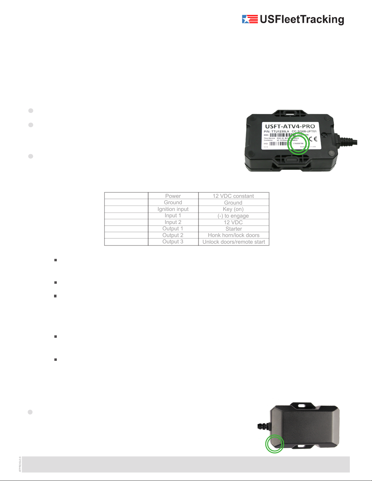
Please verify that your device is activated prior to installation. When
activating a unit, refer to the device MID# on the underside of the
tracking device. (Reference Image A.)
The AT-V4 Pro requires a standard 3-wire installation to operate effectively.
Please familiarize yourself with the following wire colors and functions.
NOTE: Do not cut the wiring harness to shorten the length of the cable as
this will void the product warranty.
The red wire (power) should be directly wired to a constant 6V - 32V power source found at the key
source or fuse panel.
The black wire (ground) should be securely fastened to a grounded screw or to chassis ground.
The white wire (ignition) is the ignition event wire that is installed directly to the ignition wire.
Ensure that power to the ignition wire is available ONLY when the vehicle ignition is turned on. All
makes and models of vehicles are different - we recommend you make sure that you know your
particularvehicle’sConstantandIgnitionwiresandtheirspeciccolor(s)priortoinstallation.
The blue and orange wires are input wires. These can be used to monitor PTO activity (Power Take Off)
suchasemergencylights,doorsopening,at-bedoperation,buckets,etc.
The green, brown, and yellow wires are output wires. These can be used for enabling and disabling the
starter, locking and unlocking doors, honking the horn, etc.
Step 1: Wiring and Installation
Thank you for purchasing your new GPS vehicle tracking system!
Installation of your new GPS tracking device couldn’t be easier.
Just follow these simple steps.
Step 2: Status LED Lights
After installing the unit, and prior to securing it under the dash area, make
sure the unit has a solid green light and a blinking orange light that goes solid
for 1 second, then repeats the pattern. See the table for troubleshooting when
one or both does not occur. (Reference Image B and Table on Page 2.)
Image B
Red wire
Black wire
White wire
Blue wire
Orange wire
Power
Ground
Ignition input
Input 1
Input 2
12 VDC constant
Ground
Key (on)
(-) to engage
12 VDC
Green wire
Brown wire
Yellow wire
Starter
Honk horn/lock doors
Unlock doors/remote start
* Must be connected for device to work properly.
*
*
*
Image A
Install
AT-V4 Pro
The AT-V4 Pro Install Guide
We recommend installation of your device by a professional installer.
Please verify that your device is activated prior to installation. When
activating a unit, refer to the device MID# on the underside of the
tracking device. (Reference Image A.)
The AT-V4 Pro requires a standard 3-wire installation to operate effectively.
Please familiarize yourself with the following wire colors and functions.
NOTE: Do not cut the wiring harness to shorten the length of the cable as
this will void the product warranty.
The red wire (power) should be directly wired to a constant 6V - 32V power source found at the key
source or fuse panel.
The black wire (ground) should be securely fastened to a grounded screw or to chassis ground.
The white wire (ignition) is the ignition event wire that is installed directly to the ignition wire.
Ensure that power to the ignition wire is available ONLY when the vehicle ignition is turned on. All
makes and models of vehicles are different - we recommend you make sure that you know your
particularvehicle’sConstantandIgnitionwiresandtheirspeciccolor(s)priortoinstallation.
The blue and orange wires are input wires. These can be used to monitor PTO activity (Power Take Off)
suchasemergencylights,doorsopening,at-bedoperation,buckets,etc.
The green, brown, and yellow wires are output wires. These can be used for enabling and disabling the
starter, locking and unlocking doors, honking the horn, etc.
Step 1: Wiring and Installation
Thank you for purchasing your new GPS vehicle tracking system!
Installation of your new GPS tracking device couldn’t be easier.
Just follow these simple steps.
Step 2: Status LED Lights
After installing the unit, and prior to securing it under the dash area, make
sure the unit has a solid green light and a blinking orange light that goes solid
for 1 second, then repeats the pattern. See the table for troubleshooting when
one or both does not occur. (Reference Image B and Table on Page 2.)
Image B
Red wire
Black wire
White wire
Blue wire
Orange wire
Power
Ground
Ignition input
Input 1
Input 2
12 VDC constant
Ground
Key (on)
(-) to engage
12 VDC
Green wire
Brown wire
Yellow wire
Starter
Honk horn/lock doors
Unlock doors/remote start
* Must be connected for device to work properly.
*
*
*
Image A
Install
AT-V4 Pro
The USFT AT-V4 Pro Install Guide
Step 1: Wiring and Installation
Thank you for purchasing your new GPS vehicle tracking system!
Installation of your new GPS tracking device couldn’t be easier.
Just follow these simple steps.
Image A
Step 2: Status LED Lights
After installing the unit, and prior to securing it under the dash area, make
sure the unit has a solid green light and a blinking orange light that goes solid
for 1 second, then repeats the pattern. See the table for troubleshooting when
one or both does not occur. (Reference Image B and Table on Page 2.)
Image B
405.726.9900 | 2912 NW 156th Street | Edmond, Oklahoma 73013 | www.usfleettracking.com
Red wire
Black wire
White wire
Blue wire
Orange wire
Power
Ground
Ignition input
Input 1
Input 2
12 VDC constant
Ground
Key (on)
(-) to engage
12 VDC
Green wire
Brown wire
Yellow wire
Starter
Honk horn/lock doors
Unlock doors/remote start
* Must be connected for device to work properly.
*
*
*
We recommend installation of your device by a professional installer.
Please verify that your device is activated prior to installation. When
activating a unit, refer to the device MID# on the underside of the
tracking device. (Reference Image A.)
The AT-V4 Pro requires a standard 3-wire installation to operate effectively.
Please familiarize yourself with the following wire colors and functions.
NOTE: Do not cut the wiring harness to shorten the length of the cable as
this will void the product warranty.
The red wire (power) should be directly wired to a constant 6V - 32V power source found at the key
source or fuse panel.
The black wire (ground) should be securely fastened to a grounded screw or to chassis ground.
The white wire (ignition) is the ignition event wire that is installed directly to the ignition wire.
Ensure that power to the ignition wire is available ONLY when the vehicle ignition is turned on. All
makes and models of vehicles are different - we recommend you make sure that you know your
particularvehicle’sConstantandIgnitionwiresandtheirspeciccolor(s)priortoinstallation.
The blue and orange wires are input wires. These can be used to monitor PTO activity (Power Take Off)
suchasemergencylights,doorsopening,at-bedoperation,buckets,etc.
The green, brown, and yellow wires are output wires. These can be used for enabling and disabling the
starter, locking and unlocking doors, honking the horn, etc.


