USA Dance Floor ARCH-RGB Manual instruction

The
“ARCH-RGB”
Portable Lighted Dance Floor System
SETUP
and
OPERATION
INSTRUCTIONS
A product of
USA Dance Floor, LLC
Made in the U.S.A.

Getting Started
Get familiar with all the parts. First there is the 4 foot by 4 foot dance floor section or Floor Panel. Each
Floor Panel has two sides or edges that are trimmed and two sides that are open or have no trim. These
open edges are completed when connected to a jointing panel. However these open edges will need
trim pieces attached all along two edges of the finished setup. See the section The Tri Piees.
Figure 1-1:
The ARCH Portable Lighted Dance Floor System
Copyright USA Dance Floor, LLC
Sockets
Trimmed Edge
Screw Holes
Dance Surface
Plugs
Trimmed Edge
Open Edges
(No trim)

Proper Floor Panel Orientation
There is only one edge of the floor panel that should be considered as the bottom when a floor panel is
transported or stored up-right on its edge. Figure 1-2 shows the proper orientation.
Figure 1-2:
Only rest the floor on this side when loading or storing upright on its edge
Note:
Always tuck the short extension Plugsinside of the floor panel for transporting.
The ARCH Portable Lighted Dance Floor System
Copyright USA Dance Floor, LLC
Plugs

The Trim Pieces
Trim pieces come in two types and sizes. One type is Non-Powered Trimpieces and the other is
Powered Trimpieces.
POWERED TRIM PIECES
Powered trim pieces are the wired trim. These are used to finish one of the two open edges of the floor
while hiding the wires that supply power. The floor panels are plugged into the sockets of the powered
trim and then the pieces are secured to the floors by way of stainless steel screws.
Poered etesios are used etee the ai poer ale’s orer tri ad aother poered
extension or powered end piece.
Powered end pieces are always used at the end of a length. (See Figure 1-5)
Figure 1-3:
8 foot powered extension
(95 13/16 .)
8 foot powered end piece
(89 7/8 .)
4 foot powered end piece
(41 7/8 .)
NON-POWERED TRIM PIECES
Non-powered trim pieces have no wiring. These are used to finish the second open floor edge. Trim
extensions are used for extending to a jointing four or eight foot length. End pieces are used to finish the
end of a length. These trim pieces do not connect to each other. Rather they connect directly to the
floor sections by way of stainless steel screws.
Figure 1-4:
8 foot trim extension
(95 13/16 .)
8 foot trim end piece
(89 7/8 .)
4 foot trim end piece
(41 7/8x .)
NOTE: The optional slopped edging is secured to the trim pieces with special screws-in holes.
The ARCH Portable Lighted Dance Floor System
Copyright USA Dance Floor, LLC

Proper Trim Placement
Figure 1-5 shows how to use 8 foot trim pieces on a 24x24 floor. The eight foot extensions are used first
in line from the main power connector. All extensions are 8 feet in length. The end trim pieces are used
last or at the ends. End trim pieces are 8 feet or 4 feet in length.
Figure 1-5
Powered
End Trim Piece
(This is the shorter 8 foot)
Powered
Extension Trim Piece
Powered
Extension Trim Piece
Non-Powered Non-Powered Non-Powered
End Trim Piece Extension Trim Piece Extension Trim Piece Main
(This is the shorter 8 foot) Power
Cable
The ARCH Portable Lighted Dance Floor System
Copyright USA Dance Floor, LLC

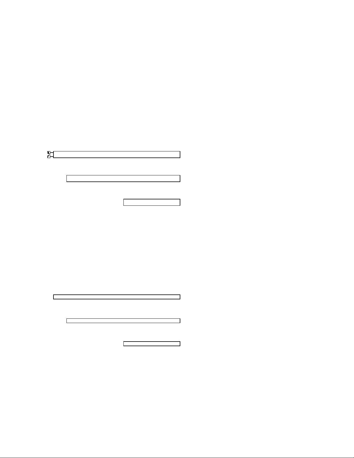
Screwing the Floor Panels Together
One inch stainless steel screws are used to hold the floor paels to eah other ad keep the pael’s leel
with each other. Screws should never ever be tight. At first the sres should ol e started ad kept
loose during assembly as shown in figure 1-7. This will keep the panels free to move as the panels
square up to each other. Only after all screws have been started in all the panels and edging the screws
may be secured. If you are installing beveled edging start all those screws as well before securing any
other screws.
NOTE: A power drill may be used to secure screws only if it has a ratchet drive set at low torque.
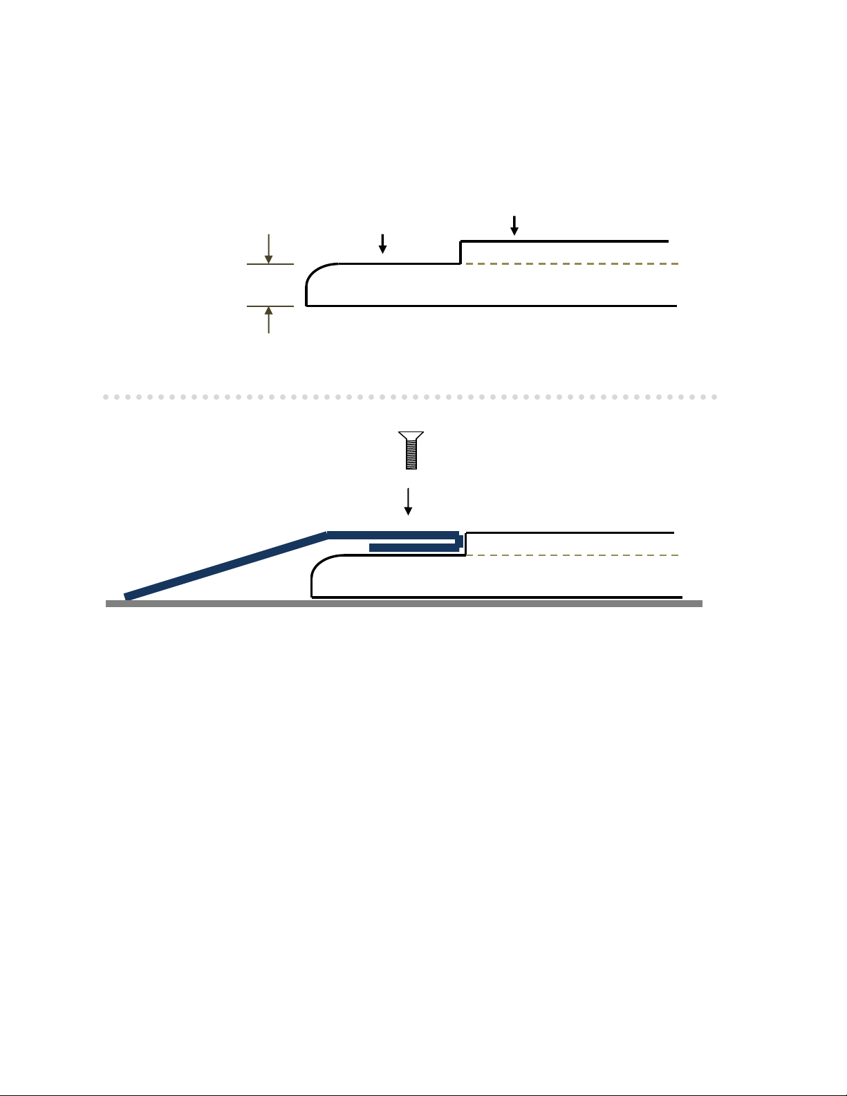
Securing a screw does not mean to tighten it. Securing a screw means that the top of the
sre’s head is leel ith or elo the dae floor surfae as sho i figure -8.
NOTE: If a bolt binds, cross threads or won’t go in straight… skip it. It is ok to have a missing bolt
here and there then to cross thread or bind a screw.
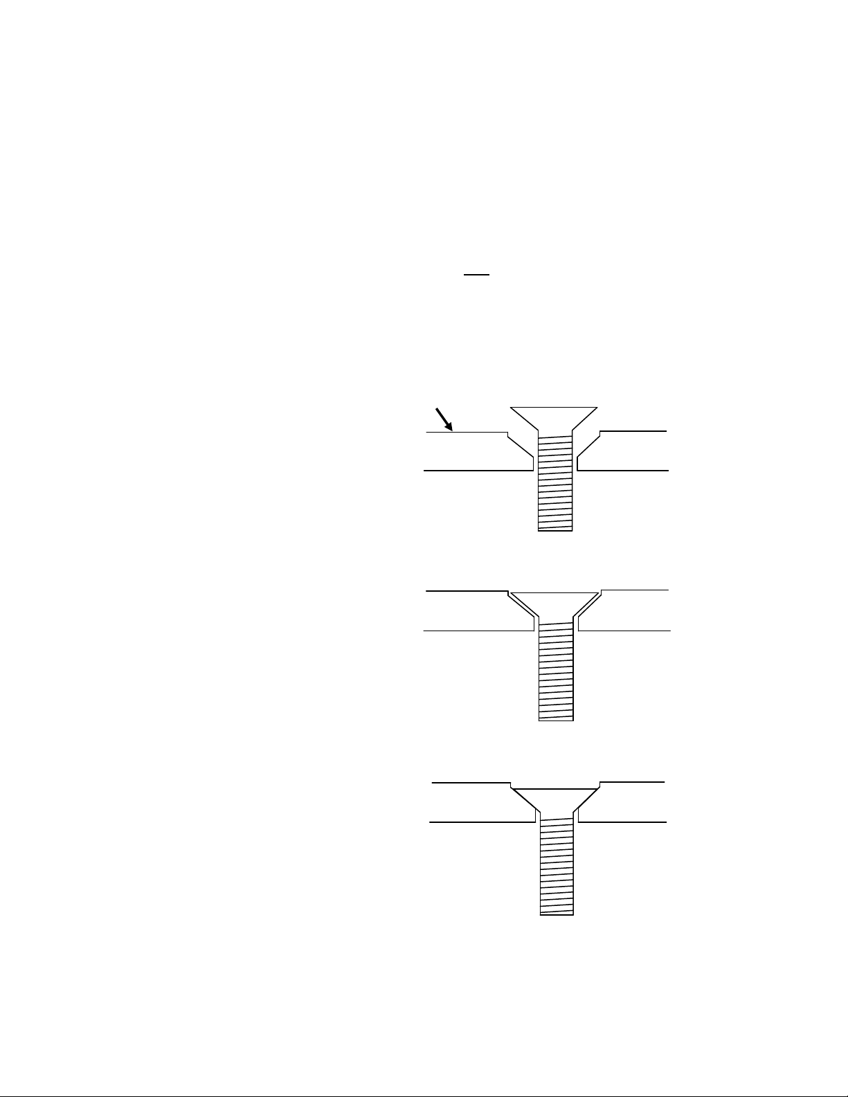
Figure 1-7 Dance Floor surface
The cutaway drawing on the right shows
the screw in the started position.
Figure 1-8
This drawing shows the screw in the
securedposition. Notice there is room
to allow for flexing and movement.
Figure 1-9
This drawing shows the screw too tight.
This can cause the floor to crack.
The ARCH Portable Lighted Dance Floor System
Copyright USA Dance Floor, LLC

The Dance Floor Panel’s Outside Edging
The edge of a dance floor panel is only ¾ of an inch high and is rounded. The edging of the floor can be
finished without beveled edging as shown in figure 1-10 or with beveled edging as shown in figure 1-11.
Figure 1-10 Dance Floor Surface
Outside Edge
¾ inch
Figure 1-11
Optional
Aluminum Beveled Edging
NOTE: All new floors come with brand new never been used plugs and sockets. This means they may
tend to be stiff and fit tight at first. To fix this it is recommended to apply a little marine grease on all the
connections.
The ARCH Portable Lighted Dance Floor System
Copyright USA Dance Floor, LLC

Order of Assembly
Figure 1-12:
This figure shows all the main components for assembling a 12x8 floor
and It shows the proper sequence the floor panels are to be assembled.
Always finish the first row of panels before starting the second.
Finish the second row before starting the third and so on. Main
Power Cable
NOTE: It is always a good idea to power up and test the floors
after assembling a row to confirm all connections.
’ tri end 8’ etesio tri
3 2 1
Third Floor Second Floor First Floor
Panel Panel Panel
8’ Tri
end
6 5 4
Sixth Floor Fifth Floor Fourth Floor
Panel Panel Panel
NOTE: All new floors come with brand new never been used plugs and sockets. This means they may
tend to be stiff and fit tight at first. To fix this it is recommended to apply a little marine grease on all the
connections.
The ARCH Portable Lighted Dance Floor System
Copyright USA Dance Floor, LLC

The Master or Main Power Cable is the cord that runs from the floor system to the power supply box.
One end is a multi pin connector that plugs into the power supply. Orientation is critical when plugging
this plug in. The other is an L shaped corner floor trim piece that connects in the corner of the floor
where the Powered and Non-Powered trim pieces come together. The plugs coming from this piece
connects power to the Powered Trim.
Figure 1-13
Fig. 1-14shows the Main Supply cable and Powered Trim Piece upside-down.
Figure 1-14
The ARCH Portable Lighted Dance Floor System
Copyright USA Dance Floor, LLC

SETUP INSTRUCTIONS:
To setup a floor first determine the position of the floor and the corner where you want the main power
cable. Figure 1-15 shows the powered corner floor trim piece at the corner of the floor panel with
adjoining edge trim pieces.
Figure 1-15
The next step should be to connect the Main Power Cable and the Powered Trim piece together. To do
this flip the L shaped corner main connector and the powered trim upside-down as shown in
Figure 1-16.
Figure 1-16
Remove the four screws holding the cover to the Powered Extension Trim Piece. This will expose the
plug and socket for connecting to the main power connector piece. Make the connections as shown in
Figure 1-16 and replace the cover. Be sure not to pinch wires. Then flip the pieces right side up as in
Figure 1-15. Start laying Floor Panels down starting in the corner as shown in Figure 1-12. The next step
will be connecting the Floor Panel plugs to the trim sockets and bolting the Floor Panels to the Trim
Pieces.
The ARCH Portable Lighted Dance Floor System
Copyright USA Dance Floor, LLC

DO NOT TIGHTEN BOLTS YET!
The bolts should never be secured until ALL olts hae ee Started. Startig a olt eas the olt is
hand screwed partway into the screw hole. Start ith the L shaped oetor as sho i Figure -17.
Figure 1-17
There should never be any binding or cross threading. Use a screwdriver to pry the holes inline and start
screwing the bolt in. (See Fig. 1-17) Only start it and leave it loose until all bolts to the entire floor has
been started. (See Fig. 1-18) Keeping the blots loose will allow you to square up panels as you assemble.
Figure 1-18
The ARCH Portable Lighted Dance Floor System
Copyright USA Dance Floor, LLC

Connect the two plugs from the Floor Panel to the corresponding sockets on the Powered Trim as shown
in Figure 1-19 and 1-20. Be sure the connections are solid.
Figure 1-19 Figure 1-20
Then slide the Powered trim and the Main Supply Cable’s tri piee in place under the Floor Panel. Line
up the screw holes in the trim with the holes in the Floor Panel and start the bolts. Six one inch stainless
steel bolts will secure the Floor Panel to the trim. After the first panel is installed it should look like
Figure 1-21.
Figure 1-21
NOTE: If the bolt binds, cross threads or won’t start skip it. It is ok to have a missing bolt here and there
then to cross thread or bind it. If a screw gets cross threaded or stripped and stuck there is only one way
to fix It without cracking a floor panel. See the instructions on Ho to Remoe a Stuck Scre.
Continue placing panels as shown in Figure 1-12. Start the next row by connecting plugs to the first
panel’s sokets. Continue placing panels to the left and so on. Non-powered trim pieces can be
attached at any time during the assembly. Secure all bolts only when all done.
The ARCH Portable Lighted Dance Floor System
Copyright USA Dance Floor, LLC

WARNING
NEVER OVER TIGHTEN BOLTS!
When securing bolts they should only be snug. This allows the floor to flex. Tightening too tight can
cause the floor to crack or strip a screw hole.
WEAR GLOVES!
There are sharp edges, always wear gloves.Anyone handling the panels at anytime should always be
wearing gloves. To help prevent a static charge it is recommended that the gloves are made of cotton. It
is also recommended that anyone handling the acrylic floor panels should not be wearing any wool or
silk clothing. These materials tend to build a static charge when rubbed against the acrylic surface.
The ARCH Portable Lighted Dance Floor System
Copyright USA Dance Floor, LLC

Part 2 - OPERATION
INSTRUCTIONS
Figure 2-1:
Connections:
Your power supply and controller is shipped all ready for audio or sound control. Step one is to plug the
floor’s ai poer ale ito the back of the unit. Second is to plug 120VAC power cord into AC inlet
and plug into a wall receptacle.
Operation:
Once the unit is plugged into power it will power up. There is no power on/off switch. Both Black-Out
buttons will be flashing. This means the floor will be black or off.
NOTE: It is normal to see the floor flash white when first powered on.
To operate i soud atiatio ode press the to Soud Atie uttos. This ill light their LED’s.
The set the B faders oth to %. By pressing each Black-Out button once the floor will light up to
the sounds in the room. There are tiny microphones built-in and the sensitivity can be adjusted with the
B fader otrols.
To operate with patterns and colors please follow the directions in the manual for the RGB-3C.
The ARCH Portable Lighted Dance Floor System
Copyright USA Dance Floor, LLC

Power Specifications
POWER INPUT:
Voltage range: 90 –264VAC
Frequency range: 47 -63Hz
POWER OUTPUT (to the floor panels):
Voltage output: 12VDC
Current range: 0 –62.5amps.
Rated power: 750 watts
Line & Load regulation: 0.5%
RGB FLOOR PANEL LOAD: (at full on)
One panel draws: 14.4 Watts @ 12VDC
Maximum load: 54 floor panels
Sq. footage: 864
An optional DMX power supply is also available. The DMX power supply turns your dance floor
system into a ten channel DMX light fixture that may be controlled by most any DMX lighting
controller. Contact your USA Dance Floor representative for more information.

CLEANING
All that is needed to clean the dance surface is water and a clean rag. Never use anything abrasive.
Whateer does ot oe off ith ater a e reoed ith Goof Off reoer ad a lea rag.
We have tested many cleaners and recommend Goof Off brand professional strength remover (in the
yellow can). It can be used to clean any parts of the floor panels and trim. Simply wet a clean rag with
Goof Off and wipe.
WARNING
There are sharp edges, always wear gloves.
There are sharp edges. Anyone handling the panels at anytime should always be wearing gloves. To help
prevent a static charge it is recommended that the gloves are made of cotton. It is also recommended
that anyone handling the acrylic floor panels should not be wearing any wool or silk clothing. These
materials tend to build a static charge when rubbed against the acrylic surface.
The ARCH Portable Lighted Dance Floor System
Copyright USA Dance Floor, LLC
Table of contents