- 11 -
CM-680 INSTRUCTION MANUAL Ultra Stereo Labs, Inc.
- 4 -
CM-680 INSTRUCTION MANUAL Ultra Stereo Labs, Inc.
You will need to supply the following materials:
S ielded audio cable for connecting t e CM-680 to t e
cinema processor and power amplifier outputs.
Four 10-32 x 1/2" screws to mount t e CM-680 in t e audio
equipment rack.
FEATURES
The CM- 80 monitor has the following standard features:
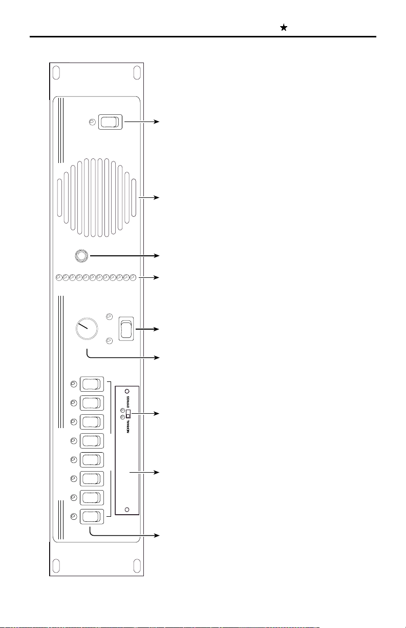
Eig t-C annel Monitoring - allows you to monitor eit er t e
processor or power amplifier outputs to left, center, rig t,
surround left, surround rig t, back surround left, back surround
rig t and subwoofer c annels, in any combination via t e switc
on t e front panel (see illustration on pg. 5 - switc 5)
Input levels from processor and power amplifier can be
adjusted independently - no uge level jumps w en switc ing
between processor and power amplifiers.
Bargrap display may be calibrated to t e reference level
for your t eatre t e projectionist can see auditorium levels
instantly.
Designed to work wit bi-amplified sound systems to
monitor t e ig and low frequency outputs from t e left,
center and rig t c annels.
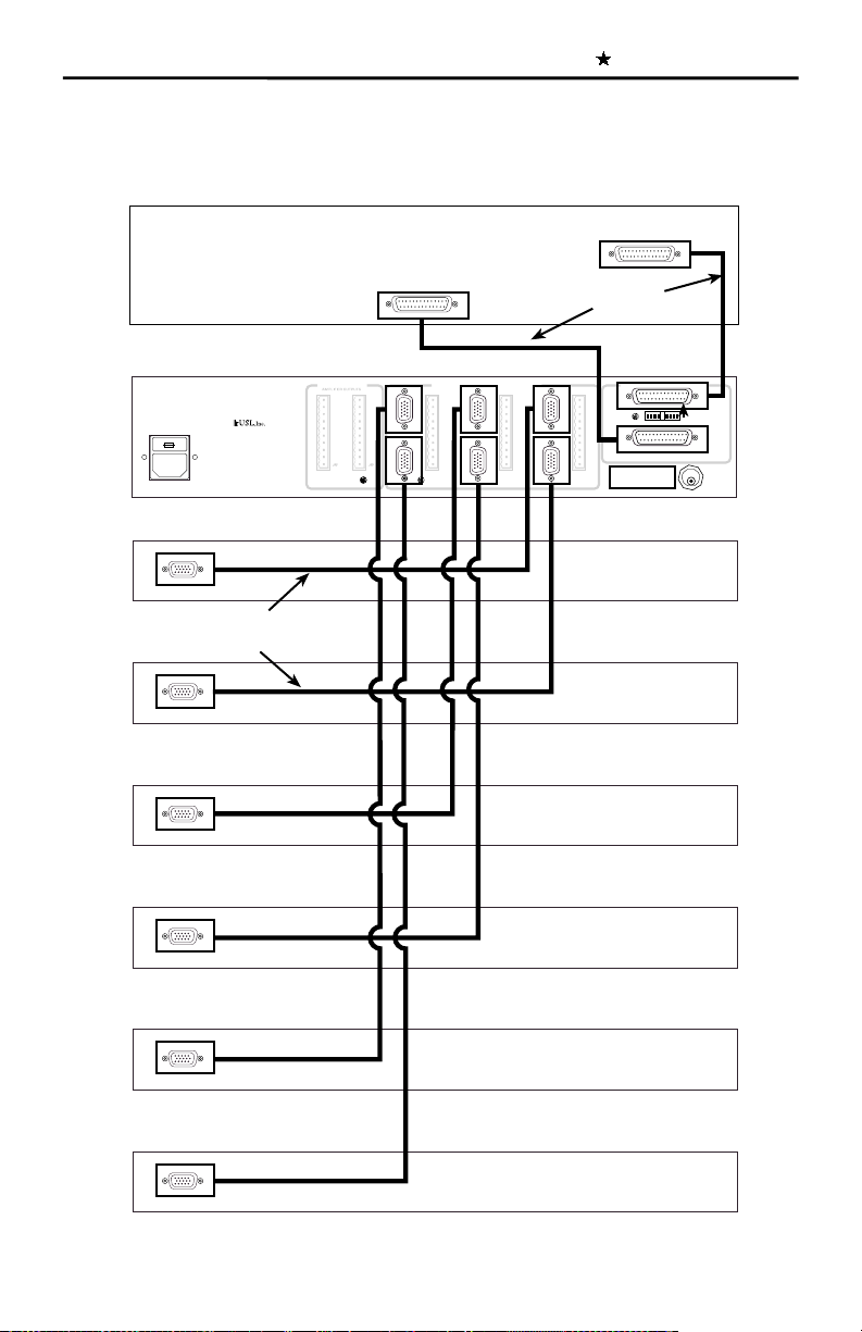
Crossover Setup
Analog Crossover Card XTA- 80: W en using t e USL, Inc. Crossover
card, t e following parameters must be set: time delay, crossover frequency,
orn EQ, Screen EQ and output levels. See figure #6.
Make sure t e NORMAL/BYPASS switc is set in t e NORMAL position.
Determine t e model number of t e speaker system being used. (Figure #7
as a listing of several popular cinema loudspeakers.)
If your loudspeaker requires a 1.8 ms delay, turn ON all DIP switc es on
t e first row marked 1.8 ms. Refer to figure #7. Likewise a loudspeaker
requiring 1.4 ms delay s ould require all t e DIP switc es in t e second row
to be turned ON.
For loudspeakers requiring only 0.7 ms delay, leave all t e time delay DIP
switc es OFF. Never turn on both rows of time Delay switches!
Next, set t e crossover frequency. For 800Hz, turn all t e crossover frequency
DIP switc es in t e first row ON. For 500Hz, turn all t e DIP switc es in
t e second row ON. For 330Hz, turn all t e DIP switc es in t e t ird row
ON. For 297 Hz, leave all t e crossover frequency DIP switc es OFF.
Never turn on more than one row of DIP switches.
Now, set t e orn EQ and screen EQ DIP switc es. Generally, all six DIP
switc es s ould be ON. In some cinemas, t e left and rig t speakers are
mounted outside t e screen area. In t is case, turn t e left and rig t screen
EQ switc es to OFF. Some ig frequency orns are very flat to 20kHz.
In t is case, you may want to turn t e orn EQ switc es to OFF. T e orn
and screen EQ eac provide about 8dB of boost at 20kHz. T e combination
of orn and screen EQ results in about 16 dB boost at 20kHz.
Finally, set t e output levels. Using a Real Time Analyzer and feeding a pink
noise signal from t e cinema processor, set t e appropriate ten turn pots
for a flat response around t e crossover frequency and a total SPL level of
85 on eac of t e front t ree c annels. T ere s ould be enoug range in
t e output pots to allow setting t e amplifier gains at maximum or at t e 12
Oclock position.
T e bypass crossover is fixed at about 500 Hz wit no time delay. Using a
Real Time Analyzer and feeding pink noise from t e center c annel of t e
cinema processor, set t e bypass levels for flat response around 500 Hz
and an SPL level of 85. T e NORMAL/BYPASS switc will need to be set
in BYPASS.