Vauconsant REVERSO User manual

1
Instructions of use and maintenance page 2
Electric and refrigerating diagrams page 3
Manual of the thermostat page 4 - 6
Spare parts page 7
Rue Charles Hermite Z.I. des Sables BP 59
54110 Dombasle sur Meurthe France
tel : (+33) 03 83 45 82 82 - fax : (+33) 03 83 45 82 93
REVERSO

2
INSTRUCTION OF USE AND MAINTENANCE
GENERAL POINT
Refrigerating components
Well : Refrigeration by a ventilated evaporator located in the
well.
Well bain-marie pulsated air
One or two stainless steel resistance shield with blades,
located in a box.
Option crawl heating halogen
Heating and lighting by halogen lights.
Lighting
Lighting by fluorescent tube.
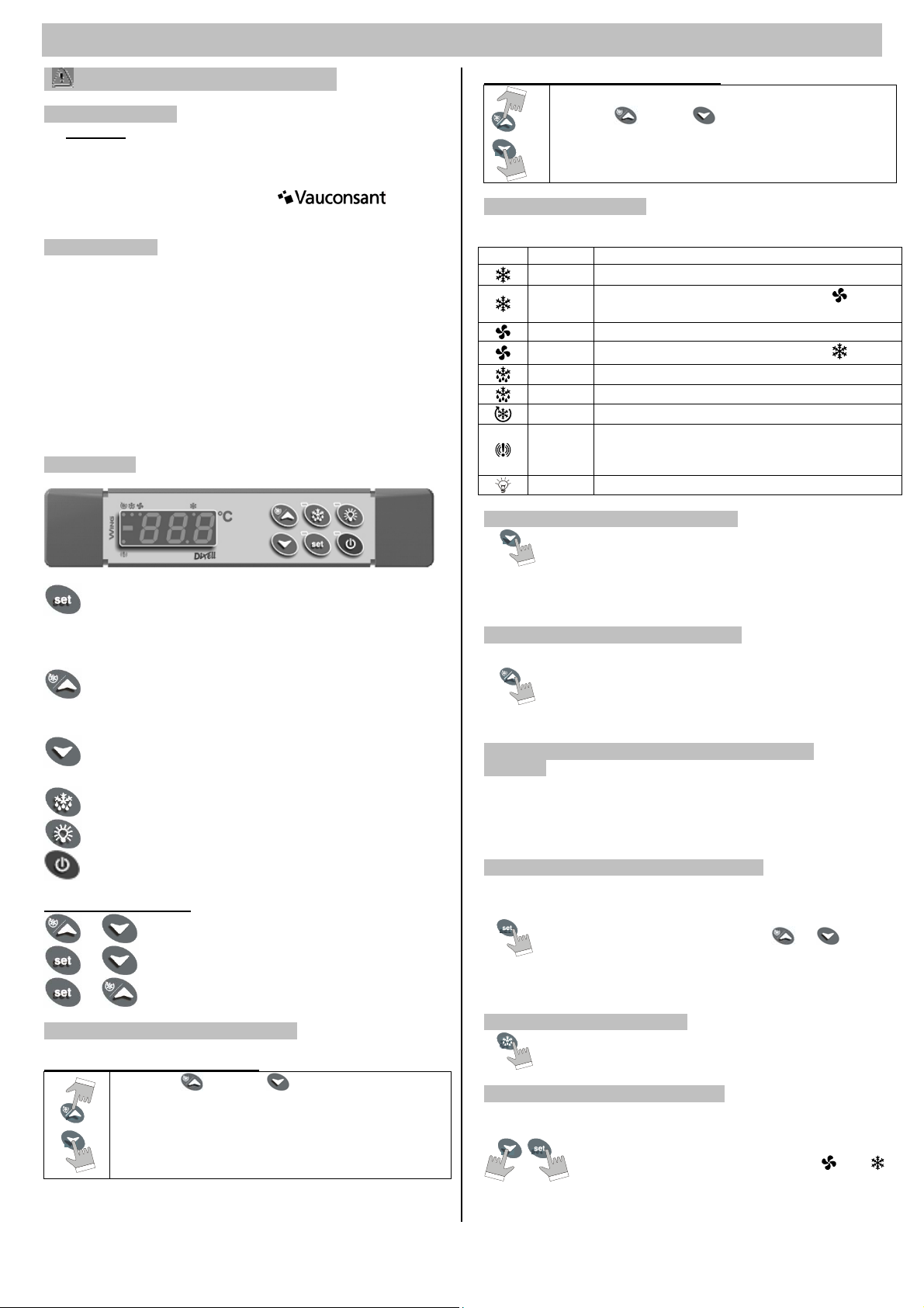
Controls
A 4 positions switch to select the function mode desired.
Froid : High precision control by thermostat Dixell XR40 with
digital display ( to refer to the note of the thermostat provided
hereafter ).
Chaud : High precision control by thermostat Dixell XT110C
with digital display ( to refer to the note of the thermostat
provided hereafter ).
Halogen lamp : Variator
Fluorescent tub : a switch on/off
Controls located on the control’s panel
Protection
By main power fuse holder.
INSTALLATION
To set up the drop-in unit
Settle the black neoprene watertight joint on the perimeter
of the drop-in unit before the definitive installation.
To embed the well ventilated in cutting envisaged.
Electric connection
Before plugging in the unit, control imperatively the
voltage rating : it should be the same voltage as
indicated on the unit.
The electric power line providing the refrigerated unit with
electricity should be protected by a differential circuit breaker
located on the main electric distribution panel.
To connect the incoming line to the fuse holder located in the
electric box.
To connect the plug of the self evaporating tray.
Compressor connection
To connect the refrigerating circuit, in accordance with the
refrigerating diagram, provided hereafter.
To connect the two strikers by tighten with adequate spanner,
the tightening became hard during the impact of the strikers, the
tightening must be continued to have a good airtightness. A
wrong tighten of the strikers can generate a flight of the
refrigerating gas and failure of the equipment.
It is recommended to check the airtightness of the
strikers with detector of flight, after the tighten of the
strikers.
To set up the self evaporating tray
The self evaporating tray must be placed under the unit, at
the place designed, by means of the clips initially installed.
The installation twist of the self evaporating tray must be
connected to the plug of the electric box, according the
standard of unit, the twist of the self evaporating tray can be
situed in the face or in the back of the unit.
Astainless steel sheet deflector located in the self
evaporating tray, allow to direct the water vapour. The sheet
must be located in the middle of the self evaporating tray ( the
same distance in each side).
The deflector must be located to have the good direction of
the inclination, like described in the following diagram.
UTILISATION
To put into service
Powering up the unit two hours before usage.
Switch on the function mode desired : Chilled ventilated air
function, Hot ventilated air function, Dry Bain Marie
function.
The corresponding thermostat turn on.
The thermostat is adjusted in the factory after testing.
When the desired temperature is obtained, the power unit
automatically turns off.
Positionner le commutateur sur la position 0 pour arrêter le
fonctionnement du reverso.
Dry Bain-marie function
150 mm deep gastronorm GN 1/1 trays should be
used.
With the parameters programs in factory, the food’s
temperature is maintened above +65°C which is the minimum
temperature defined by Health Departments.
To be able to hold this temperature, it is essential to bring
food to a temperature ranging between +70°C and +80°C.
Lightning
Press the switch on/off to turn on or turn off the lighting
Turn to the right the variator to turn on the halogen lamps.
Adjusting the thermostat
Refer to the manual for details.
Automatic defrosting
This function is programmed in the thermostat/
Adjusted in the factory: the defrosting engages every hour
throughout one ten maximum minute.
To modify the adjustment, refer the manual of the
thermostat.
Cleaning
To be performed when the unit is shut down (the unit is
turned off).
Once a day, wash the top, the refrigerated well and the
external sides of the unit.
Use a sponge moistened with a soapy water or special
cleaning products to clean the stainless steel. Rinse off with
water. Dry preferably with lint-free cotton cloths.
Do not use floor cleaning products or acids, even diluted,
chlorinated or scouring products, which may cause corrosion to
stainless steel.
Do not use any abrasive products (steel wool, etc…).
Do not clean the refrigerated unit by spraying with water,
using a soap gun, or under high pressure jets.
MAINTENANCE
The installer should check all the electric connections during
the initial start up of the unit (and then once a year).
Clean the condenser every six months.
Grease the condenser blower shaft once a year.
deflecto
r

3
ELECTRIC DIAGRAM
REFRIGERATING DIAGRAM
CAPTION DIAGRAMS
B Ballast Rb Self-evaporating tray heating element
C Compressor Rd Defrost heating element
Ca Capillary Sf Starter
Cd Condensor Sn Level probe
D Relief valve St
A
tmosphere temperature probe
Dh Drier Tb Safety thermostat for self evaporating tray
E Evaporator Tf Fluorescent tub
I 4 positions switch Tr Thermostat XR40
Kb Self evaporating tray relay Ts Safety Thermostat
Kd Defrost relay V Well ventilator
Lh Halogen lamp Va
V
ariator
Q Fuse holder Vc Condensor fan
R Heating element

4
MANUAL OF THERMOSTAT XW40L
Please read this manual before using
1.AVERTISSEMENT
•Warning: disconnect all electrical connections before
any kind of maintenance.
•The instrument must not be opened.
•In case of failure or faulty operation send the instrument
back to the distributor or to with a
detailed description of the fault.
2.DESCRIPTION
Model XW40L is microprocessor based controllers suitable
for applications on medium or low temperature refrigerating
units. They are provided with 3 relay outputs to control
compressor, defrost - which can be either electrical or hot gas
- and the lights. They are also provided with 1 NTC or PTC
probe inputs, for temperature control.
The regulation is performed according to the temperature
measured by the thermostat probe with a positive differential
from the set point: if the temperature increases and reaches set
point plus differential the compressor is started and then turned
off when the temperature reaches the set point value again.
3.KEYBOARD
To display and modify target set point; in
programming mode it selects a parameter or confirm
an operation.
By holding it pressed for 3s when max or min
temperature is displayed it will be erased.
To see the max. stored temperature; in programming
mode it browses the parameter codes or increases the
displayed value. By holding it pressed for 3s the fast
freezing cycle is started.
To see the min stored temperature; in programming
mode it browses the parameter codes or decreases the
displayed value.
By holding it pressed for 3s the defrost is started.
Switch ON and OFF the light of the cold-room.
Switch ON and OFF the instrument.
KEY COMBINATIONS
+ To lock and unlock the keyboard.
+ To enter the programming mode.
+ To exit the programming mode.
3.1 To lock and unlock the keyboard
HOW TO LOCK THE KEYBOARD
Keep the and the keys together for more
than 3 s. The "POF" message will be displayed and
the keyboard is locked. At this point it is only
possible the viewing of the set point or the MAX or
Min temperature stored and to switch ON and OFF
the light, the auxilary output and the instrument.
HOW TO UNLOCK THE KEYBOARD
Keep the and the keys pressed together for
more than 3 s. The "POn" message will be displayed
and the keyboard is unlocked.
3.2 Meaning of the LED
Each LED function is described in the following table :
LED MODE FONCTION
ON The compressor is running
Flashing Programmation phase ( flashing with )
Anti-short cycle delay enabled
ON The fan is running.
Flashing Programmation phase ( flashing with )
ON The defrost is enabled.
Flashing Drip time in progress
ON The fast freezing cycle is enable
ON
Alarm signal
In “Pr2” indicates that the parameter is also
present in “Pr1
ON The light is on
3.3 How to see the min temperature
Press and release the nkey.
The “Lo” message will be displayed followed by the
minimum temperature recorded.
By pressing the nkey or waiting for 5s the normal
display will be restored.
3.4 How to see the max temperature
Press and release the okey.
The “Hi” message will be displayed followed by the
maximum temperature recorded.
By pressing the okey or waiting for 5s the normal
display will be restored.
3.5 How to reset the max and min temperature
recorded
To reset the stored temperature, when max or min temperature
is displayed, press SET key until “rST” label starts blinking.
N.B. : After the installation RESET the temperature
stored .
3.6 How to see and modify the set point
Push and immediately release the SET key: the
display will show the Set point value.
The SET LED start blinking.
To change the Set value push the or arrows
within 10s.
To memorise the new set point value push the SET
key again or wait 10s.
3.7 To start a manual defrost
Push the DEF key for more than 2 seconds and a
manual defrost will start.
3.8 To enter in parameters list Pr1
To enter the parameter list “Pr1” (user accessible parameters)
operate as follows:
Enter the Programming mode by pressing the
Set and DOWN key for few seconds ( and
start blinking).
The instrument will show the first parameter
present in “Pr1”.

5
3.9 To enter in parameters list Pr2
To reach the parameters present in "Pr2" (parameters
accessible to the technicians), please contact ,
which will deliver you the secret code making it possible to
reach these parameters.
4. ALARM SIGNALS
Message Cause Output
"P1" Thermostat probe
failure
Alarm output ON; Compressor
output according to parameters
“COn” and “COF”
"HA" Maximum
temperature alarm
Alarm output ON; Other outputs
unchanged
"LA" Minimum
temperature alarm
Alarm output ON; Other outputs
unchanged
"EE" Data or memory
failure
Alarm output ON; Other outputs
unchanged
The alarm message is displayed until the alarm condition is
recovery.
All the alarm messages are showed alternating with the room
temperature except for the “P1” which is flashing. To reset the
“EE” alarm and restart the normal functioning press any key,
the “rSt” message is displayed for about 3s.
4.1 EE alarm
The instruments are provided with an internal check for the
data integrity. Alarm “EE” flashes when a failure in the memory
data occurs. In such cases the alarm output is enabled.
4.2 Alarm recovery
Probe alarms “P1” (probe1 faulty), “P2” ; they automatically
stop 10s after the probe restarts normal operation. Check
connections before replacing the probe.
Temperature alarms “HA” and “LA” automatically stop as soon
as the thermostat temperature returns to normal values or
when the defrost starts.
5. PARAMETERS PROGRAMS IN FACTORY
Parameter Name Default
Set Set point 2
Hy Differential 1
AC Anti-short cycle delay 1
rES Resolution (integer/decimal point) de
tdF Defrost type rE
dtE Defrost termination temperature 1
IdF Interval between defrost cycles 1
MdF (Maximum) length for defrost 4
ALU MAXIMUM temperature alarm 8
ALL Minimum temperature alarm 2
ot Thermostat probe calibration 6
P2P Evaporator probe presence n
Adr Address series (unused) 1
P2r Access parameter list ( read only) 1

6
MANUAL OF THERMOSTAT XT110C
Please read this manual before using
1.AVERTISSEMENT
•Warning: disconnect all electrical connections before
any kind of maintenance.
•The instrument must not be opened.
•In case of failure or faulty operation send the instrument
back to the distributor or to with a
detailed description of the fault.
2.GENERAL DESCRIPTION
The XT110C and XT111C are single-stage ON/OFF controllers
for temperature, humidity and pressure applications with direct
or inverse action, user-selectable. The analogue input type can
be set by parameter between the following, according to the
model:
-PTC, NTC;
-PTC, NTC, Pt100, Thermocouple J, K, S;
4÷20mA, 0÷1V, 0÷10V.
3.FRONT PANEL COMMAND
SET: To display and modify target set point; in programming
mode it selects a parameter or confirm an operation.
TO SWITCH THE INSTRUMENT ON/OFF: If the function
is enabled (par. onF=yES), by pressing the SET key for
more than 4s the controller is switched OFF. To switch the
instrument on again press the SET key.
oUP: in programming mode it browses the parameter codes or
increases the displayed value. Hold it pressed for a faster
change
nDOWN: in programming mode it browses the parameter
codes or decreases the displayed value. Hold it pressed for
a faster change
KEY COMBINATIONS:
o + nTo lock & unlock the keyboard.
SET + nTo enter in programming mode.
SET + o To return to the room temperature display.
3.1 Use of LEDs
Each LED function is described in the following table :
LED MODE FUNCTION
ON Output relay enabled
LED1 Flashing - Programming Phase (flashing with LED2)
LED2 Flashing - Programming Phase (flashing with LED1)
E.S. ON Energy saving activated by digital input
ON - ALARM signal
- In “Pr2” indicates the parameter is also present
in “Pr1”
3.2 To see the set point
Push and release the SET key to see the Set point
value
To come back to the normal display push again the SET key or
wait 10s.
3.3 To change the set point
Hold pushed the SET key for 3s to change the Set
point value
The value of the set point will be displayed and the LED1 & 2
start blinking
To change the Set value push the o or narrows within 10s.
To memorise the new set point value push the SET key again
or wait 10s.
3.4 To enter the parameters list PR1
Push for 3s the SET + n keys (LED1 & 2 start
blinking).
The controller will display the first parameter present in the Pr1
menu.
3.5 How to change a parameter
- Enter the Programming mode
- Select the required parameter.
- Press the “SET” key to display its value.
- Use “UP” or “DOWN” to change its value.
- Press “SET” to store the new value and move to the following
parameter.
TO EXIT: Press SET + UP or wait 15s without pressing a key.
NOTE: the set value is stored even when the procedure is
exited by waiting the time-out to expire.
3.6 How to lock the keyboard
Keep pressed together for more than 3s the the o and nkeys,
till the “POF” message will be displayed.
3.7 To unlock the keyboard
Keep pressed together for more than 3s the the o and nkeys,
till the “Pon” message will be displayed.
4.ALARM SIGNALS
Message Cause Outputs
“PFo”
Probe broken or
absence
Alarm output ON; Output
according to parameter
“So1”
“PFc”
Probe short circuited Alarm output ON; Output
according to parameter
“So1”
“HA”
Maximum alarm Alarm output ON; Other
outputs unchanged.
“LA”
Minimum alarm Alarm output ON; Other
outputs unchanged.
“EAL” External alarm Output unchanged.
“bAL” Serious external alarm Output OFF.
5. PARAMETERS PROGRAMS IN FACTORY
Parameter 40°C 80°C
Set 40 80
Hy1 -1 -1
LS1 20 20
US1 50 90
S1C In In
Ac 0 0
OPb 25 25

7
SPARE PARTS
Length of the unit
Code Item 870 1350 1550 1900
02.4250 Jack with gas Adlin X X X X
06.1188 Safety Thermostat X X X X
06.3410 Tangential Ventilator Ebmpapst réf. 4656 ZWU X X X X
06.4806 Starter for fluorescent tub X X X X
12.0268 Thermostat Dixell XR40C X X X X
06.1234 Thermostat Dixell XT110C X X X X
06.1072 4 positions switch X X X X
06.0706 Resistance with blades length 415 mm power 750 W X X
06.0702 Resistance with blades length 300 mm power 500 W X
06.0710 Resistance with blades length 625 mm power 1250 W X
12.2518 Evaporator length 580 X
12.2520 Evaporator length 900 X
12.2522 Evaporator length 1230 X
12.2524 Evaporator length 1550 X
Option crawl heating halogen
06.0622 Halogen lamp power 200W X X X X
06.0620 Aluminium reflector X X X X
06.0625 Protective glass + fixing X X X X
06.1520 Variator X X X X
Lighting
06.1005 Orange indicator switch X X X X
06.4778 Fluorescent tub 436 mm 12 W X
06.4782 Fluorescent tub 893 mm 30 W X
06.4784 Fluorescent tub 966 mm 36 W X
06.4786 Fluorescent tub 1196 mm 36 W X
06.4810 Ballast 15 W X
06.4811 Ballast 30 W X
06.4812 Ballast 36 W X X
SAV
Francis LECOMTE
Fax : 03 83 45 82 75
Table of contents
Popular Merchandiser manuals by other brands

frost-trol
frost-trol EYRE PM0000143343ND20 Installation and maintenance manual

Turboair
Turboair TOM-36DX Service manual

Crane
Crane BevMAX Refresh 6 Media Operation guide

Hussmann
Hussmann M5NX-E Technical data sheet

Hussmann
Hussmann IMPACT Excel D5XLRE Technical data sheet

EPTA
EPTA iarp Cool Emotions GLEE GLASS 41 User instructions

Prince Castle
Prince Castle 515-A Series TRANSLITE INSTALLATION INSTRUCTIONS

Buffalo
Buffalo CK915 instruction manual

EPTA
EPTA Costan VALZER NEXT COMPACT User instructions

Hussmann
Hussmann Impact Excel M4X-EP Technical data sheet

Howard McCray
Howard McCray R-CFS40E-4C Specifications

Hussmann
Hussmann USL-2 Installation and service instructions