4
MANUAL OF THERMOSTAT XW60L
Please read this ma ual before usi g
1.AVERTISSEMENT
•War i g: disco ect all electrical co ectio s
before a y ki d of mai te a ce.
•The i strume t must ot be ope ed.
•In case of failure or faulty operation send the instrument
back to the distributor or to with a
detailed description of the fault.
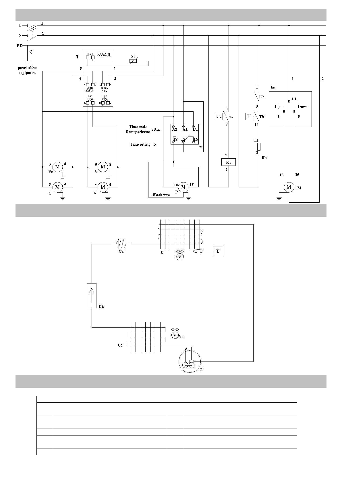
2.DESCRIPTION
Model XW60L is microprocessor based controllers suitable
for applications on medium or low temperature refrigerating
units. They are provided with 4 relay outputs to control
compressor, defrost, fans for the evaporator and the lights.
They are also provided with 2 NTC probe inputs, for
temperature control, the second for end defrost temperature
control.
The regulation is performed according to the temperature
measured by the thermostat probe with a positive differential
from the set point: if the temperature increases and reaches
set point plus differential the compressor is started and then
turned off when the temperature reaches the set point value
again.
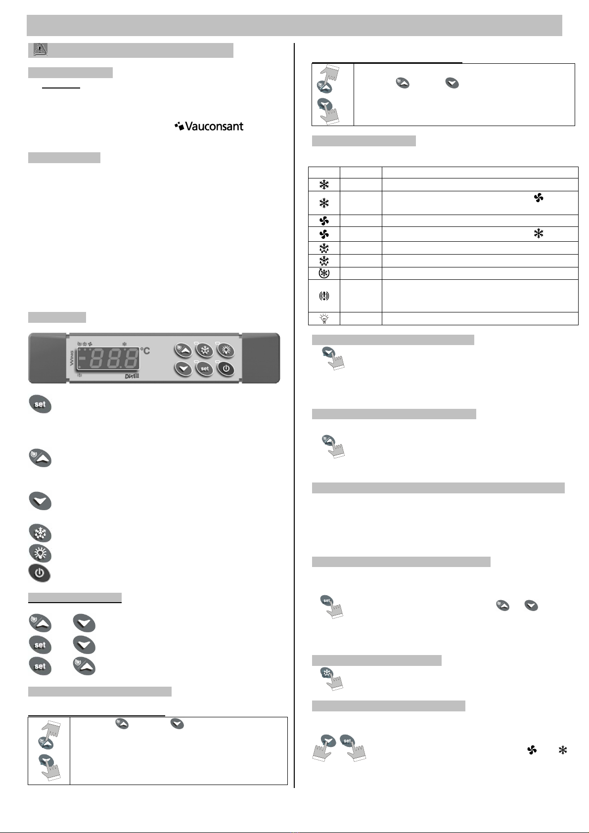
3.KEYBOARD
To display and modify target set point; in
programming mode it selects a parameter or confirm
an operation.
By holding it pressed for 3s when max or min
temperature is displayed it will be erased.
To see the max. stored temperature; in programming
mode it browses the parameter codes or increases the
displayed value. By holding it pressed for 3s the fast
freezing cycle is started.
To see the min stored temperature; in programming
mode it browses the parameter codes or decreases the
displayed value.
By holding it pressed for 3s the defrost is started.
Switch ON and OFF the light of the cold room.
Switch ON and OFF the instrument.
KEY COMBINATIONS
+
To lock and unlock the keyboard.
+
To enter the programming mode.
+
To it the programming mode.
3.1 To lock a d u lock the keyboard
HOW TO LOCK THE KEYBOARD
Keep the and the keys together for more
than 3 s. The "POF" message will be displayed and
the keyboard is locked. At this point it is only
possible the viewing of the set point or the MAX or
Min temperature stored and to switch ON and OFF
the light, the auxilary output and the instrument.
HOW TO UNLOCK THE KEYBOARD
Keep the and the keys pressed together for
more than 3 s. The "POn" message will be displayed
and the keyboard is unlocked.
3.2 Mea i g of the LED
Each LED function is described in the following table :
LED MODE FONCTION
ON The compressor is running
Flashing Programmation phase ( flashing with )
Anti short cycle delay enabled
ON The fan is running.
Flashing Programmation phase ( flashing with )
ON The defrost is enabled.
Flashing Drip time in progress
ON The fast freezing cycle is enable
ON
Alarm signal
In “Pr2” indicates that the parameter is also
present in “Pr1
ON The light is on
3.3 How to see the mi temperature
Press and release the key.
The “Lo” message will be displayed followed by the
minimum temperature recorded.
By pressing the key or waiting for 5s the normal
display will be restored.
3.4 How to see the max temperature
Press and release the o key.
The “Hi” message will be displayed followed by the
maximum temperature recorded.
By pressing the o key or waiting for 5s the normal
display will be restored.
3.5 How to reset the max a d mi temperature recorded
To reset the stored temperature, when max or min
temperature is displayed, press SET key until “rST” label starts
blinking.
N.B. : After the i stallatio RESET the temperature
stored .
3.6 How to see a d modify the set poi t
Push and immediately release the SET key: the
display will show the Set point value.
The SET LED start blinking.
To change the Set value push the or arrows
within 10s.
To memorise the new set point value push the SET
key again or wait 10s.
3.7 To start a ma ual defrost
Push the DEF key for more than 2 seconds and a
manual defrost will start.
3.8 To e ter i parameters list Pr1
To enter the parameter list “Pr1” (user accessible parameters)
operate as follows:
Enter the Programming mode by pressing the
Set and DOWN key for few seconds ( and
start blinking).
The instrument will show the first parameter
present in “Pr1”.