manuals.online logo
Brands
  1. Home
  2. •
  3. Brands
  4. •
  5. GE
  6. •
  7. Refrigerator
  8. •
  9. GE Monogram ZICP720 User manual

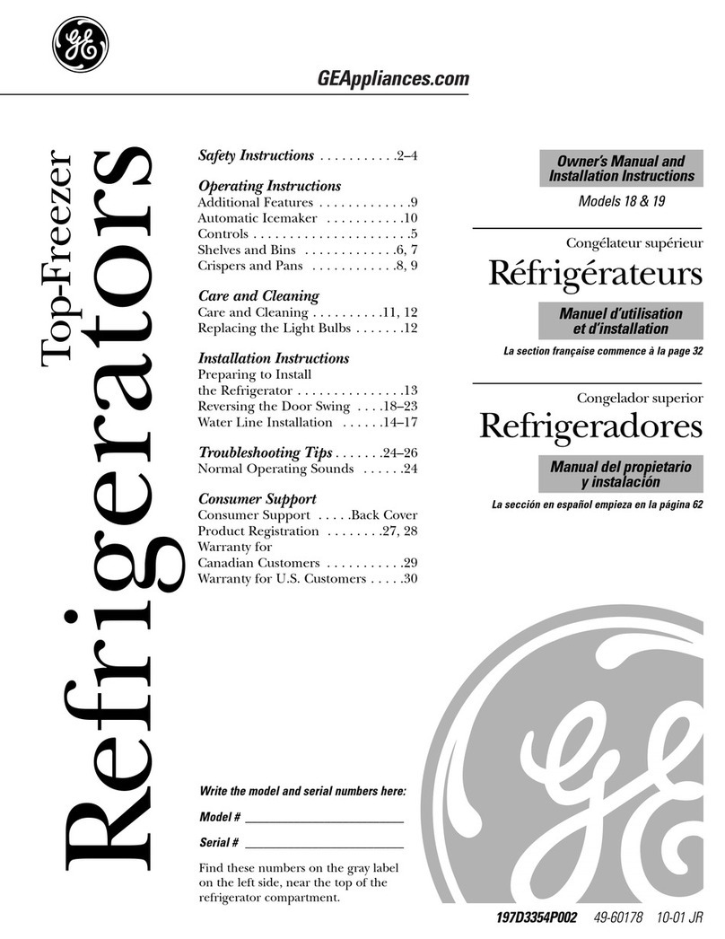
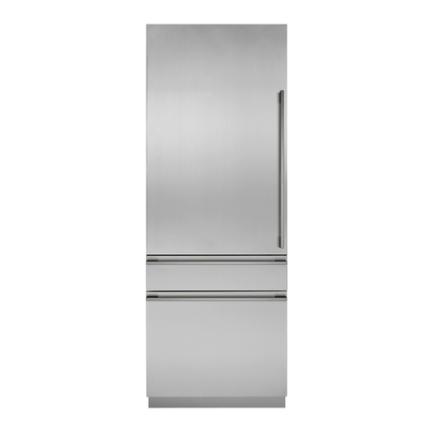
GE Monogram ZICP720 User manual

Installation
Instructions
Professional Style
Bottom-Freezer Refrigerators
ZICP720
Design Guide
With Installation Instructions
monogram.com
Safety Information
2
BEF RE Y U BEGIN
Read these instructions completely and carefully.
• IMP RTANT —Save these instructions for
local inspector’s use. Observe all governing codes and
ordinances.
• Note to Installer —Be sure to leave these instructions
with the Consu er.
• Note to Consumer —Keep these instructions with your
Owner’s Manual for future reference.
WARNING:
This appliance ust be properly grounded. See “Grounding
the Refrigerator,” page 6.
AVERTISSEMENT :
Cet appareil doit être correcte ent is à la terre.
Consultez « Mise à la terre du réfrigérateur », page 6.
If you received a da aged refrigerator, you should
i ediately contact your dealer or builder.
CAUTI N:
Due to the weight and size of these refrigerators, and to
reduce the risk of personal injury or da age to the product—
THREE PEOPLE ARE REQUIRED FOR PROPER INSTALLATION.
PRUDENCE :
À cause du poids et de la taille de ces réfrigérateurs et pour réduire
le risque de blessure et de do ages, IL FAUT TROIS PERSONNES
POUR FAIRE L’INSTALLATION CORRECTEMENT.
Skill Level —Installation of these refrigerators requires
basic echanical, carpentry and plu bing skills. Proper
installation is the responsibility of the installer. Product
failure due to i proper installation is not covered under
the GE Appliance Warranty. See the Owner’s Manual for
warranty infor ation.
WARNING:
• These refrigerators are top-heavy and ust be secured
to prevent the possibility of tipping forward. Anti-Tip
protection is required. See pages 9 and 12 for details.
• Use this appliance only for its intended purpose.
• I ediately repair or replace electric service cords that
beco e frayed or da aged.
• Unplug the refrigerator before cleaning or aking repairs.
• Repairs should be ade by a qualified service technician.
AVERTISSEMENT :
• Ces réfrigérateurs sont lourds en haut et il faut les
arri er pour éviter leur bascule ent. Il faut avoir un
systè e de protection contre le renverse ent. Voir
les détails pages 9 et 12.
• Il ne faut utiliser cet appareil que pour l’utilisation
appropriée.
• Réparez ou re placez i édiate ent tout cordon
électrique effiloché ou endo agé.
• Il faut débrancher le réfrigérateur avant le nettoyage
ou toute intervention.
• Les réparations doivent être faites par un technicien qualifié.
For Monogram local service in your area,
call 1.800.444.1845.
For Monogram service in Canada, call 1.800.561.3344
For Monogram Parts and Accessories, call 1.800.626.2002.
www. monogram.com
C NTENTS
Planning Guide
The Installation Space ......................3
Di ensions and Clearances ..........3
130° Door Swing..................................4
90° Door Swing ....................................5
Installation Instructions
Tools, Hardware, Tri ,
Materials, Flooring ..............................6
Grounding the Refrigerator ............6
Step 1, Re ove Packaging ............7
Step 2, Install Water Lines ..............7
Step 3, Install New Side Tri ..........8
Step 4, Install Side Panels................8
Step 5, Install Anti-Tip Brackets....9
Step 6, Position Refrigerator
and Install Top Tri ..........10
Step 7, Level the Refrigerators ..11
Step 8, Alternate Anti-Tip
Procedure..............................12
Step 9, Secure Refrigerator
to Cabinetry ........................12
Step 10, Install Grille Panel ..........12
Step 11, Install Center
Tri Strip ............................13
Step 12, Adjust Door Swing..........13
Step 13, Check and Correct
Door Align ent ..............14
Step 14, Install Grille Base Wrap....17
Step 15, Connect Water Supply ..17
Step 16, Connect Power ................18
Step 17, Start Ice aker ................18
Step 18, Install Toekick ..................18
DIMENSI NS AND CLEARANCES
Product Clearances
These refrigerators are equipped with a 2-position
door stop. The factory set 130° door swing can be
adjusted to 90° if clearance to adjacent cabinets
or walls is restricted.
Allow 25″ini u clearance for a full 130° door
swing. Allow 15″for pan re oval.
5″ini u clearance is required when door swing
is adjusted to 90°. If the 90° door stop position is
used, pan access is aintained, but pan re oval
is restricted.
See illustrations on pages
4 and 5 to deter ine door
swing interaction with
adjacent cabinets or
countertops.
Design Guide
THE INSTALLATI N SPACE
The installation space ust be 71-1/2″.
Water And Electrical Locations
Electrical and water supply ust be located
as shown.
The cutout depth must be 24″
The refrigerator will project forward, slightly
beyond adjacent cabinetry, depending on your
installation.
Cutout depth beneath a soffit:
When installed beneath a soffit, the soffit cannot
exceed the 24″installation depth shown. The top
case tri overlaps the botto of the soffit.
Additional Specifications
•A separate 115 volt 60Hz., 15 or 20 a p power
supply is reco ended for each product. An
individual properly grounded branch circuit or
circuit breaker is reco ended. Install properly
grounded 3-prong electrical receptacles recessed
into the back wall. Electrical ust be located on
rear wall as shown.
N TE: GFI (ground fault interrupter) is not
reco ended.
• Both water lines can enter the opening through
the floor or back wall. Route GE S artConnect™
kit or 1/4″O.D. copper tubing between the cold
water line and the water connection location.
The tubing should be long enough to extend to
the front of the refrigerator. Installation of an
easily accessible shut-off valve in the water
line is required.
2-5/16"
75" From
Floor to Bottom
of Electrical Are
a
84-1/2" max
83-1/2" min
Finished
Opening
71-1/2" Finished Width
Electrical
24" Cutout Depth
Wall View
24-3/16"
6"
10"
6"
10"
5"
10" 10"
Water Supply
3-1/2" 3-1/2" 3-1/2" 3-1/2"
5"
3-1/2"
5"
10"
5"
3-1/2"
90° Door
Swing
* Shipping height. The
refrigerators can be
adjusted to fit into a
cutout that is 83-1/2″
min. to 84-1/2″max.
Note that the top case
trim at the front is 1/2″
higher and will overlap
upper cabinetry or
soffit. Use leveling legs
and wheels for a
maximum 1″height
adjustment.
83-1/2″
at Rear
28-11/16″
Depth Including
Handles
72″Frame
to Frame
Width
84″
71-1/2″
Case Width 25-3/4″
Case Depth
130° Door
Swing
130° Door
Swing
36-3/4″
90°
5″Minimum to
Wall
3
71-1/2″Finished Width
2-5/16″
Electrical 24-3/16″
6″6″
10″
Wall View
10″
5″
10″
10″
75″From
Finished Floor
to Bottom of
Electrical Area
3-1/2″
Water Supply
3-1/2″
84-1/2″max
83-1/2″min
Finished
Opening
24″Cutout Depth
0″
25″
Min. to
Wall
25″
Min. to
Wall
23-7/8″
Behind
Frame
3-1/2″
10″
3-1/2″3-1/2″
3-1/2″
5″
5″
5″
1/4" 1/2" 3/4" 1" 1-1/4"
1"
3/4" Overlay
Panel
(Nominal Size)
Stainless Steel
1/4"
1/2"
3/4"
2"
1-1/4"
1-1/2"
1-3/4"
3"
2-1/4"
2-1/2"
2-3/4"
1/4"
1/2"
3/4"
Door
23-7/8" From
Rear of
Refrigerator
1"
Refrigerator
Case
Trim
Top View
130° D R SWING
(factory setting)
Scale 1:1
4
Frameless Cabinets: The case tri
overlaps cabinets at the top and sides.
Therefore, fra eless cabinets ay require
filler strips to prevent interference with
cabinet door swing. The opening ust
allow for filler strips.
Design Guide
1/4"
1/2"
3/4"
1"
1-1/4"
1/4"
1/2"
3/4"
1"
1-1/4"
1-1/2"
23-7/8"
From Rear of
Refrigerator
3/4" Overlay
Panel
(Nominal Size)
Case Trim
Refrigerator
Door
Stainless Steel
5
Top View
90° D R SWING
(optional setting)
Scale 1:1
Frameless Cabinets: The
case tri overlaps cabinets
at the top and sides.
Therefore, fra eless
cabinets ay require
filler strips to prevent
interference with cabinet
door swing. The opening
ust allow for filler strips.
Design Guide
T LS REQUIRED
• Tinsnips to cut banding
• Stepladder
• Bucket
• Level
• Appliance dolly
• Tubing cutter
• 7/16″open-end wrench
• #2 Phillips screwdriver
• Drill and appropriate bits
• 5/16″, 7/16″socket
• Safety glasses
• 1-1/4″and 1/2″open-ended wrench
• Pliers
• 1/4″ratchet or 1/4″angled wrench
• Tape easure
HARDWARE SUPPLIED
• Water filter bypass plug
• Anti-Tip brackets
• 1/4″nut and ferrule
TRIM SUPPLIED
A. Top tri
B. Left inside case tri
C. Right inside case tri
D. Center U-shape tri
E. Grille base wrap
F. Grille panel
G. Toekick
H. Foa spacer pads
I. Phillips screws (34)
J. Package of 12 plastic spacers
K. Flat etal bracket
L. 2 Large screws (for etal bracket)
M. 2 Corner tri brackets
MATERIALS REQUIRED
• 71″long 2x4 for Anti-Tip support
• 1/4″copper water line tubing or two GE
S artConnect™Refrigerator Tubing kits
• Two water shut-off valves
• Screws to secure refrigerator to cabinetry
• Stick-on hook and loop fastener strips for 1/4″
side panels
FL RING
For proper installation, this refrigerator ust be
placed on a level surface of hard aterial that is at
the sa e height as the rest of the flooring. This
surface should be strong enough to support a fully
loaded refrigerator, or approxi ately 2,400 lbs.
N TE: Protect the finish of the flooring. Cut a large
section of the cardboard carton and place under the
refrigerator where you are working.
GR UNDING THE REFRIGERAT R
IMP RTANT—(Please read carefully)
FOR PERSONAL SAFETY, THIS APPLIANCE MUST BE
PROPERLY GROUNDED.
The power cord of this appliance is equipped with
a 3-prong (grounding) plug which ates with a
standard three-prong (grounding) wall receptacle
to ini ize the possibility of electric shock hazard
fro this appliance.
Have the wall outlet and circuit checked by a
qualified electrician to ake sure the outlet is
properly grounded.
Where a standard 2-prong wall outlet is encountered,
it is your personal responsibility and obligation to
have it replaced with a properly grounded 3-prong
wall outlet.
DO NOT, UNDER ANY
CIRCUMSTANCES, CUT
OR REMOVE THE THIRD
(GROUND) PRONG FROM
THE POWER CORD.
DO NOT USE AN ADAPTER PLUG TO CONNECT THE
REFRIGERATOR TO A 2-PRONG OUTLET.
DO NOT USE AN EXTENSION CORD WITH THIS
APPLIANCE.
6
Installation Instructions
A
B
C
D
E
F
G
K
I
J
H
M
L
7
Installation Instructions
REM VE PACKAGING
CAUTI N: Refrigerator is uch heavier at the top than at
the botto —be careful when oving. When using a hand truck,
handle fro side only.
PRUDENCE : Le réfrigérateur est beaucoup plus lourd
en haut qu'en bas. Il faut être prudent lors des déplace ents.
Si un diable est utilisé, il faut soulever le réfrigérateur sur le côté
seule ent.
• Carefully cut banding at the top and botto , re ove outer
carton.
• Slide out back corner posts (2).
• Slide carton off top of cabinet.
N TE: IT IS NOT NECESSARY TO LAY CABINET DOWN IN ORDER
TO REMOVE SKID!
• The unit is secured to the skid with 4 slotted tie-down straps.
Re ove the four 5/16″bolts fro the base channels in the
tie-downs.
• Re ove the four 7/16″
bolts securing the straps
to the skid.
CAUTI N: DO NOT
ATTEMPT TO ROLL UNIT
OFF SKID.
PRUDENCE :
IL NE FAUT PAS ESSAYER
DE FAIRE ROULER LE
RÉFRIGÉRATEUR POUR
L'ENLEVER DE LAY PALETTE.
• Support blocks on the botto of the refrigeration case ust
be re oved before the refrigerator is taken off the skid or
da age will occur. Carefully tilt refrigerator and slide blocks
out fro beneath.
• Re ove the tape fro the leveling legs.
• Lift the refrigerator off the skid with an appliance dolly.
Handle fro the sides.
1
Remove
Tie-Downs
INSTALL WATER LINES
• A cold water supply is required for auto atic ice aker
operation. The water pressure ust be between 40 and 120
p.s.i.
• Route 1/4″OD copper or GE S artConnect™plastic tubing
between house cold water line and the water connection
location.
• Tubing should be long enough to extend to the front of the
refrigerator. Allow enough tubing to acco odate bend
leading into the water line connection.
N TE: The only GE approved plastic tubing is supplied in
the GE S artConnect™Refrigerator Tubing kits. Do not use
any other plastic water supply line because the line is under
pressure at all ti es. Other types of plastic ay crack or
rupture with age and cause water da age to your ho e.
GE S artConnect™Refrigerator Tubing Kits are available in the
following lengths:
2′(.6 ) WX08X10002
6′(1.8 ) WX08X10006
15′(4.6 ) WX08X10015
25′(7.6 ) WX08X10025
Shut off the main water supply.
Turn on the nearest faucet long enough to clear the line of
water.
• Install a shut-off valve between the ice aker water valve and
cold water pipe in a base ent or cabinet. The shut-off valve
should be located where it will be easily accessible.
• Turn on the ain water supply and flush debris.
Run about a quart of water through the tubing into
a bucket. Shut off water supply at the shut-off valve.
N TE: Saddle type shut-off valves are included in any water
supply kits. Before purchasing, ake sure a saddle type valve
co plies with your local plu bing codes.
If the water supply to the refrigerator is from a Reverse
smosis Water System, use the refrigerator’s filter bypass
plug. Using the refrigerator’s water filtration cartridge with
the R filter can result in hollow ice cubes.
2
N TE: Co onwealth of Massachusetts Plu bing Codes
248CMR shall be adhered to. Saddle valves are illegal and use
is not per itted in Massachusetts. Consult with your licensed
plu ber.
Floor
Filter Bypass Plug
Waterline Tubing
INSTALL SIDE PANELS
Side panels ust be used whenever the sides
of the refrigerator will be exposed. The 1/4″
side panels will slip into the side case tri .
Secure the panels to the refrigerator with
stick-on hook and loop fastener strips. Order
the side panels fro the cabinet anufacturer.
• Cut a notch in the top front corner as shown
to allow clearance for corner keys in the front
side tri .
Skip this step if you are not using side panels.
4
INSTALL NEW SIDE TRIM
CAUTI N: Handle parts with care to avoid
scratching.
PRUDENCE : Manipulez les pièces
soigneuse ent pour éviter de les rayer.
A. Install inside case tri s (B & C) with notches
toward the botto . Install screws (I) through 5 slots
on each tri .
B. Apply the supplied foa spacer pads (H) to the
ating side of one product as shown.
3
8
* Depending on
installation height.
Installation Instructions
Foam Spacer
Pads
24″
*84″
3/16″
1-7/8″
*3″to 4″
2-9/16″
INSTALL ANTI-TIP BRACKETS
WARNING: ANTI-TIP PRECAUTI NS
These refrigerators are top-heavy and ust be
secured to prevent the possibility of tipping forward.
ATTENTI N : PRECAUTI NS C NTRE LES
BASCULEMENTS
Ces réfrigérateurs sont beaucoup plus lourds
en haut et il faut les aintenir en place pour éviter
la possibilité de son bascule ent vers l’avant.
• Cut a 2″x 4″x 71″block and secure the block to the
ounting brackets provided using #12 or #14 wood
screws.
• Secure the bracket with wood block to the back wall
so that it is 84″(or your installation height) fro the
finished floor. Use #12 or #14 wood screws. See
illustration.
• Screws ust penetrate at least one inch into vertical
wall studs.
IMP RTANT N TE: When the refrigerator is installed
under a soffit or if there is not enough height for this
ethod of security, brackets cannot be used. Step 8 is
an alternate anti-tip procedure to secure refrigerator
to cabinets after it has been pushed into the final
position. The refrigerator ust be secured to prevent
tipping.
5
9
Installation Instructions
2 x 4 Cut
71″Length
Installation Height
From Floor
Screws Mounted into
Vertical Wall Studs
Mounting
Bracket
Brackets
Required
Brackets
Not Required
Beneath a
Soffit
Height
From
Floor to
Bottom
of
Wood
Block
Side View
Block Soffit
P SITI N REFRIGERAT R
AND INSTALL T P TRIM
• Before pushing the refrigerators into the
opening, plug the power cords into the
receptacles. Reach into the top opening
to grasp the power cord. Pull the power
cord into the opening as you push the
refrigerator back.
• With hands against front corners,
push one refrigerator part-way into
the opening. The refrigerator should
be approxi ately 8″forward of the
back wall.
• Gently push the second refrigerator
next to the other. The doors should be flush to each
other and the inside tri s together.
• Install corner bracket (M) into each side of the
top tri (A).
• Place the top tri across the top of the refrigerators
and slip the corner brackets into the outside case
tri s.
• Install 8 screws (I) through the top of the tri and
into the top case.
• Check to be sure the inside tri s are aligned top
and botto . There should be a slight gap between
the case tri s.
• Install the flat etal bracket (K) between the two
achine co part ents. Slip the bracket under the
inside tri . Secure the bracket using the larger screws
(L), one on each side. Leave a 3/8″gap between the
screw head and the top surface of the bracket.
PUSH REFRIGERAT R INT PENING
N TE: 2 PEOPLE ARE REQUIRED TO PUSH THE UNIFIED
REFRIGERATORS INTO THE OPENING.
• With hands against the front corners, gently push
the unified refrigerators into the opening or against
the back wall.
6
10
Installation Instructions
Soffit
Approx. 8″
Corner Trim
Bracket
Drive screws
leaving a
3/8″gap
Slide bracket
beneath trim
11
Installation Instructions
LEVEL THE REFRIGERAT RS
Place a level inside the achine for each unit.
Both refrigerators MUST BE LEVEL AND PLUMB with
each other and with adjacent cabinetry on each side.
Drawers should be evenly aligned.
Both refrigerators have 4-point leveling. The front is
supported by leveling legs, the rear is supported by
adjustable wheels. Both are accessible fro the front
of the refrigerator.
• To level the back of the refrigerator, turn the 7/16″hex
nut located above the front wheels. Turn clockwise to
raise or counterclockwise to lower the refrigerator.
• For front leveling, use a 1-1/4″open-end wrench.
• Adjust height of refrigerator to atch installation cutout
opening 83-1/2″to 84-1/2″. The refrigerator should be
level and plu b with cabinetry.
• When refrigerators are level, tighten screws against the
bracket.
CAUTI N:
The rear leveling wheels and front leveling legs are li ited
to a axi u height adjust ent of 1″. If the installation
requires ore than 84-1/2″height, the installer should
elevate the refrigerator on a sheet of plywood or runners.
Cabinetry tri could also be added across the top of the
opening to shorten the opening. If you attempt to raise
the refrigerator more than 1″, you will damage the
front leveling legs and the rear leveling wheels.
PRUDENCE :
Les roues de nivelle ent arrière et les pattes de
nivelle ent avant per ettent un réglage axi al de
25 (1 po). Si l’ouverture pour le réfrigérateur a une
hauteur supérieure à 2,15 (84-1/2 po), l’installateur doit
élever le réfrigérateur sur une feuille de contre-
plaqué ou
des glissières. Il est égale ent possible d’ajouter des baguettes
de finition des placards sur le haut de l’ouverture afin de
la réduire. Lever le réfrigérateur de plus de 25 mm (1 po)
endommage les pattes de nivellement avant et les roues
de nivellement arrière.
7
Leveling
Leg
Hex Nut Adjusts
Rear Wheels
Tighten bracket
screws
12
Installation Instructions
SECURE REFRIGERAT R T CABINETRY
Whenever possible, perfor this step for anti-tip
security, or when anti-tip brackets cannot be used.
The refrigerator must be secured to prevent tipping.
• Drill hole in tri and drive screw through the tri
into adjacent cabinet.
• Follow the sa e procedure on the opposite side.
9
ALTERNATE ANTI-TIP PR CEDURE
The refrigerator must be secured to prevent tipping.
The anti-tip brackets cannot be used on metal
wall studs. Use this Alternate Procedure to secure
the refrigerator against tip-over whenever metal wall
studs are encountered and there is a soffit.
• Use a 3/16″bit to drill eight evenly spaced clearance
holes through the etal top case tri .
• Use a 1/16″bit to drill pilot holes through the etal
clearance holes and into the wood soffit. The holes
should be centered in the soffit or a 3/4″in. wood
brace. The brace spanning the enclosure ust be
securely fastened to cabinets on both sides.
• Install eight (4 on each refrigerator) 1-1/2″drywall
screws into the pilot holes.
8
Top Case Trim
Install Eight 1-1/2″Drywall Screws Through Trim
and Into Soffit or 3/4″Min. Wood Brace
3/4″
Min.
Side View
Top Case Trim
Drive Screws Through Case Trim
and Into Adjacent Cabinets
Top Case Trim
INSTALL GRILLE PANEL
TW PE PLE ARE REQUIRED T INSTALL
THE GRILLE PANEL.
• Push all four hinges on the grille panel (F) to the
open position.
• Hold the unified grille panel against the left side of the
opening. Drive 2 screws through the hinge and into the
support bracket. Install the right side hinge. Then install
the center hinges.
• Grasp grille panel at the center and pull down to close.
The panel should align evenly with the beveled side
of the door.
N TE: To adjust the grille panel backward or forward,
loosen the 2 attach ent screws on all 4 hinges. Slide
the grille panel outward or to the back. Tighten the screws.
10
Install 2
screws
Grille Panel
INSTALL CENTER TRIM STRIP
• Open doors fully.
• The case tri s should be evenly aligned top to
botto with a slight gap between the .
• Starting at the top, press center tri strip (D) over the
inside case tri s of both refrigerators.
• Continue pressing tri until you reach the botto of
the case tri s. The tri should align with the top and
botto of case tri s.
11
13
Installation Instructions
Case Trim
U-Shape
Trim
ADJUST D R SWING
N TE: This refrigerator has a 2-position door stop.
When space does not allow the door to swing open
fully to 130°, you ay change the door swing to
a 90° opening. Skip this step if door opening is
satisfactory for your installation situation.
• Lift the grille panel to access the door stop.
• Use pliers to unscrew door stop and reinstall
into the 90° position.
12
Pin Location
For 90°
Door Swing
Pin Location
as Shipped
For 130°
Door Swing
14
Installation Instructions
CHECK AND C RRECT D R ALIGNMENT
13
• Close the grille panel and both doors.
• Check that the freezer drawers and botto of doors
are horizontal and even at the lower inside corners.
• Carefully easure the inside corners to deter ine
if an adjust ent is needed. A difference of 1/32″is
acceptable and does not require adjust ent.
SKIP THIS STEP IF D RS ARE LEVEL.
IMP RTANT: If the doors are not evenly aligned,
they ust be re oved and spacers ust be installed
to raise or lower both doors.
Spacer
Location Spacer
Location
CHECK AND C RRECT D R ALIGNMENT (cont.)
13
CAUTI N: Follow instructions very carefully.
PRUDENCE : Suivez les instructions très
soigneuse ent.
DETERMINE C RRECT SPACER
This kit contains 12 plastic spacers (2 of each size). Match
spacer to illustration below to be sure you have selected
the correct size as deter ined in the charts below.
LH Fresh Food door is higher than the RH door:
Select the correct spacers to install on the Fresh Food
hinges as deter ined by Di ension A.
LH Door Install Install
Dim. A LH Spacer RH Spacer
1/32″to 1/16″3/32″1/4″
1/16″to 3/32″3/16″1/4″
3/32″to 1/8″5/32″1/4″
1/8″to 5/32″1/8″1/4″
5/32″to 3/16″1/8″9/32″
3/16″to 7/32″1/4″9/32″
RH Fresh Food door is higher than the LH door:
Select the correct spacers to install on the Fresh Food
hinges as deter ined by Di ension A.
RH Door Install Install
Dim. A LH Spacer RH Spacer
1/32″to 1/16″1/4″3/32″
1/16″to 3/32″1/4″3/16″
3/32″to 1/8″1/4″5/32″
1/8″to 5/32″1/4″1/8″
5/32″to 3/16″9/32″1/8″
3/16″to 7/32″9/32″3/32″
N TE: If this plastic spacer package is isplaced,
order WR49X10162 for a replace ent kit.
15
3/32″
5/32″
1/4″
1/8″
3/16″
9/32″
Dimension
A
Dimension
A
Installation Instructions
16
Installation Instructions
CHECK AND C RRECT D R ALIGNMENT (cont.)
13
1. Open the grille panel.
2. Re ove 4 screws on the hinge plate.
3. Use pliers to re ove door stop pin.
4. Lift door off botto hinge pin. The door ust be held
in place while spacers are being exchanged.
5. Re ove the original plastic spacer.
6. Place the selected spacer over the hinge.
7. Reverse all steps to replace the door.
Remove
Pin
Remove
4 Screws
Lift off and replace
plastic spacer
INSTALL GRILLE BASE WRAP
• Open doors fully. Open the grille panel.
• Install the unified double width grille base wrap (E)
by slipping the notched ends over the door hinges.
• Install one screw (I) on each end and 2 at the center.
14
17
Installation Instructions
C NNECT WATER SUPPLY
15
• Locate and bring tubing to the front of the cabinet.
• Turn the water on to flush debris fro line. Run
about a quart of water through tubing into a
bucket, then shut off water.
Copper Tubing:
• Slip a 1/4″nut and ferrule (provided) over both
ends of the copper tubing. Insert tube into the
union fitting on the unit and tighten nut to union.
• Turn on the water to check for leaks.
GE SmartConnect™Tubing:
• Insert the olded end of the tubing into the
refrigerator connection. Tighten the co pression
nut until it is just hand tight.
• Tighten one additional turn with a wrench.
Overtightening can cause leaks!
• Turn on the water to check for leaks.
N TE: Make sure excess tubing length does not
interfere with drawer closing or toekick installation.
Connect both refrigerators to the water supply.
House
Water Supply Refrigerator
Water Supply
Unified Grille Base Wrap
Place Trim
Over Hinges
18
Installation Instructions
C NNECT P WER
• Check to be sure the power cord is plugged
into the receptacle.
• Check to ake sure power to refrigerator is on
by opening refrigerator door to see if interior
lights are on.
• The te perature controls are preset at 37°F
for the fresh food section and 0°F for the freezer.
• Allow 24 hours for te perature to stabilize
before aking adjust ents.
16
START ICEMAKER
• Flip the switch to I ( N). The ice aker will begin
operation auto atically.
• Be sure nothing interferes with the sweep of the
feeler ar .
• Discard the first full bucket of ice cubes.
• To turn the ice aker off, set the switch to ( FF).
17
INSTALL T EKICK
• Install the toekick (G) with 4 screws (I) provided,
one on each side and 2 in the center.
IMP RTANT: The toekick ust be positioned with
the vented slots on the top side. The vented toekick
ust re ain unobstructed for proper air circulation
and refrigerator operation.
18
Electrical
Outlet Master Light
Switch
Raise
Grille
Panel
Power Switch
Feeler Arm
19
Notes
49-60469-2
224D1234P001
09-07 JR
Printed in the United States
N TE: While perfor ing installations described in this book,
safety glasses or goggles should be worn.
If your Monogram appliance should ever require
service, you can depend on Monogram Preferred
Service. Simply call 1.800.444.1845 here our
Monogram Preferred Service Specialists are available
7 a.m. to 10 p.m. ET Monday through Friday and
8 a.m. to 6 p.m. ET Saturday and Sunday to
coordinate your service appointment.
N TE: Product i prove ent is a continuing endeavor
at General Electric. Therefore, aterials, appearance
and specifications are subject to change without notice.
GE Consumer & Industrial
Appliances
General Electric Co pany
Louisville, KY 40225
ge.co

Other manuals for Monogram ZICP720

2

Other GE Refrigerator manuals

GE Side by Side Refrigerators User manual

GE

GE Side by Side Refrigerators User manual

GE GTR10 Operating instructions

GE

GE GTR10 Operating instructions

GE GDE20GMHBRES Operating instructions

GE

GE GDE20GMHBRES Operating instructions

GE CYE22TSHBSS Operating instructions

GE

GE CYE22TSHBSS Operating instructions

GE Profile 200D8074P009 User manual

GE

GE Profile 200D8074P009 User manual

GE Profile PGSS5NFZSS Assembly instructions

GE

GE Profile PGSS5NFZSS Assembly instructions

GE GTR11AAPR User manual

GE

GE GTR11AAPR User manual

GE GE Profile Arctica PSS27NHN User instructions

GE

GE GE Profile Arctica PSS27NHN User instructions

GE GTS18SHSSS Manual

GE

GE GTS18SHSSS Manual

GE PSI23NCR - Profile 22.6 cu. Ft Manual

GE

GE PSI23NCR - Profile 22.6 cu. Ft Manual

GE CTT14CYT Training manual

GE

GE CTT14CYT Training manual

GE GTS18ABBRWW Assembly instructions

GE

GE GTS18ABBRWW Assembly instructions

GE GTL22JCPBS Manual

GE

GE GTL22JCPBS Manual

GE r10965v-1 User manual

GE

GE r10965v-1 User manual

GE GBC12 and Operating instructions

GE

GE GBC12 and Operating instructions

GE GE Profile CustomStyle Energy Star PSW23PSS Manual

GE

GE GE Profile CustomStyle Energy Star PSW23PSS Manual

GE 197D8622P005 User manual

GE

GE 197D8622P005 User manual

GE GTL21KCXBS - R 21.0 Cu. Ft. Top-Freezer... Manual

GE

GE GTL21KCXBS - R 21.0 Cu. Ft. Top-Freezer... Manual

GE GSL22JFX User manual

GE

GE GSL22JFX User manual

GE PSHS6VGX - Profile: 25.5 cu. Ft.... User manual

GE

GE PSHS6VGX - Profile: 25.5 cu. Ft.... User manual

GE GE Profile Arctica CustomStyle PSC23SHN User instructions

GE

GE GE Profile Arctica CustomStyle PSC23SHN User instructions

GE Profile 42 Operating instructions

GE

GE Profile 42 Operating instructions

GE GTR10GBEWW Assembly instructions

GE

GE GTR10GBEWW Assembly instructions

GE 16 Series Original instructions

GE

GE 16 Series Original instructions

Popular Refrigerator manuals by other brands

Beko RCNE520E31DZM user guide

Beko

Beko RCNE520E31DZM user guide

Zanussi ZDC 75-4 Instruction booklet

Zanussi

Zanussi ZDC 75-4 Instruction booklet

Whirlpool GC5NHAXVQ00 parts manual

Whirlpool

Whirlpool GC5NHAXVQ00 parts manual

Frigidaire FRT18KS5A Factory parts catalog

Frigidaire

Frigidaire FRT18KS5A Factory parts catalog

Hitachi R-Z570ARU6X Use and care instructions

Hitachi

Hitachi R-Z570ARU6X Use and care instructions

Siemens KI20RA55 Instructions for use

Siemens

Siemens KI20RA55 Instructions for use

inventum KV1435S instruction manual

inventum

inventum KV1435S instruction manual

Hisense RD-39DR4SAA/CPA1 user manual

Hisense

Hisense RD-39DR4SAA/CPA1 user manual

Beko ASD241B Installation & operating instructions

Beko

Beko ASD241B Installation & operating instructions

Monogram ZIDI240 owner's manual

Monogram

Monogram ZIDI240 owner's manual

LG MFL62423829 owner's manual

LG

LG MFL62423829 owner's manual

Dometic RM 5310 installation manual

Dometic

Dometic RM 5310 installation manual

Gram Compact 1210 instruction manual

Gram

Gram Compact 1210 instruction manual

LG GMJ844PZKV owner's manual

LG

LG GMJ844PZKV owner's manual

Saivod AT75200N Instructions for use

Saivod

Saivod AT75200N Instructions for use

Sub-Zero ICB648PRO Use & care guide

Sub-Zero

Sub-Zero ICB648PRO Use & care guide

Gaggenau IK300 operating instructions

Gaggenau

Gaggenau IK300 operating instructions

Thermador T36IB902SP installation instructions

Thermador

Thermador T36IB902SP installation instructions

manuals.online logo
manuals.online logoBrands
  • About & Mission
  • Contact us
  • Privacy Policy
  • Terms and Conditions

Copyright 2025 Manuals.Online. All Rights Reserved.