www.vecima.com
© 2020 Vecima Networks Inc. All rights reserved.
rev 2020.10.14
Page 4 of 10
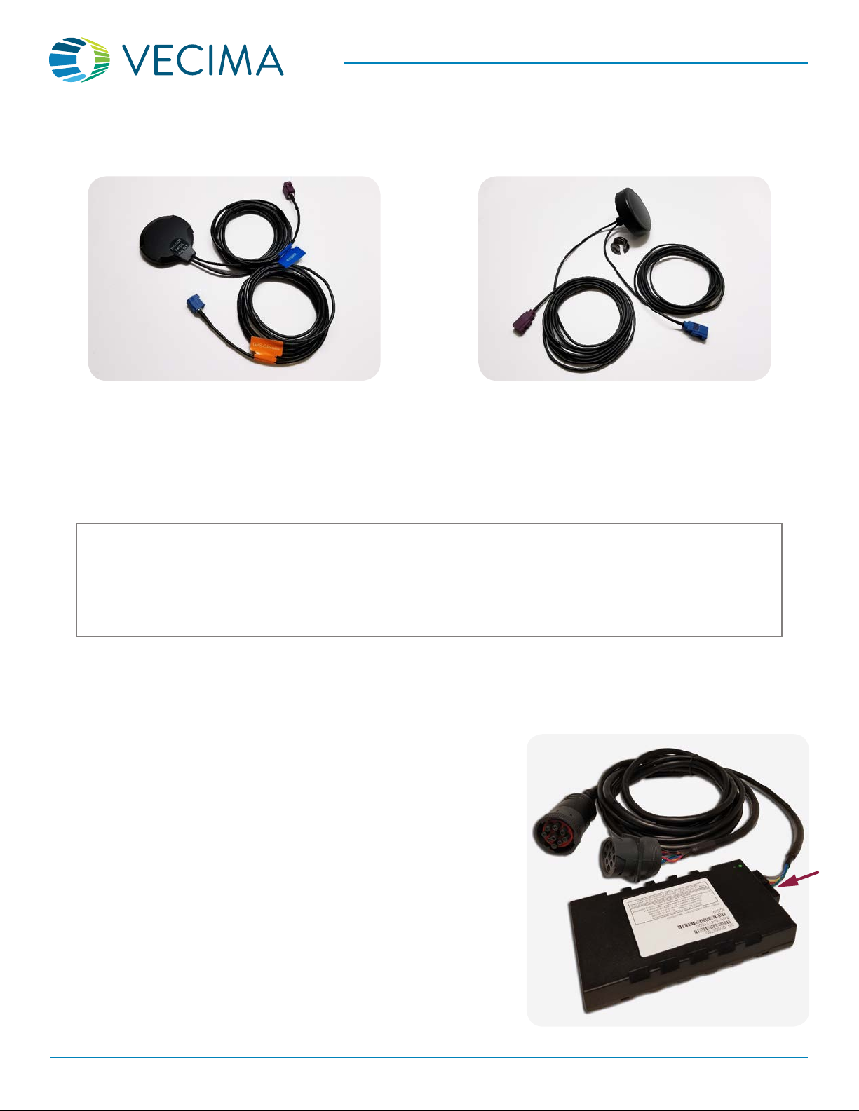
installation guideINSTALLATION GUIDE
Vecima 66xx Beacon Family
LED Indicators
The 66xx has two LEDs on the top of the device which provide feedback about the current state.
• When the ignition is rst turned on the Green indicator will show solid for about 30 seconds. After this initial setup period,
the Green LED will blink slowly (8 times in 10 seconds) when the Ignition is turned o, and rapidly (25 times in 10 seconds)
when the Ignition is turned on.
• The Red LED is used to indicate error conditions by ashing a 2-digit code. The rst digit indicates the general error type
(1=hardware, 2=modem, 3=GPS, 4=end-to-end service) and the second digit indicates a more specic error described in
the table below. Note that if multiple error conditions exist, the Red LED will cycle through all current error conditions.
RED LED Error Codes
1st Digit 2nd Digit Error Condition
1 1 License key has expired. Please contact Vecima Support.
1 2 Low supply voltage. Ensure that the vehicle battery is supplying adequate voltage.
Contact Vecima Support if the error persists.
1 3 Data usage exceeded. Please contact Vecima Support.
2 1 Modem module fault. Please contact Vecima Support.
2 2 No SIM inserted. Please contact Vecima Support.
2 3 No cellular signal. *
2 4 Network not found. Please contact Vecima Support to verify the SIM activation.
2 5 Last data session failed. *
2 6 GPRS not attached. Please verify beacon activation.
3 1 GPS module fault. Please contact Vecima Support.
3 2 GPS antenna fault. *
3 3 GPS not tracking any satellites. *
3 4 GPS no x (< 3 satellites). *
3 5 GPS has no time. *
4 2 Data transfer failed. *
* These issues may be caused
by an incorrectly positioned
beacon.
If the device is connected
properly and has an
unobstructed view of the sky,
and the error persists, please
contact Vecima Support at
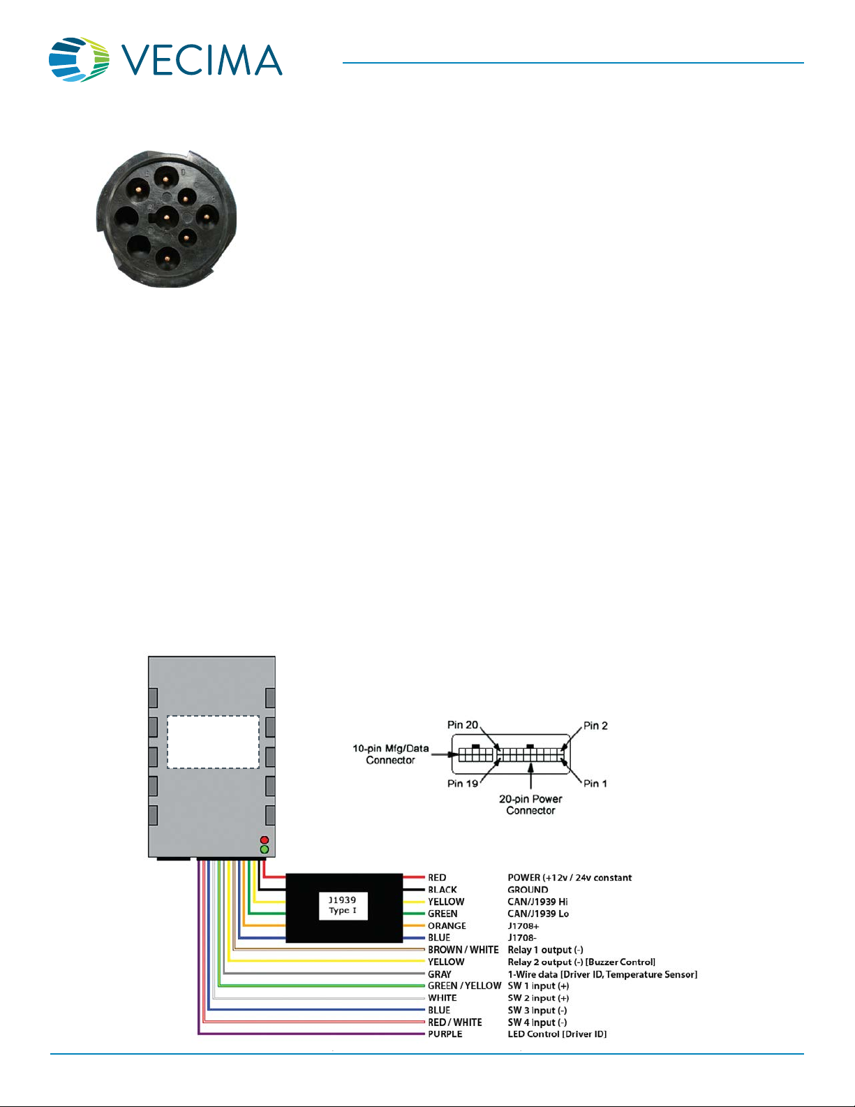
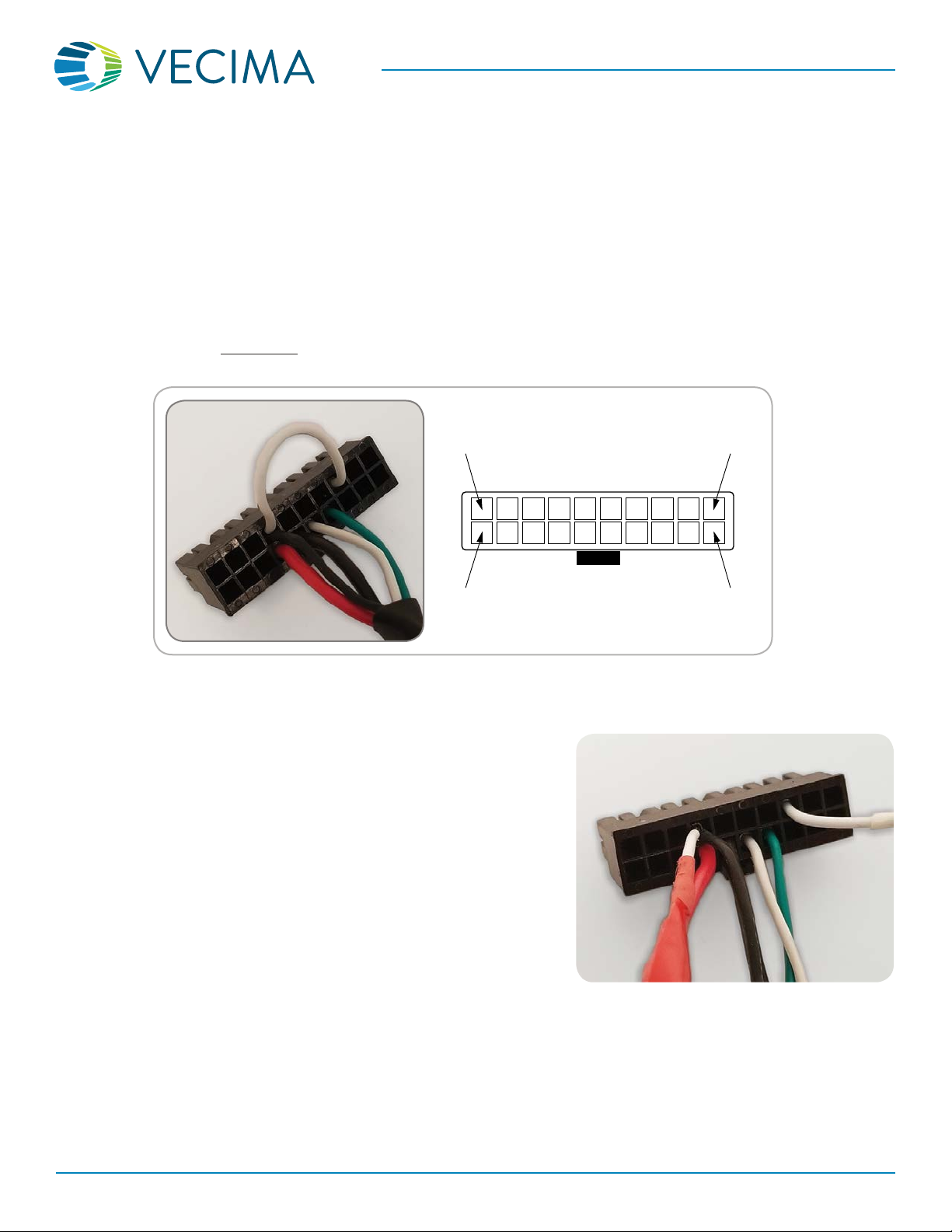
20-pin Molex Connector – Pin Descriptions
Pin Wire Color Description Pin Wire Color Description
1Black GND 11 White Switch 2 input (+)
2 Yellow Relay 2 output (-) [
Buzzer Control] 12 Yellow (J1939 cable) CAN/J1939 Hi
3 Blue (J1939 cable) J1708- 13 Red/White Switch 4 input (-)
4 Orange (J1939 cable) J1708+ 14 Green (J1939 cable) CAN/J1939 Lo
5 Blue Switch 3 input (-) 15 White Ignition input (+) [not used]
6Gray 1-Wire data [Driver ID, Sensor] 16 Brown/White Relay 1 output (-)
7 Cable ID (* see side note) 17 Black GND
8 Red (J1939 cable) Power input (+8 to +30v
constant) 18 Green/Yellow Switch 1 input (+)
9 [not used] 19 Purple LED Control [Driver ID]
10 Black (J1939 cable) Ground 20 Brown Analog input (0 – 16v)
[not used]
*This pin is not used for
the Type-1 cable, but may
be used on other cables as
an identier for the cable/
port type: +12v indicates
OBD, GND indicates J1939
500 kHz, and OPEN indicates
J1939 250 kHz.