Veeder-Root Stoneridge Tachograph Programmer User manual

Document No. 6957-193 June 2006 Revision 2.3 ©Copyright Stoneridge Electronics Ltd
Manufacturers of VEEDER-ROOT Tachographs
1
Stoneridge
Tachograph Programmer
User Manual

Document No. 6957-193 June 2006 Revision 2.3 ©Copyright Stoneridge Electronics
Ltd Manufacturers of VEEDER-ROOT Tachographs
2
1.
INTRODUCTION.............................................................................. 4
1.1
What does the Tachograph Programmer do?........................................................ 4
1.2
With which Tachograph Types can the Programmer be used ?............................. 4
1.3
How do I use This Manual?.................................................................................... 4
1.4
What version of Tachograph Programmer Software does this Manual Support ?.. 5
2.
PREPARATION FOR USE............................................................... 6
2.1
Power Supply......................................................................................................... 6
2.1.1
Battery Charging ............................................................................................ 6
2.2
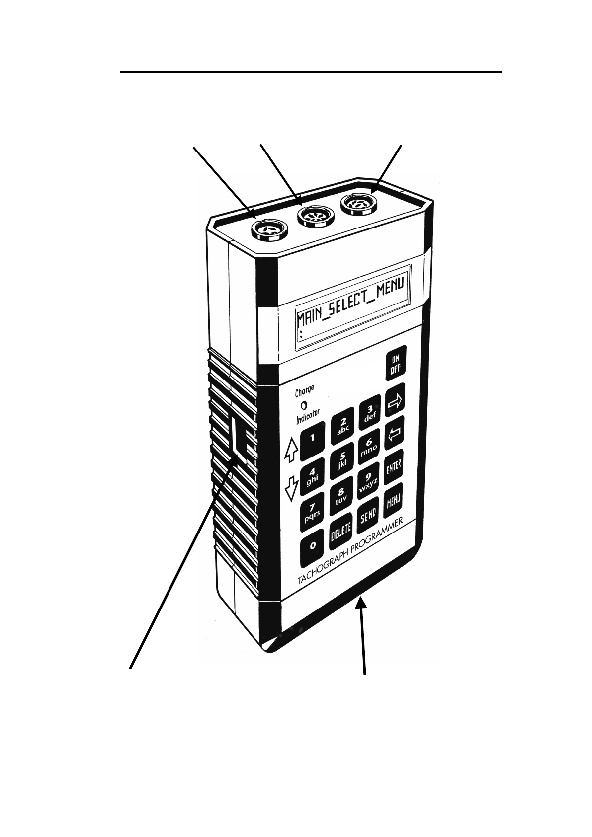
Connectors ............................................................................................................ 6
2.3
Connection Harnesses........................................................................................... 8
2.4
Functions of the Keys ............................................................................................ 8
2.5
Switching On.......................................................................................................... 8
2.6
Diagnostics Menu .................................................................................................. 9
2.6.1
Diagnostics Menu - Function Descriptions .................................................... 9
2.6.2
Diagnostics Menu - Operation of Functions.................................................. 10
2.7
Selection of tachograph type ............................................................................... 12
2.8
Selection of Pulser type (Stoneridge VR8300/1400) ............................................ 12
2.9
Selection of SENDER TYPE (Stoneridge VR2400).............................................. 13
3.
PROGRAMMER FUNCTIONS ....................................................... 14
4.
FUNCTION DESCRIPTIONS......................................................... 17
4.1
Enter PIN Code.................................................................................................... 17
4.2
W-factor (Vehicle Characteristic Coefficient) Determination ................................ 17
4.2.1
Rolling Road (Hartridge or similar) ............................................................... 19
4.2.2
Fixed Distance Method No. 1 ....................................................................... 20
4.2.3
Fixed Distance Method No. 2 ....................................................................... 23
4.3
Bench Test (Connections) ................................................................................... 25
4.4
Distance Test....................................................................................................... 27
4.5
Speed Simulator .................................................................................................. 28
4.6
Revs per minute pulse test .................................................................................. 29
4.7
Clock Test............................................................................................................ 30
4.7.1
Clock Test – Motometer, Stoneridge VR2400/SE5000, Kienzle 1324/DTCO
and Actia Smartach ..................................................................................................... 30
4.7.2
Clock Test – Stoneridge VR8400/8300 Series and Kienzle 1314/1318/1319 31
4.8
Pair/Test Tacho. .................................................................................................. 32
4.9
Tacho Control...................................................................................................... 32

Document No. 6957-193 June 2006 Revision 2.3 ©Copyright Stoneridge Electronics
Ltd Manufacturers of VEEDER-ROOT Tachographs
3
4.10
Identify Tacho – Stoneridge VR2400/SE5000 Series, Kienzle 1324/DTCO and
Actia Smartach................................................................................................................ 33
4.11
Read/Erase DTCs – Stoneridge VR2400/SE5000 Series, Kienzle 1324/DTCO and
Actia Smartach................................................................................................................ 34
4.12
K-Factor Test....................................................................................................... 35
4.13
DIL Calculate ....................................................................................................... 37
4.14
Time / Date.......................................................................................................... 37
5.
PROGRAMMING A TACHOGRAPH.............................................. 38
5.1
Programming Stoneridge VR8400 Series tachographs........................................ 38
5.2
Programming Stoneridge VR2400 Series tachographs........................................ 40
5.3
Programming Kienzle 1324 Series tachographs .................................................. 44
5.4
Programming Kienzle 1319 Series tachographs .................................................. 46
5.5
Programming MotoMeter EGK-100 tachographs ................................................ 49
5.6
Programming SE5000 Series tachographs.......................................................... 51
5.7
Programming DTCO Series tachographs ............................................................ 57
5.8
Programming Smartach Series tachographs ....................................................... 60
5.8
Reading of speed pulses from the front of Kienzle 1314, 1318 and 1319 ............ 63
ANNEX A - TEST HARNESSES FOR USE WITH THE TACHOGRAPH PROGRAMMER .....64
ANNEX B - DETAILS OF BENCH TEST ROUTINES................................................................69
(a) UK Bench Test .....................................................................................................................69
(b) French Bench Test...............................................................................................................71
(c) German Bench Test .............................................................................................................74
(d) Swedish Bench Test.............................................................................................................80
(e) Dutch Bench Test.................................................................................................................82
(f) Belgian Bench Test...................................................................................................................86
(g) Programming of a Custom Bench Test................................................................................90
(h) Digtial Tachograph Bench Test............................................................................................91
ANNEX C - VR2400 SERIES TACHOGRAPH – DIAGNOSTIC TROUBLE CODES (DTC) .....93
ANNEX D - CHARACTER MAP. ................................................................................................94
ANNEX E - LANGUAGE CODES FOR PREFERRED LANGUAGE..........................................94

Document No. 6957-193 June 2006 Revision 2.3 ©Copyright Stoneridge Electronics Ltd
Manufacturers of VEEDER-ROOT Tachographs
4
1. INTRODUCTION
1.1 What does the Tachograph Programmer do?
•Determines the characteristic coefficient (‘W-factor’) of a vehicle using a rolling road or either of
two different fixed-distance methods;
•Carries out bench tests of Tachographs semi-automatically;
•Checks the K-factor setting of Tachographs;
•Calculates the DIL switch settings for any valid K-factor;
•Can be used as a Tachograph speed simulator;
•Determines the appropriate pulses per engine revolution (PPR) setting for a vehicle;
•Allows Tachograph internal parameters to be Read and Checked and Reprogrammed if required
(Note: Stoneridge VR8400/2400/SE5000 Kienzle 1319/1324/DTCO, Motometer EGK100 and Actia
Smartach tachographs only);
•Allows the initiation self-test modes;
•Allows the resetting of the memory to default values;
•Can carry-out a Tachograph Clock Test;
•Can analyse the Diagnostic Trouble Codes (DTC) stored internally in the Stoneridge
VR2400/SE5000, Kienzle 1324/DTCO and Actia Smartach Tachographs (see Annex C for a full
list of DTCs);
•Includes internal diagnostics routines to confirm that the Programmer is functioning correctly.
1.2 With which Tachograph Types can the Programmer be used ?
The Tachograph Programmer can be used with all available types of electronic tachographs, i.e.
Stoneridge VR1400/8300/8400/2400/SE5000, Kienzle 1314/1318/1319/1324/DTCO, MotoMeter
EGK-100 and Actia Smartach.
1.3 How do I use This Manual?
This manual describes, in detail, all the functions performed by the Tachograph Programmer. The
Tachograph Programmer can be used with all electronic tachographs, many of which require
slightly different procedures.
To make it easier to find the information you require, the manual is structured as follows:
Chapter 2: PREPARATION FOR USE
Basic instructions for starting to use the Programmer, including checking and charging the battery,
and how to select the Tachograph type to be programmed.

Document No. 6957-193 June 2006 Revision 2.3 ©Copyright Stoneridge Electronics Ltd
Manufacturers of VEEDER-ROOT Tachographs
5
Chapter 3: MAIN MENU PROGRAMMER FUNCTIONS
Briefly describes the functions performed by the Programmer. A quick-reference Table (Table 1)
lists the functions available for each Tachograph type and the harnesses that are required for each
Programmer function.
Chapter 4: FUNCTION DESCRIPTIONS AND DETAILS OF TEST PROCEDURES
This gives a more detailed description of the different functions available in the Tachograph
Programmer and provides Step-by-step procedures for carrying out the various Tachograph tests
and functions.
Chapter 5: PROGRAMMING A TACHOGRAPH
Once the various Tachograph parameters have been determined (using the Tests described
previously), the values determined must be sent to the Tachograph so that it can be updated with
the correct parameter values.
1.4 What version of Tachograph Programmer Software does this Manual Support ?
This manual covers the Tachograph Programmer functionality for Software version Rev2.03. The
determination of the current Software Version in a Tachograph Programmer is described in
section 2.6 (Diagnostics Menu – ROM Test).
A Tachograph Programmer with an older version of Software can be upgraded to the current
version (i.e., version Rev2.03). For further information on programmer software upgrades, please
A Programmer upgrade is done using a Standard PC running a dedicated installation Program
which is available on a Programmer Upgrade CD.
The PC (Serial Communications Port) is connected to the Programmer (Socket D on Figure 1) via
a Field Download Cable (Part Number: 7780-953).

Document No. 6957-193 June 2006 Revision 2.3 ©Copyright Stoneridge Electronics Ltd
Manufacturers of VEEDER-ROOT Tachographs
6
2. PREPARATION FOR USE
2.1 Power Supply
The Tachograph Programmer is powered from an internal rechargeable nickel metal hydride
battery pack. The voltage of the Battery Pack may be checked at any time by selecting Battery
Detect from the Diagnostics Menu - see section 2.6 (Diagnostics Menu – Battery Detect) for
details.
The 9.6V Battery Pack has a capacity of 600mA/hr. The idle current of the programmer is
approximately 30mA, rising to a maximum of 78mA when in normal use. Standard use of the
communications features results in a current consumption of around 45mA. The OFF state current
consumption is around 35A, which maintains the function of the Programmers internal
temperature compensated real-time clock. Based on these figures, a fully charged battery pack
should give a continuous power on time of approximately 13 hours. Assuming a badly degraded
battery, the programmer should have an expected worst case power-ON time of around 7 hours
before recharge is required.
2.1.1 Battery Charging
The battery is recharged using the AC charger supplied in the Programmer kit (illustrated as
Harness I in ANNEX A - ). When fully discharged, the battery will take approximately 14 hours to
recharge. The unit will then operate for at least 8 hours before requiring recharging. To conserve
battery charge, the unit will switch off automatically after 10 minutes of non-use (except when in a
bench test mode) or if the Voltage drops below 8V - the Critical voltage - below which tests can
become inaccurate.
The Programmer should NOT be continuously connected to the charger after an overnight
charge. This can greatly reduce the Batteries performance, and in extreme cases destroy the
Battery.
2.2 Connectors
The Tachograph Programmer has three connectors on the end of the unit above the display and
two others on the side and on the bottom, as shown on Figure 1 (see below).
A. 6-pin DIN socket for connection of battery charging unit, bench test leads, pulser leads for rolling
road or fixed distance calibration and Stoneridge VR8400 programming leads.
B. 4-pin DIN socket for connection of flexi-switch.
C. 8-pin DIN socket for connection of Stoneridge VR2400/SE5000, Kienzle 1319/ 1324/DTCO,
MotoMeter and Actia Smartach tachographs.
D. RJ11 Socket used for upgrading the Programmer Software version.
E. Smartcard Connector. Smartcards are capable of storing digital information so that the data
stored can be read by suitable electronic devices. The MKII Tachograph Programmer has a
smartcard slot which may be utilised in the future for a variety of uses including security.

Document No. 6957-193 June 2006 Revision 2.3 ©Copyright Stoneridge Electronics Ltd
Manufacturers of VEEDER-ROOT Tachographs
7
FIGURE 1: MKII TACHOGRAPH PROGRAMMER OUTLINE
Socket B Socket C Socket A
Socket D Socket E

Document No. 6957-193 June 2006 Revision 2.3 ©Copyright Stoneridge Electronics Ltd
Manufacturers of VEEDER-ROOT Tachographs
8
2.3 Connection Harnesses
A range of different connection harnesses is supplied in the Programmer kit to allow many
different connections to tachograph systems according to the functions required. These are
illustrated and described in Annex A, and are referred to as appropriate throughout this manual.
2.4 Functions of the Keys
MENU - Press to return to the MAIN MENU
ENTER - Either selects a setting to be changed or terminates an entry.
- Cycles through the options available for a particular setting. Press either of
these keys as appropriate to move to the required function and then press
ENTER to select.
SEND - Sends parameter information to the attached tachograph.
DELETE - Allows deletion of the entered value.
0 ... 9 - Numeric keys for entry of numeric values. They also have the secondary
function as shortcut keys (see below) and the tertiary function of inputting
letters.
- The 1 and 4 keys have an additional function and are used to alter the speed
in a speed test.
ON/OFF - Used for turning the instrument on and off. Note that if the unit is left for 10
minutes without any keys being pressed then the unit will turn off
automatically (except in bench test mode).
Shortcut keys- to facilitate faster and easier use of the Programmer, the number keys also
have shortcut key functions (the shortcut keys are only active if the Tachograph
type selected supports the function). The shortcuts are as follows:
1- Rolling Road test.
2- Fixed Distance #1 test.
3- Fixed Distance #2 test.
4- Clock test.
5- R.P.M. Pulse test.
6- K-Factor test.
7- Read All Data.
8- Modify Data.
9- Send All Data.
2.5 Switching On
To switch ON the Tachograph Programmer, press the ON/OFF button on the keyboard. The unit
will first display a copyright message and the software version and then, after an audible beep, will
display the MAIN MENU. From this menu the required functions may be selected.
If the ENTER key is held down while switching ON, the Programmer will request a Pass code –
type “8642” and press “ENTER” – the Programmer will then enter the Diagnostics Menu. Please
note that the use of the Pass code is only to prevent unwanted entry to the Diagnostics Menu. The
Diagnostics functions are described in Section 2.6.

Document No. 6957-193 June 2006 Revision 2.3 ©Copyright Stoneridge Electronics Ltd
Manufacturers of VEEDER-ROOT Tachographs
9
2.6 Diagnostics Menu
Within the Tachograph Programmer there are a number of additional functions provided which
carry out various self-test functions and which allow setting of various default values.
To gain access to the internal utilities, first ensure that the Tachograph Programmer is turned off.
Press and hold the ENTER key and then turn on the unit by pressing the ON key. As the unit
turns on it will emit a beep as usual, but in this case will request a Pass code – type “8642” and
press “ENTER” – the Programmer will then enter the DIAGNOSTICS MENU.
2.6.1 Diagnostics Menu - Function Descriptions
Language Select - The MKII Tachograph Programmer may be operated in a number of
different languages. The available languages are dependant on the
Tachograph Programmer type.
Set Time and Date - This is used to set the time (24 hour clock) and date (ddMMyyyy format)
used by the Programmer.
Fixed Distance Length - This allows the Length of the Fixed Distance Track (used in Programmer
Fixed-Distance Tests) to be altered between 20 and 1000m (previously
this was fixed at 20m permanently).
Hardware Test - This function is used in conjunction with an external test jig for
conformance testing. It is for use by SE personnel only.
Keyboard Test - This enables the user to check that the keyboard is fully functional by
pressing each key in turn.
Display Test - This causes the unit to display a visual routine so that the user can check
that the display is functioning correctly.
ROM Test - This function can be used to check the Programmer’s internal read-only
memory (ROM) and display the result.
Battery Detect - This is used to check the Voltage of the Programmer’s internal battery
pack. If within tolerance, message “Battery OK!” should be displayed. If
not then the battery needs recharging.
Frequency Test - Used during conformance testing to calibrate the accuracy of the clock
within the Tachograph Programmer. This function is for use by SE
personnel only.
Set calib no. - This enables a user to enter a default identification string for a particular
tachograph fitting station. Generally this is the identification issued by the
approvals authority.
Bench test type - This allows the selection of the appropriate bench test for any given
country. Standard bench tests are pre-programmed for several countries;
selecting the Custom bench test option allows a user to define a different
test sequence. See Annex B for details of the Bench Tests available and
instructions for programming a custom bench test.

Document No. 6957-193 June 2006 Revision 2.3 ©Copyright Stoneridge Electronics Ltd
Manufacturers of VEEDER-ROOT Tachographs
10
2.6.2 Diagnostics Menu - Operation of Functions
With the Programmer OFF, press and hold the
ENTER key and switch the device ON.
To prevent unintentional use of the
Diagnostic functions, a pass code will be
requested. Type in 8642, and press
ENTER. By pressing the ←
←←
←or →
→→
→keys the
required function may then be displayed.
Enter PIN
:8642
Language Select - Press ENTER and the
current language and the characters ←→will
be displayed (on the right of display).
Press the required key (←or →) until the
required language is shown and then press
ENTER again to make the selection
permanent.
DIAGNOSTICS MENU
:Language Select
The language selected will then be used for all
the operating menus until a different language
is selected.
Press MENU once to return to the
DIAGNOSTICS MENU.
SELECT LANGUAGE
:English ←
←←
←→
→→
→
Set time & date - Press ENTER and type in
the time in the format shown on the screen.
Press ENTER after setting the time to set the
date in the format shown on the screen.
When the time and date have been set, press
ENTER to confirm the settings.
Note : The time entered should be UTC time.
DIAGNOSTICS MENU
:Set time & date
Time: HHmm
:09:45
Date: ddMMyyyy
:01/07/2003
Fixed Dist leng – Press ENTER to display the
Fixed Distance Length.
Press ENTER to change the distance (Note:
Range is 20 to 1000m). Enter the distance
required and press the ENTER key to accept.
Press MENU to return to the Diagnostic Menu.
DIAGNOSTICS MENU
:Fixed Dist leng
Enter distance
:20 m
Hardware Test – This test is to be applied by
the manufacturer only.
DIAGNOSTICS MENU
:Hardware Test
Keyboard Test - Press ENTER and then DIAGNOSTICS MENU

Document No. 6957-193 June 2006 Revision 2.3 ©Copyright Stoneridge Electronics Ltd
Manufacturers of VEEDER-ROOT Tachographs
11
press the correct key when prompted. When
the test is successfully completed the
message: Keyboard OK! will appear briefly on
the screen.
:Keyboard Test
Display Test - Press ENTER to start the test
procedure.
The default contrast is 25% but this may be
changed using keys 1 or 4.
Press ENTER and the test runs automatically.
DIAGNOSTICS MENU
:Display Test
Adjust contrast
:25%
ROM Test - Press ENTER to start the test
procedure.
The Checksum will appear after a brief
interval.
Press the MENU key once to return to the
Diagnostics Menu.
Note that the actual checksum value will depend on
the version of software in the Programmer.
DIAGNOSTICS MENU
:ROM Test
(c)2006 Rev 2.03
:Checksum = XXXX
Battery Detect - Press ENTER to start the
test procedure.
The battery voltage will appear after a brief
interval.
Press the MENU key once to return to the
Diagnostics Menu.
DIAGNOSTICS MENU
:Battery Detect
Battery OK!
:11.239V
Frequency Test – This test is to be applied by
the manufacturer only. DIAGNOSTICS MENU
:Frequency Test
Set calib no. - Press ENTER to view the
current calibration number.
Press ENTER a second time to change the
calibration number if necessary.
Once the number has been changed, press
ENTER a third time to confirm the new values.
Press the MENU key to return to the
DIAGNOSTICS MENU.
DIAGNOSTICS MENU
:Set calib no.
Set calib no.
SE 1234

Document No. 6957-193 June 2006 Revision 2.3 ©Copyright Stoneridge Electronics Ltd
Manufacturers of VEEDER-ROOT Tachographs
12
Benchtest type - Press ENTER to display the
current Benchtest type.
Use the ←or →keys to select UK, French,
German, Swedish, Dutch, Belgium or to
Custom the bench test procedure.
Press ENTER to select the required type.
DIAGNOSTICS MENU
:Benchtest type
Benchtest type
:UK ←
←←
←→
→→
→
2.7 Selection of tachograph type
Before using the Programmer, the model of tachograph
being calibrated must be selected from the Main Menu.
When the Programmer is switched on the first item displayed
on the MAIN MENU is TACHO SELECT. From elsewhere in
the MAIN MENU press the ←or →keys until TACHO
SELECT is displayed.
Press ENTER and the TACHO TYPE menu will be displayed.
Press ENTER again and then use the ←or →keys to select
the appropriate tachograph type (Stoneridge
VR2400/8400/8300/1400/SE5000 series, Kienzle
1324/1319/1318/ 1314/DTCO, Motometer EGK-100 and
Actia Smartach). Press ENTER to make the selection and then MENU to return to the MAIN
MENU.
2.8 Selection of Pulser type (Stoneridge VR8300/1400)
For Stoneridge VR8300 or VR1400 series tachographs, the
pulser type to be used must also be selected. This is to
ensure that any calibration factor determined is correct.
With the Programmer at the MAIN MENU and displaying
PULSER SELECT, press ENTER and PULSER TYPE will be
displayed. Use the ←or →keys to select the appropriate
pulser type. Press ENTER to make the selection and then
MENU to return to the MAIN MENU.
Note: The 2 pulse/rev option should only be selected when the tachograph is fitted with a
Stoneridge Veeder-Root 2-pulse sender. The 8 pulse/rev option must be selected for all other
pulsers regardless of the actual number of pulses per rev from the sender.
VR2400 MAIN MENU
:TACHO SELECT
TACHO TYPE
:2400 Series
VR1400 MAIN MENU
:PULSER SELECT
PULSER TYPE
:8 Pulses/Rev ←
←←
←→
→→
→

Document No. 6957-193 June 2006 Revision 2.3 ©Copyright Stoneridge Electronics Ltd
Manufacturers of VEEDER-ROOT Tachographs
13
2.9 Selection of SENDER TYPE (Stoneridge VR2400)
For Stoneridge VR2400 series tachographs, the sender type
may be selected.
With the Programmer at the VR2400 MAIN MENU and displaying PULSER SELECT, connect a
Cable U between the Programmers’ Socket ‘C’ and the 2400 Tachograph and then press ENTER.
Use the ←or →keys to scroll through the options until the preferred sender type is displayed.
Press ENTER and again to confirm the selection. The four choices available for sender Type are:
Encrypted, 4-Wire, 3-Wire and Magnetic.
Please note that for all other Tachograph types no sender type is selectable.
VR2400 MAIN MENU
:PULSER SELECT
SENDER TYPE
: Encrypted ←
←←
←→
→→
→

Document No. 6957-193 June 2006 Revision 2.3 ©Copyright Stoneridge Electronics Ltd
Manufacturers of VEEDER-ROOT Tachographs
14
3. PROGRAMMER FUNCTIONS
This Chapter briefly describes all the MKII Programmer functions and lists the required harnesses in
Table 1. A full description of each function is included in Chapter 4.
•Tacho Select - this function allows the operator to specify the tachograph type that is to be
calibrated or tested by the Programmer (see section 2.7 for more details).
•Pulser Select (Stoneridge VR8300/1400 and Kienzle 1314) – this function allows the operator
to specify the pulser type (or sender type for VR2400) that is being used with the current
tachograph (see sections 2.8 and 2.9 for more details).
•Rolling Road Test (all) - this function finds the “W” factor of the vehicle using the Hartridge (or
similar) Rolling Road (see section 4.1.1 for more details).
•Fixed Distance #1 Test (all) - this function finds the “W” factor of the vehicle using the
Physical method 20m track (see section 4.1.2 for more details).
•Fixed Distance #2 Test (all) - this function finds the “W” factor of the vehicle using the
Physical method 20m track with Flexi-Switch (see section 4.1.3 for more details).
•Bench Test (all) - this semi-automatic function assists the fitter to bench test the tachograph
using a series of commands displayed on the screen (see section 4.2 for details of Bench Test
connections and Annex B for full details of all Bench Test Routines).
•Speed Simulator Test - this function injects speed pulses into the tachograph for checking of
tachograph speed pointer, overspeed warning, or stylus positions on chart (see section 4.3 for
more details).
•RPM Pulse Test (Stoneridge VR2400/8400/8300, Kienzle1318, Motometer EGK100, 4-stylus
tachographs only) - this function is used to find the “Pulse Per Engine Rev” from the “W”
terminal on the alternator or a revs sender (see section 4.4 for more details).
•Clock Test - this function checks the accuracy of the tachograph clock. The function is
automatic for Motometer EGK100 tachograph, Stoneridge VR2400/SE5000, Kienzle
1324/DTCO and Actia Smartach but uses an optional external clock-tester for other
tachographs (see section 4.5 for more details).
•Tacho Control (Stoneridge VR8400/2400 and Kienzle 1324) - this function is used to put the
tachograph into either the “Self Test” or the “Extended Test” mode, to Reset the tachograph
memory to the “Default state” or to pair a tachograph with a sender (2400/1324 only) (see
section 4.8 for more details).
•Identify Tacho (Stoneridge VR2400/SE5000, Kienzle 1324/DTCO and Actia Smartach) – this
function interrogates the tachograph via the K-line and determines the System supplier,
Manufacture date, Serial number, Hardware version, Software number, Software version and
System name (see section 4.9 for more details).
•Read/Erase DTCs (Stoneridge VR2400/SE5000, Kienzle 1324/DTCO and Actia Smartach) -
enables the Diagnostic Trouble Codes in the tachograph to be displayed on the Programmer
and then erased if required (see section 4.10 for more details).
•Read all data/ Modify data/ Send all data (Stoneridge VR2400/SE5000, Kienzle
1319/1324/DTCO, EGK100 and Actia Smartach) - these functions interrogate the tachograph
via the K-line to allow the fitter to change the various settings on the tacho and program all the
data set-up in the Programmer in a single operation (see Chapter 5 for more details).

Document No. 6957-193 June 2006 Revision 2.3 ©Copyright Stoneridge Electronics Ltd
Manufacturers of VEEDER-ROOT Tachographs
15
•Program Tacho (Stoneridge VR8400) - this function can be used to select various settings
such as “Ignition Recording On” and “Overspeed Setting” (see section 5.1 for more details)..
•K-factor Test (Stoneridge VR8400 and Kienzle 1319, 1318, 1314) - this function measures the
“K” factor currently set on the tachographs (see section 4.11 for more details).
•DIL calculate (Stoneridge VR8400/8300/1400, Kienzle1318) - this function eliminates the need
to look up calibration tables (see section 4.12 for more details).
•Time/Date (Stoneridge SE5000, Kienzle DTCO, Actia Smartach) – this function allows the
time/date, and time offset in the tachograph to be read and modified.
•Pair/Test (Stoneride SE5000, Kienzle DTCO) – this function can be used to pair the sender,
and allow a number of tests to be carried out on the tachograph.
Table 1: Available functions and required harnesses
Tachograph
Function
VR240
0
VR840
0 VR830
0 VR140
0 K1324 K1319 K1318 K1314 Moto-
Meter
EGK10
0
SE500
0 DTCO Smar-
tach
Rolling
Road U or D G+J or
D G+J or
D K W or D G+O+J G+J or
D G+J or
L N Z or D Z or D Z or D
Fixed Dist
#1 U or D G+J or
D G+J or
D K W or D G+O+J G+J or
D G+J or
L N Z or D Z or D Z or D
Fixed Dist
#2 U or D G+J or
D G+J or
D K W or D G+O+J G+J or
D G+J or
L N Z or D Z or D Z or D
Bench Test C G+S+J
or C C K C or O G+O+J
or C G+S+J
or C G+T+J
or L C+M
or N Z Z Z
Speed
Simulator U or C G+S+J
or C C K W or C G+O+J
or C G+S+J
or C G+T+J
or L C+M
or N Z Z Z
RPM Pulse
Test E E E - W - E - N - - -
Clock Test U Clock
Tester Clock
Tester - W Clock
Tester Clock
Tester Clock
Tester N Z Z Z
Tacho
Control U G+J - - W or C - - - N - - -
Identify
Tacho U - - - W - - - - Z Z Z
Read/Erase
DTCs U - - - W - - - - Z Z Z
Table 1: Available functions and required harnesses (continued)
Tachograp
h
Function
VR240
0
VR840
0 VR830
0 VR140
0 K1324 K1319 K1318 K1314 Moto-
Meter
EGK1
00
SE500
0 DTCO Smar-
tach

Document No. 6957-193 June 2006 Revision 2.3 ©Copyright Stoneridge Electronics Ltd
Manufacturers of VEEDER-ROOT Tachographs
16
Send All
Data U G+J - - W P - - N Z Z Z
Modify
Data U - - - W P - - N Z Z Z
Read All
Data U - - - W P - - N Z
Z Z
Program
Tacho - G+J - - - - - - - -
- -
K-Factor
Test - G+J - - - G+O+
J G+J G+J - -
- -
Pair / Test - - - - - - - - - Z
Z -
Time / Date - - - - - - - - - Z
Z Z
Enter PIN - - - - - - - - - Z
- -
Notes:
(1) Fixed Distance #2 also requires the Flexi Switch.
(2) DIL Calculate and Tacho Select and Pulser Select do not require any connections.

Document No. 6957-193 June 2006 Revision 2.3 ©Copyright Stoneridge Electronics Ltd
Manufacturers of VEEDER-ROOT Tachographs
17
4. FUNCTION DESCRIPTIONS
This chapter describes the application of the Tests available in the MKII Tachograph Programmer,
gives details of the connections required for each and provides a step-by-step instruction guide for
each function for the inexperienced user.
4.1 Enter PIN Code.
In order to read or inject pulses or to write data via the front programming connector of a digital
tachograph, the tachograph must be put into calibration mode. Calibration mode consists of a
valid workshop card being inserted into the tachograph, and a PIN code entered.
In the case of the SE5000 the PIN code can be entered either through the tachographs keypad, or
via the programmer. A PIN code function is available through the Main Menu, but the programmer
may also prompt for a PIN code if a function is attempted while the tachograph is not in calibration
mode.
Entering a PIN through the programmer operates in a similar manner to SMS messaging.
Continually pressing a key will cycle through a list of characters under that key. Pressing a new
key or waiting for approx 5 seconds, will move to the next character. Pressing Enter will ask the
tachograph to authenticate the PIN. If too many characters are entered, use the arrow and delete
keys to correct.
The list of characters under each key is detailed in Annex D
In the case of the DTCO the PIN code can only be entered through the tachograph keypad.
Insert the workshop card into the tachograph, and insert the front connector from the programmer
into the Tachograph.
From the MAIN MENU select ENTER PIN
using the ←and →keys. Press ENTER.
SE5000 MAIN MENU
:ENTER PIN
The programmer should request the code to
be entered. Enter the correct Code for the
workshop card and Press Return
Enter PIN
:
4.2 W-factor (Vehicle Characteristic Coefficient) Determination
The MKII Tachograph Programmer can use three different methods of determining the W-factor
for a vehicle, namely Rolling Road, Fixed Distance #1 and Fixed Distance #2. In each case the
W-factor (revs/km for a 2-pulse sender or pulses/km for other senders) is determined and
displayed. Where appropriate the correct setting of the tachograph DIL switches is indicated.
The choice of the method to be used will depend on the other facilities available. However, the
connections between Programmer and tachograph or sender are the same for all three of the
calibration methods used:

Document No. 6957-193 June 2006 Revision 2.3 ©Copyright Stoneridge Electronics Ltd
Manufacturers of VEEDER-ROOT Tachographs
18
Table 2: W-factor Test connections
Tachograph Harness Connection
Stoneridge VR2400
Series U or
D Connect to front of tachograph or directly to the
vehicle sender.
Stoneridge VR8400/
8300 Series, G +
clip J
or D only
Jack plug of harness G to socket inside front of
Tachograph
DIN plug of harness G to Programmer socket A;
Use Crocodile clip J to make required ground
connection to a suitable point on the vehicle.
Stoneridge VR1400
Series K DIN plug of harness K to Programmer socket A;
connect appropriate black plug into socket on
back of tachograph;
connect other black plug directly to vehicle
sender.
Kienzle 1314 G+J or L only As 8400 or
DIN plug of harness L to Programmer socket A;
Connect appropriate white plug into socket on
back of tachograph;
Connect other white plug directly to vehicle
sender.
Kienzle 1318 C or G+J Jack plug of harness G to socket inside
tachograph
DIN plug of harness G to Programmer socket A;
Use Crocodile clip J to make required ground
connection to a suitable point on the vehicle.
Or DIN plug of harness C to socket A on
Programmer and other end to socket B of
tachograph.

Document No. 6957-193 June 2006 Revision 2.3 ©Copyright Stoneridge Electronics Ltd
Manufacturers of VEEDER-ROOT Tachographs
19
Kienzle 1319 C or G+O+J Jack plug of harness G to socket on harness O
and 8 way connector of O to socket inside
tachograph.
DIN plug of harness G to Programmer socket A;
Use Crocodile clip J to make required ground
connection to a suitable point on the vehicle.
Or DIN plug of harness C to socket A on
Programmer and other end to socket B of
tachograph.
Kienzle1324 W DIN plug to Programmer socket C. Other end to
D-shaped socket on front of tachograph.
MotoMeter EGK-100 N One DIN plug of harness N to Programmer
socket A;
Other DIN plug to MotoMeter programming
socket.
SE5000/DTCO/
Smartach Z DIN plug to Programmer socket C. Other end to
D-shaped socket on front of tachograph.
All tachographs (Fixed
Distance #2 test) Flexi-switch Connect to Programmer socket B, and mount
flexi-switch on vehicle chassis.
Where a suitable connection is not available on the front of the tachograph to read pulses from the
sender, it is necessary to make a connection direct to the sender, using Harnesses D(Stoneridge
VR8300/8400/2400/SE5000 series, Kienzle 1319/1324/DTCO Series and Actia Smartach), K
(Stoneridge VR1400 series) and L(Kienzle 1314). The tachograph is bypassed completely when
using these harnesses, and a separate ground connection is not required.
4.2.1 Rolling Road (Hartridge or similar)
This method uses the Tachograph Programmer in conjunction with a rolling road. The vehicle to
be calibrated is positioned with its driving wheels on the rollers of the rolling road and is then
driven at a constant speed of 50km/h. The Tachograph Programmer will then determine the W-
factor.

Document No. 6957-193 June 2006 Revision 2.3 ©Copyright Stoneridge Electronics Ltd
Manufacturers of VEEDER-ROOT Tachographs
20
Procedure
Select ROLLING ROAD from the Main Menu, and follow the instructions as displayed below;
From the MAIN MENU select ROLLING
ROAD (shortcut key 1)using the ←and →
keys. Press ENTER.
VR2400 MAIN MENU
:ROLLING ROAD
Increase the speed of the vehicle as indicated
by the rolling road equipment until it is steady
at 50km/h.
Hold at 50km/h
ENTER to Start
Press ENTER and the Programmer will start
counting pulses. The pulses will be audible as
low-pitched clicks.
Hold at 50 km/h
Reading pulses
After about 15 seconds it will emit an audible
beep and the measured W-factor will be
displayed. If appropriate for the selected
tachograph type the measured K-factor and
the required DIL switch setting will be
displayed. For Stoneridge VR2400/SE5000,
Kienzle 1319/DTCO, MotoMeter EGK-100 and
Actia Smartach tachographs the required W-
factor will be retained in the Programmer (until
the Programmer is turned off) ready for later
programming of the tachograph, as described
in Chapter 5.
W=8000 K=8000
DIL=_23_____9_
Note: In the case of the message ERROR!
CHECK CONNECTIONS being displayed,
ensure that the ground connection is made
correctly. Otherwise check the other
connections.
ERROR! CHECK
CONNECTIONS
4.2.2 Fixed Distance Method No. 1
This method typically uses the 20m measured distance often available at tachograph fitting
stations, but it is possible to set to any distance from 20 to 1000m as required. The Fixed
Distance Length can be adjusted via the Diagnostics Menu (see Section 2.6).
Care must be taken to ensure that the Fixed Distance Length set and the actual track length are
the same, otherwise the W-Factor determined will be incorrect.
The vehicle is driven along the measured track and measurements made at either end of the track
are fed into the Programmer, from which the W-factor is determined.
Table of contents