_
1 2 3 4 5 6
1 2 3 1 2 3 4 5 6 7 8 9 10 11 12 13 14
1 2 3 4 5 6 7 1234
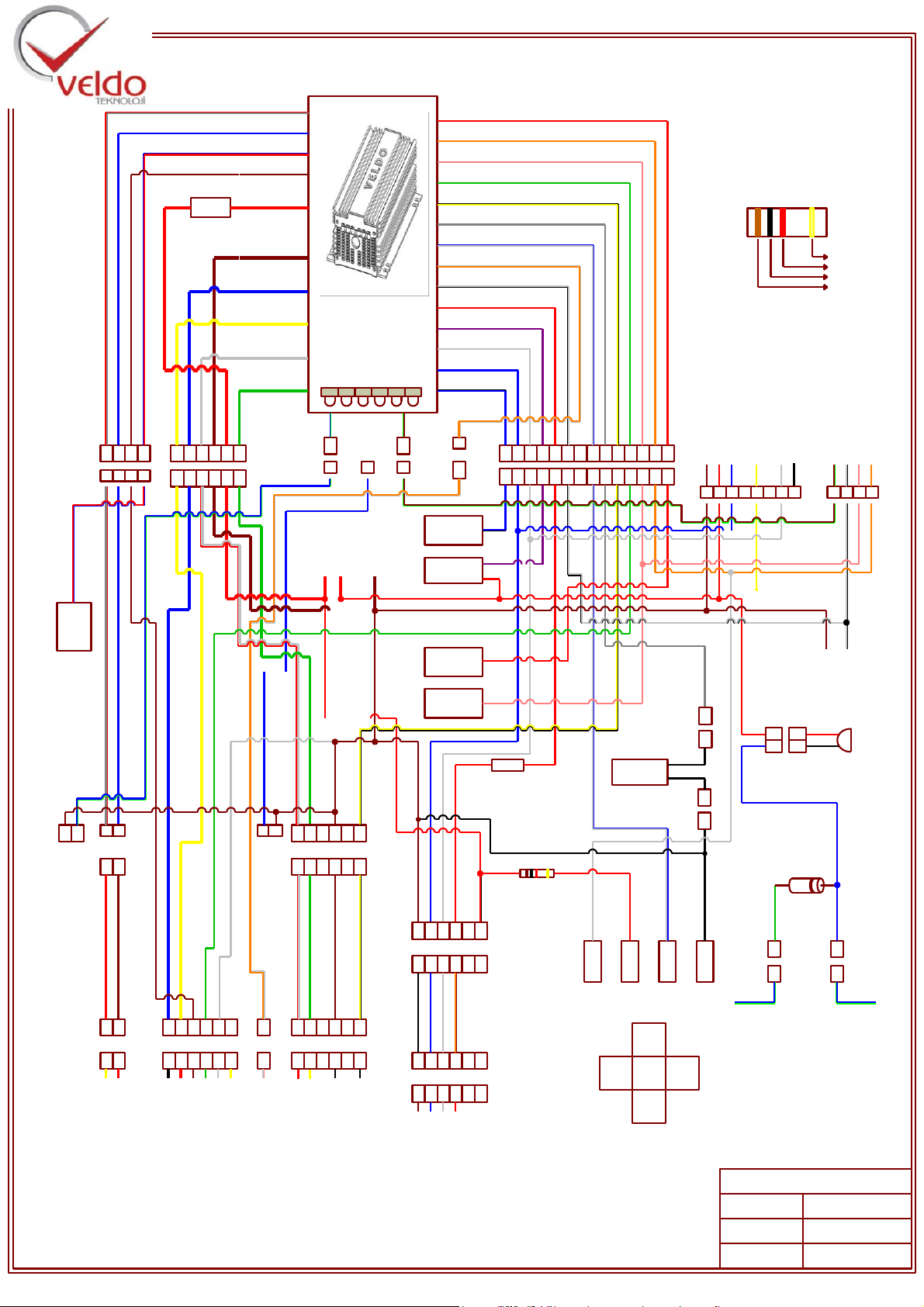
RF Output
Centre Door
Controller
Signal
Grand - Brown
12V - Red
Doorhand Button - Blue
Antenna - Yellow
Security Wick -White
Learn End - Black
Contact GND - Brown Green
Handbrake –White Black
Speed Km - Pink
Step Communication - Orange
1 2 1 2 3 4 5 6
1 2 3 4 5 6
Spped
(Km Connection)
Gray
Black
White
-+
COM
ON
NC
ON
+-
COM
Front Panel
Button
Connections
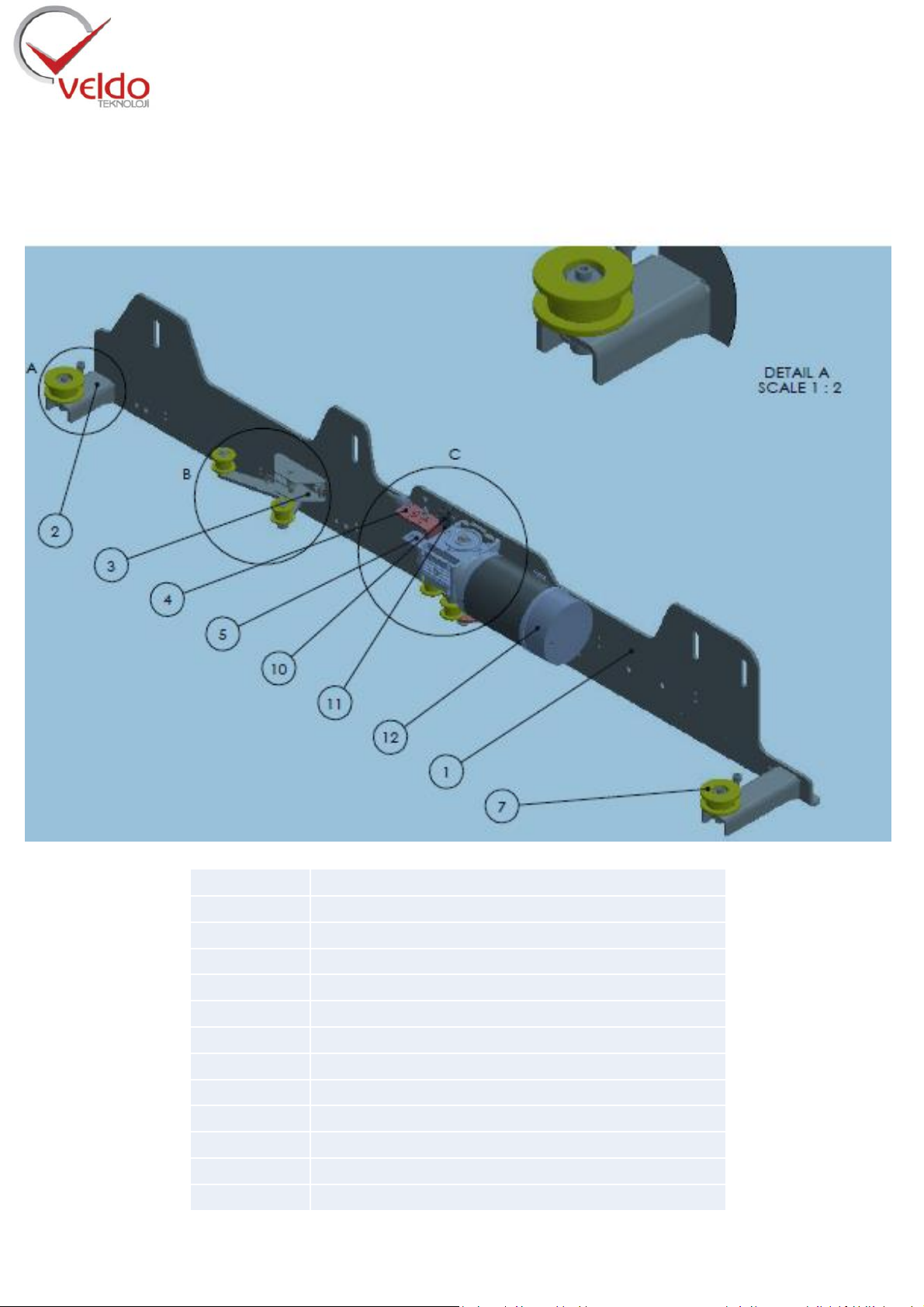
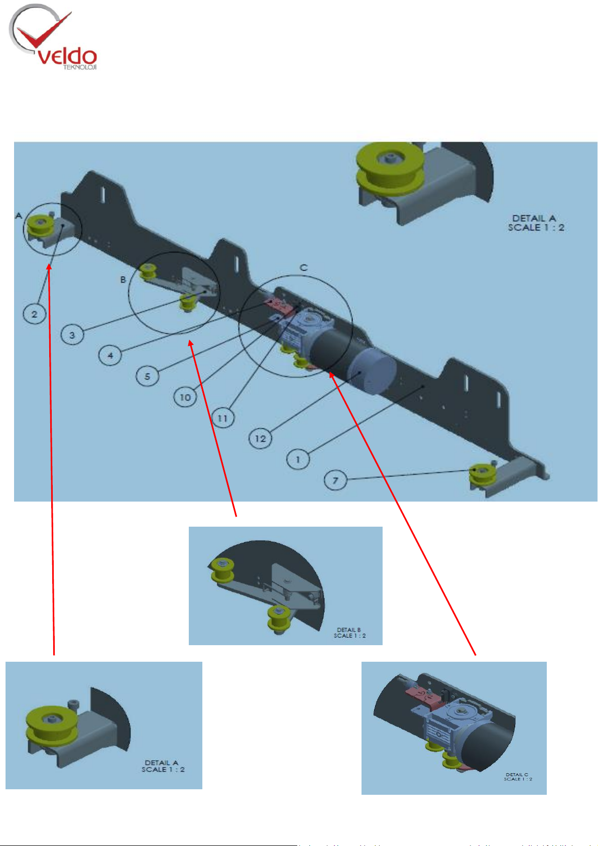
Lock Puller Motor Socket
Down Main System Motor Socket
Encoder B Signal - Yellow
Encoder GND - White Chassis
Encoder A Signal –Green
+12V Encoder –Brown
Main Motor 1 - Red
Main Motor 2 –Black
Lock Puller Motor 1 - Yellow
Lock Puller Motor 2 -Red
Reedröle_GND - Black
KCK_Reedrelay -Black
GND - Brown
Door Hand -Blue
Cable Puller - Red
Security -White
1
Handbrake
4
1 2
1 2
1 2 3 4 5 6
1 2 3 4 5 6
+12V - Red Blacj
1 2 3 4 5 6
1 2 3 4 5 6
1 2 3 4 5 6 7 8 9 10 11 12 13 14
Handbrake - White Black
Step Communication - Orange
Spped / Kilometer Output - Pink
Encoder A Signal - Green
KCK –Yellow Black
Door Stop Reedrelay - Gray
Front Panel Button - White Blue
Switch - Red
Cable Puller Motor +12V - Red
Centre Door Control Signal- Purple
Safety Fuse - White
Doorhand-Blıe
(Blue Black)
1 2 3 4 5 6
Chassis - Brown
Main Motor 2 - Blue
Main Motor 1 - Yellow
lock Puller. Motor 2
White
Lock Puller. Motor 1
Green
+12V Encoder - Brown
Safty
Fuse
30Amper
+12V -Red
1
1 2 3 4
8
FUSE
++
VELDO TEKNOLOJİ
FACILITYNAME
REVISION
DROWNBY
MAIN SYSTEM
FACILITY
SKK260E - V15
MEHMETDURAN
Step Communication
12V Buzzer
Red
Black
Black
1K /2W
Panel Button Resistor
Gold /Silver
Red
Black
Brown
Panel
ButtonResistor
Switch_GND
Brown Green
Contact
Signal
1N5408
11
11
1 2
1 2
Red
Blue
Door SideWheel Side
Right front door emergancy
buzzer connection
1 - Blue green cable cut off
which is in Right front door
cable group
2 - Diode buzzer connected like the
picture
KCK -Lock Reedrelay
Handbrake
Securşty Wick
Doorhand
Panel Button
Reedelay
OnePlatinous
Reedrelay
Door Inside Opkon
Socket
1 2 3 4 5 6
1 2 3 4 5 6
Door Inside Facility
Socket
1 2 3 4 5 6
1 2 3 4 5 6
Door Hand -Blue
GND - Brown
Security-White
Cable Puller - Red
Black- Chassis
Blue
Brown - Orange
White
Clutch New Door System Facilities
Opkon Cable
Red Blue Right Front
Door
Centre Lock
Close Signal
EEmergan exit buzzer switchi 1 - Grey Red
Emergan exit buzzer switchi 2 - Blue
Right Front Door Centrel lock Close Signal –Red Blue
Right Front Door
Center lock Open
Signal
Central door back lock signal –Orange White
Right Front Door
Centre Lock
OpenSignal
1
Centre Door Back Lock Signal - Pink White
Sağ front door cable group
connect to blue red cable
1
1
1
1
Coupler Space Control Unit
1
1
1
1 2
Fuse
5 Amper Thermic
1 2
11
External
External -
Blue
Kav_SW
Kav_SW - Blue Green
1
1 2
Grasp Motor
Grasp Motor
Grasp Motor Socket
Grasp Motor Insert Connection