VentilClima Air Hygienic Series User manual

INSTALLATION, USE,
MAINTENANCE MANUAL
AIR HYGIENIC
CENTRIFUGAL FAN COIL UNIT
2018-1

INSTALLATION, USE,
MAINTENANCE MANUAL Vers. 2018-0 centrifugal fan coil unit
2
!
1) THE FILTER MUST BE KEPT CLEAN
2) CLEAN THE FILTER MAXIMUM FOR TWO TIMES
AND THEN REPLACE IT.
FURTHERMORE FILTER MUST BE REPLACED WITH
A NEW ONE AT LEAST EVERY 12 MONTHS
ATTENTION!

INSTALLATION, USE,
MAINTENANCE MANUAL
Vers. 2018-0
centrifugal fan coil unit
3
INDEX
INTRODUCTION 4
RECOMMENDATIONS 4
TRANSPORTATION, RECEIVING, HANDLING 4
SAFETY RULES 4
GENERAL DIMENSIONS 5
DIMENSIONAL CHARACTERISTICS 5
MAIN COMPONENTS 6
RECOMMENDATIONS FOR INSTALLATION 6
FAN COIL INSTALLATION 6
WATER CONNECTIONS 7
Connection to the water mains 7
Condensate water drainage 8
WORK LIMITS 8
ELECTRICAL CONNECTION 8
CONNECTIONS TO THE TERMINAL BOARD 8
Without control panel 8
With control panel 8
CHANGING THE MOTOR SPEED OF ROTATION 8
TESTING THE FANCOIL 8
TURNING THE COIL 8
CLEANING AND MAINTENANCE 9
WHAT TO DO IF... 12
DISMALTING THE APPLIANCE 12

INSTALLATION, USE,
MAINTENANCE MANUAL Vers. 2018-0 centrifugal fan coil unit
4
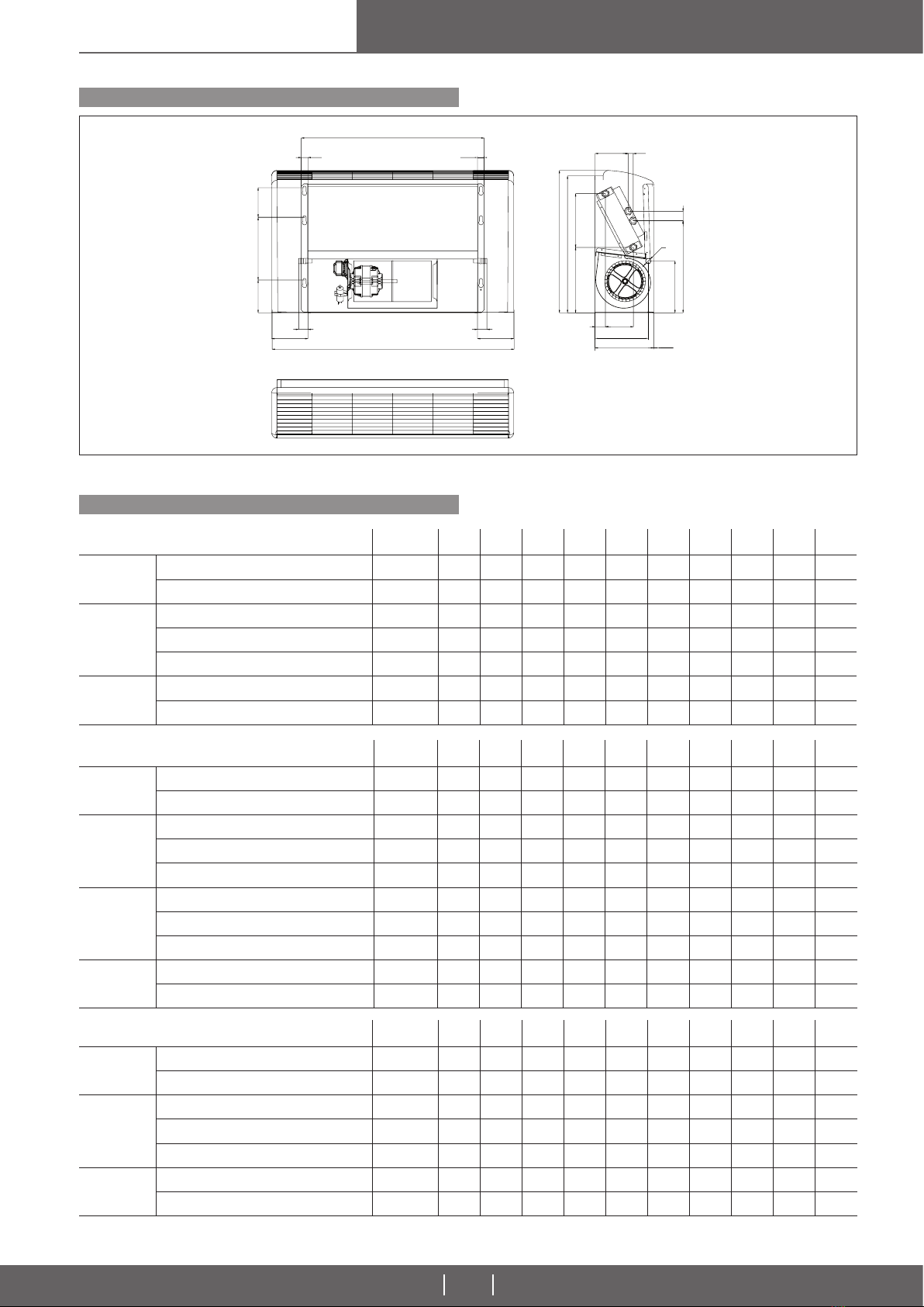
INTRODUCTION TRASPORTATION, RECEIVING, HANDLING
SAFETY RULES
RECOMMENDATIONS
This installation, operation and maintenance booklet should always accompany
the fancoil ready consultation by the installer or user if necessary. The appliance
should be installed in compliance with regulations in force in each country and
according to the manufacturer’s or qualied installer’ instruction. The manufac-
turer cannot be held liable for any damage to property or injury to persons and
animals caused by incorrect installation of the appliance. Only qualied persons
should install the appliance and connect it to the mains electricity supply. Before
carrying out any work on the appliance, ensure that it disconnected from the
electricity supply. Read this instruction booklet before installing the appliance.
The appliance is dispatched enclosed in special protective packaging, which
should be kept intact until the appliance is positioned in the nal place of in-
stallation.
The appliance should be handled with extreme care, always keeping it in its
original packaging.
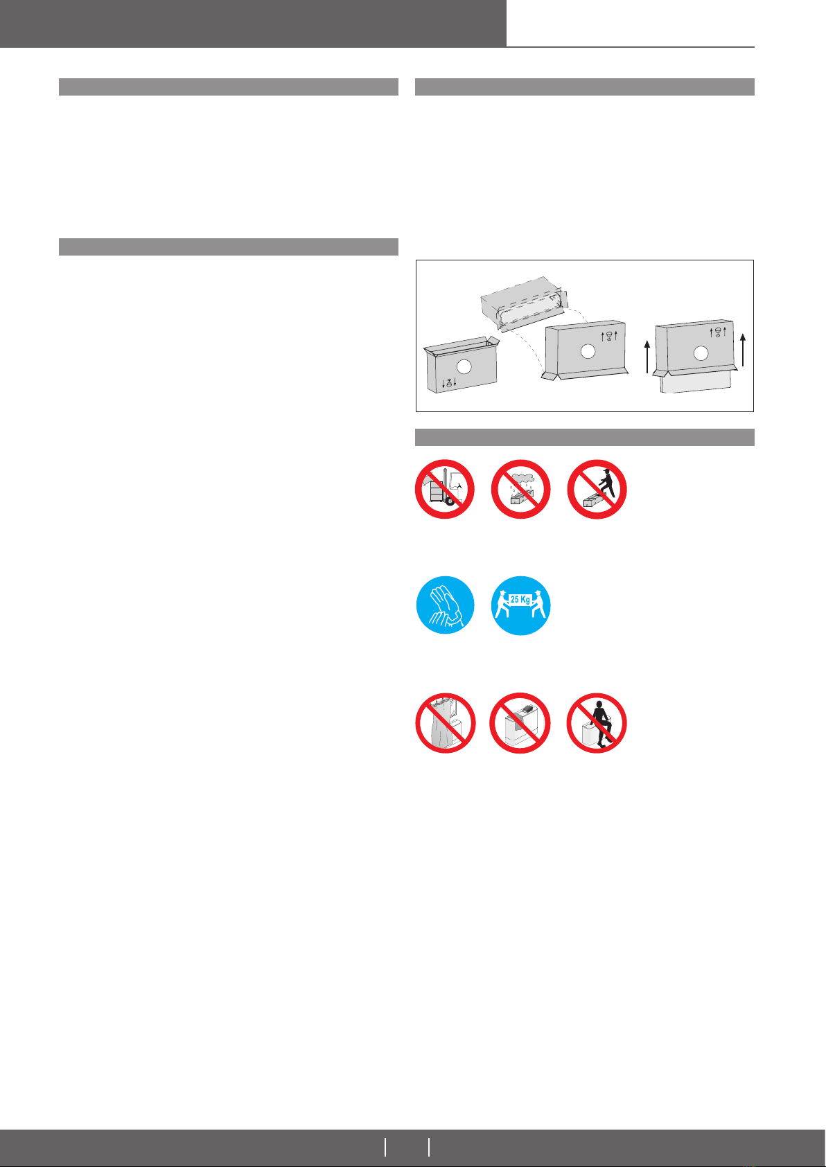
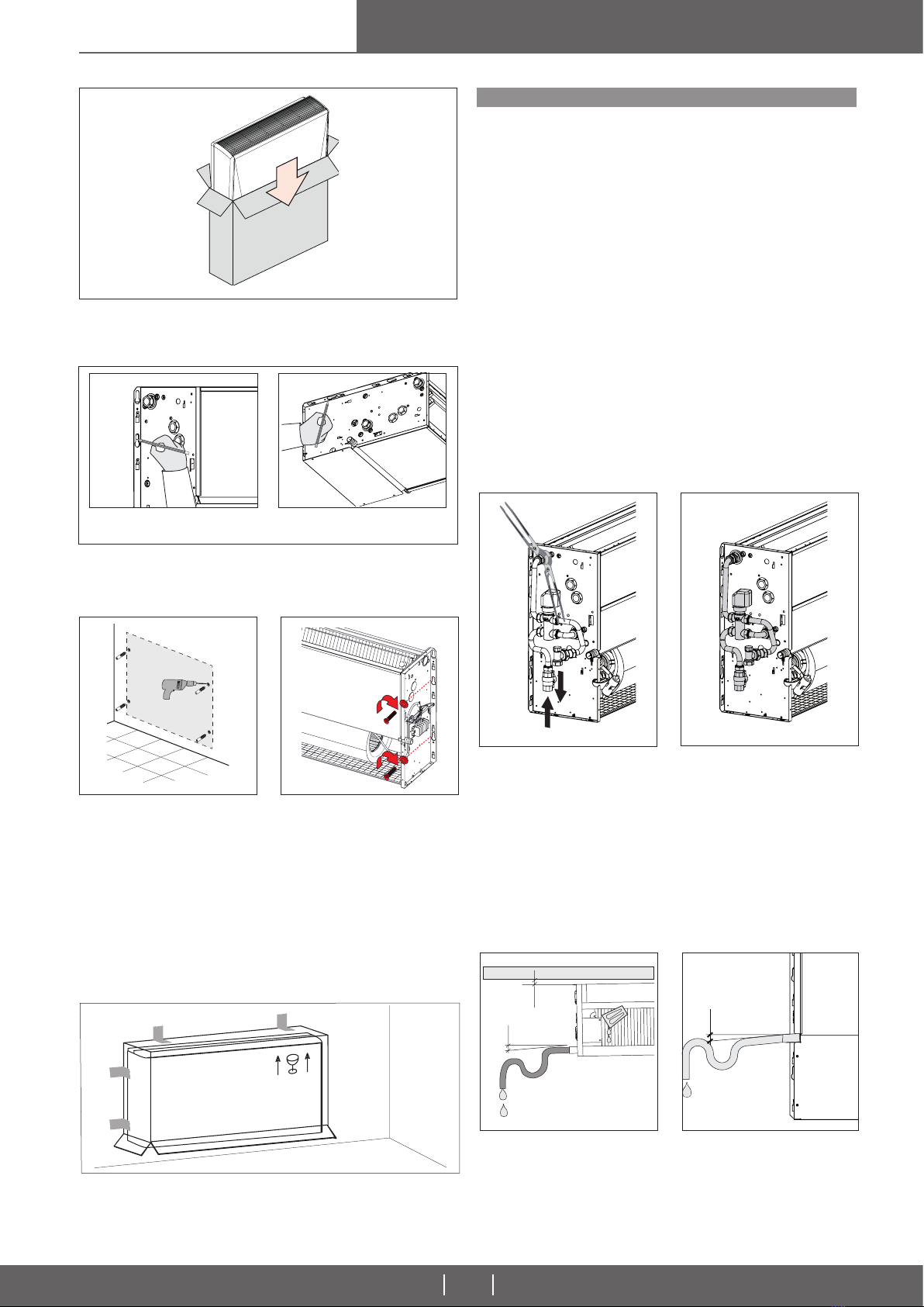
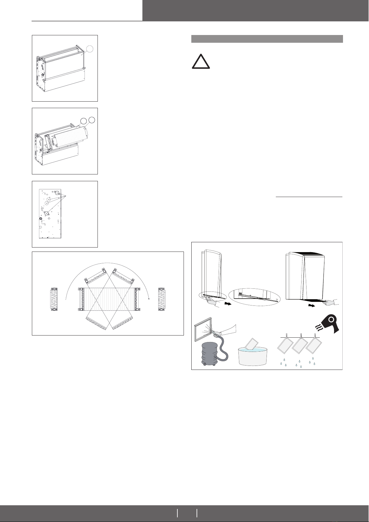
To take the appliance out of the packaging, proceed as Pic. 1:
1. Turn the fan coil box upside down and open the bottom.
2. Remove the polystyrene lling and keep it.
3. Keeping the bottom of the box open, turn the pack 180°, taking care that
the contents are rmly hald before resting it gently on the ground. Lift off the
packaging from the appliance.
Secure packs during transportation.
Do not expose to the elements.
Do not tread on packs.
Pic. 01
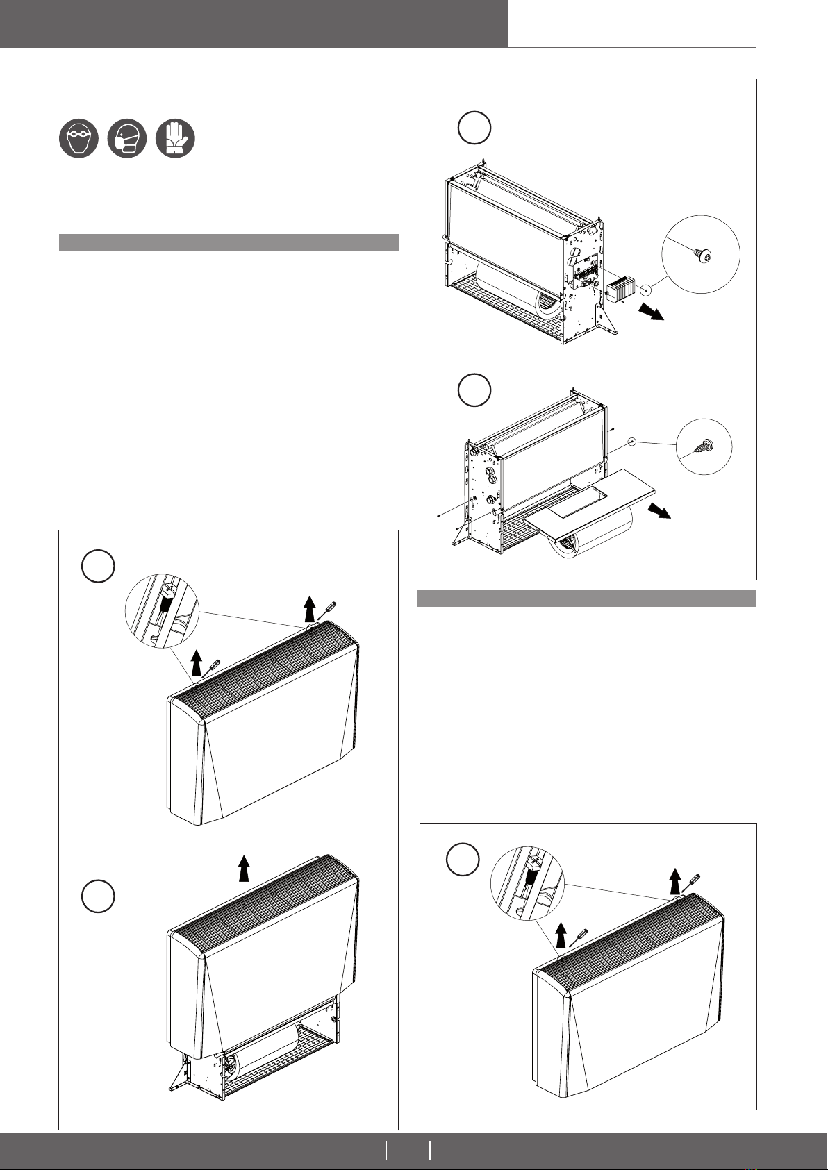
Protect hands with work gloves when dismantling the appliance.
Work in PAIRS if the applinance weighs more than 25 kg.
The appliance is easy to use, ut it is important to read this guide completely
before using for the rst time.
This will help you:
- use the appliance in all safety;
- obtain best performance;
- avoid errors;
- respect the environment.
- Do not allow children or unassisted handicapped persons to use the
appliance.
- Do not touch the appliance with wet parts of the body or if barefoot.
- Do not tug, pull or twist electrical cables attached to the appliance, even when
disconnected from the electricity supply.
- Do not open the aps giving access to the internal parts of the appliance wi-
thout having rst put the system on-off switch to “off”.
- Do not introduce sharp pointed objects through the air intake and outlet grilles.
- Do not leave packing material (cardboard, staples, plastic bags, etc.) within
reach of children since they could be a source of danger.
- Dispose of correctly.
- Do not sit or climb on the appliance or rest any type of object on it.
- Do not spray or throw water directly on the appliance.
- Do not use the appliance in places with suspended dust/powder or in poten-
tially explosive atmospheres, in very damp environments or in the presence of
oil in suspension or in particularly aggressive atmospheres.
- Do not cover the appliance with objects or drapes that even partially obstruct
the air ow.
- The appliance works by electricity at mains voltage (230 Vac, 50 Hz). Always
bear in mind that mains voltage is potentially dangerous and any appliance
connected to it should be used with caution. Before carrying out any work on the
appliance, disconnect it from the electricity supply (by pulling out the plug from
the mains socket or isolating the supply line by putting the on-off switch to off).
- If the appliance is not to be used for long periods, make sure that the controls
are in the position 0 (off). If the appliance is not going to be used in winter when
temperatures are near to freezing, drain the system and ensure that the applian-
ce heat exchanger has no water in it in order to prevent the formation of ice and
consequent breakage.
- To make the appliance inoperable, disconnect it totally from the electricity supply.
- It is unsafe to alter or try to alter the characteristics of this product. Any tampe-
ring or alteration renders the warranty null and void.
- In the event of malfunction or failure, do not try to repair the appliance yourself;
contact a qualied technician. Repairs carried out by unqualied persons could
cause damage or accidents.
- Always keep the appliance clean. In particular clean the air lter periodically
(at least once a month).
FAILURE TO COMPLY WITH THE ASSEMBLY INSTRUCTIONS GIVEN IN
THIS GUIDE RELIEVES THE MANUFACTURER OF ALL AND ANY LIABILI-
TY. INCORRECT INSTALLATION COULD CAUSE MALFUNCTIONING OR
FAILURE OF THE APPLIANCE. COULD ALSO REPRESENT A HAZARD
FOR THE USER.
1
23
CAUTION!
This appliance should only be used by adults. Make sure that children do not
touch the controls or play with the appliance. This appliance has been designed
for use as a heating and cooling appliance in rooms that are clean and frequen-
ted by persons (with normal pollution). Avoid using for any other purpose. This
appliance should not be used in places with suspended dust/powder or in po-
tentially explosive atmospheres, in very damp environments or in the presence
of oil in suspension or in particularly aggressive atmospheres.

INSTALLATION, USE,
MAINTENANCE MANUAL
Vers. 2018-0
centrifugal fan coil unit
5
GENERAL DIMENSIONS
DIMENSIONAL CHARACTERISTICS
Pic. 02
* NOTE: the dimensions shown are referred at system with left hydraulic connections
Power supply: 230V / 1ph / 50Hz ± 10%
2 PIPE SYSTEM MOD. 10 20 30 40 50 60 70 80 90 100
Fans number n° 1 1 1 2 2 2 2 3 4 4
Coils numbers n° 1 1 1 1 1 1 1 1 1 1
Coil used for
cooling and
heating
Rows number n° 3 3 3 3 3 3 3 3 3 3
Water content litri 0,5 0,8 1,2 1,5 1,8 2,1 2,4 2,4 2,7 3,1
Hydraulic connection (Ø Gas female) Ø 1/2” 1/2” 1/2” 1/2” 1/2” 3/4” 3/4” 3/4” 3/4” 3/4”
General
features
Unit lenght with cabinet L (mm) 600 750 900 1050 1200 1350 1500 1500 1650 1800
Unit lenght without cabinet M (mm) 380 530 680 830 980 1130 1280 1280 1430 1580
2 PIPE SYSTEM MOD. 10 20 30 40 50 60 70 80 90 100
Fans number n° 1 1 1 2 2 2 2 3 4 4
Coils numbers n° 1 1 1 1 1 1 1 1 1 1
Coil used for
cooling and
heating
Rows number n° 4 4 4 4 4 4 4 4 4 4
Water content litri 0,7 1,1 1,6 2,0 2,4 2,8 3,2 3,2 3,7 4,1
Hydraulic connection (Ø Gas female) Ø 1/2" 1/2" 1/2" 3/4" 3/4" 3/4" 3/4" 3/4" 3/4" 3/4"
General
features
Unit lenght with cabinet L (mm) 600 750 900 1050 1200 1350 1500 1500 1650 1800
Unit lenght without cabinet M (mm) 380 530 680 830 980 1130 1280 1280 1430 1580
4 PIPE SYSTEM MOD. 10 20 30 40 50 60 70 80 90 100
Fans number n° 1 1 1 2 2 2 2 3 4 4
Coils numbers n° 2 2 2 2 2 2 2 2 2 2
Coil used for
cooling
Rows number n° 3 3 3 3 3 3 3 3 3 3
Water content litri 0,5 0,8 1,2 1,5 1,8 2,1 2,4 2,4 2,7 3,1
Hydraulic connection (Ø Gas female) Ø 1/2” 1/2” 1/2” 1/2” 1/2” 3/4” 3/4” 3/4” 3/4” 3/4”
Coil used for
heating
N. rows n° 1 1 1 1 1 1 1 1 1 1
Water content litri 0,1 0,2 0,3 0,4 0,5 0,6 0,6 0,6 0,7 0,8
Hydraulic connection (Ø Gas female) Ø 1/2” 1/2” 1/2” 1/2” 1/2” 1/2” 1/2” 1/2” 1/2” 1/2”
General
features
Unit lenght with cabinet L (mm) 600 750 900 1050 1200 1350 1500 1500 1650 1800
Unit lenght without cabinet M (mm) 380 530 680 830 980 1130 1280 1280 1430 1580
110
233
122
135 135
A
L
25
3535
509
192
218
529
243 200
36
342
10438
123 18
20
25
14
190
210

INSTALLATION, USE,
MAINTENANCE MANUAL Vers. 2018-0 centrifugal fan coil unit
6
RECOMMENDATIONS FOR INSTALLATION
FAN COIL INSTALLATION
Before installing the appliance, ensure that:
1) the place of installation has sufcient space for carrying out installation as
well as routine and extraordinary maintenance work (see Pic. 4).
2) There are no obstructions for air intake and delivery.
3) The water connections are of the sizes, in the position and spaced apart as
required by the appliance (see Dimension).
4) The system pressure does not exceed 8 bar for the water versions.
5) The electricity supply corresponds to the data on the appliance rating plate
and that there is a afety switch readily accessible to the user to cut off the power
supply whenever necessary.
6) The safety switch is in the OFF position so that there is no voltage on the
appliance supply line.
Before installing the appliance, remove the cabinet, if present (Pic.5) and put it
in the packing box to prevent it from being soiled or damaged. (Pic.6)
130 mm
150mm
150mm
150 mm
Pic. 04
MAIN COMPONENTS
1Heat exchanger
2Water low temperature sensor
3Drain pan
4Air lter
5Electric motor
6Centrifugal fan
7Condense discharge
8Valves
9Auxiliary drain pan
10 Cabinet
11 Bearing structure
12 Terminal board
13 Supply grills
4
5
3
8
9
13
10
6
7
2
12
11
1
Pic. 05
Pic. 03
1
2

INSTALLATION, USE,
MAINTENANCE MANUAL
Vers. 2018-0
centrifugal fan coil unit
7
Offer the appliance up to the required point of installation and mark, through the
xing holes, the points on the wall where the holes should be driller for the 4
screw anchors, as shown in Pic. 7.
Remove the appliance from the point of installation, drill the holes where merked
on the wall (see Pic. 8) and insert the screw anchors. Place the appliance against
the wall and x it by tightening the screws into the anchors see (Pic. 9).
Pic. 06
Pic. 07
Vertical version Horizontal version
Carry out the water and electrical connections as described in the relevant pa-
ragraphs.
Replace the housing using the opposite procedure to take off the cabinet (Pic.
05)
Pic. 08 Pic. 09
The cabinet is covered by a protective lm: remove it before xing it to the
unit. Replace the cabinet (if tted), otherwise the appliance must be masked by
the customer.
WARNING! Protect the appliance with a cardboard if the building works of the
building are still to be closed (Pic 10).
Remember to remove the protective cardboard before starting the equipment.
Pic. 10
WATER CONNECTIONS
CONNECTION TO THE WATER MAINS
CAUTION! Always use a wrench and nose key for connection of the coil
to the pipes (Pic. 11). If the solenoid valve is installed, suitably insulate the
valve body with insulating material (Pic. 12).
Connect the water inlet and outlet pipes, observing the indications given on the
side of the appliance. Correctly insulate the water supply pipes to prevent drip-
ping during the cooling mode of operation. An shutoff valve should be inserted
on the water supply pipe and balancing valve on the outlet pipe. The valve body
and balancing valve should also be properly insulated to prevent dripping. It is
the installer’s responsibility to insulate properly and the manufacturer cannot be
held liable for any insulation work.
NOTE: it is always advisable to install the solenoid valve. In the heating
mode of operation the solenoid valve reduces consumption because upon
reaching the set temperature the circulation of water is stopped to avoid
wasting energy (the fan coil would otherwise continue to heat like a radia-
tor, even with the motor at a standstill). In the cooling mode of operation
the solenoid valve stops the circulation of water when the set temperature
is reached, this stopiing the internal exchanger
from continuing to condense water with possible undersirable dripping
into the oor. It also reduces chiller operation with consequent energy
saving.
Pic. 11 Pic. 12
3 cm/m
CONDENSATE WATER DRAINAGE
The condensate drain pipe should slope downwards by at least 3 cm/m and
should not have ascending or throttled section in order to ensure a regular ow
of water. It is advisable for a trap to be tted. The condensate drain pipe should
be connected to a rainwater drainage system. Do not use sewage system to
avoid possible odours in the event of evaporation of the water in the trap. Upon
completion of work, check that the condensate ows out properly by pouring
water into the tray (see Pic. 13 and 14). The condensate water drainage system
should be fabricated
in a workmanlike manner and should be periodically checked. The manufacturer
cannot be held liable for any damage caused by dripping in the absence of a
solenoid valve or of periodic maintenance of the drainage system.
Pic. 14Pic. 13
3 cm/m
5 mm

INSTALLATION, USE,
MAINTENANCE MANUAL Vers. 2018-0 centrifugal fan coil unit
8
ELECTRICAL CONNECTIONS
CONNECTIONS TO THE TERMINAL BOARD
RECOMMENDATIONS!
Before carrying out electrical connections, ensure that the electricity supply to
the supply line has been cut off, checking that the on-off switch is in the OFF
position. Only qualied electricians should carry out the electrical connections.
Check that the mains supply is single-phase 230 Vac/1/50 Hz (± 10%).
Operating the appliance with voltages outside the above limits could cause mal-
function and renders the warranty null and void.
The fan coil power supply line should be tted with at least a switch isolator in
conformity with European standard EN60947-3. Make sure that the electrical
system is suitable for providing not only the working current required by the
appliance, but also the necessary current for powering household and other
electrical appliances already in use.
Any electrical and mechanical alterations or tampering render the warranty null
and void. The motor and accessories power cables in channels or ducts should
remain inside the same until they are inside the appliances.
The cables should be sufciently long so that they are not permanently taut or
create throttling or pressure on metal parts (see Pic. 16). The power cables
should be sufciently long so that in the event of accidental tugging the active
wires are subjected to stress before the earth wire. Connect the earth wire to the
relative terminal marked with the symbol .
Check the earth connection. Comply with the safety regulations in force in the
country of installation.
WITHOUT CONTROL PANEL
The electrical connections should be made to the terminal board on the side of
the appliance.
Each terminal is identied by the label to be found on the terminal board.
WITH CONTROL PANEL
The electrical connections should be made directly to the control panel, as shown
by the relative wiring diagram. If the control panel has an electronic temperature
sensor (NTC) this sensor will be powered by mains voltage (230Vac/1/50 Hz)
and is therefore provided with double insulation.
CAUTION: FAILURE TO COMPLY WITH THE INDICATED CONNECTIONS
MAY CAUSE MOTOR BURNOUT!
CHANGING THE MOTOR SPEED OF ROTATION
(STANDARD MOTOR ONLY)
TURNING THE COIL
TESTING THE FANCOIL
The fan coil motor has 6 speed settings, 3 of which are connected in the fac-
tory (red, blue and black wires connected to the motor auto-transformer). To
use other speeds than those wired up in the factory, the red (minimum), blue
(medium) and black (maximum) wires may be connected onto 3 of the 6 num-
bered terminals (1…6), taking into account that the speeds follow a sequence
as shown in Pic. 15.
* CAUTION!
UNDER NO CIRCUNSTANCES SHOULD THE CONNECTIONS TO THE TER-
MINALS L, M, M BE CHANGED!
CAUTION!
The fan may reach the speed of 1,000 rpm. Do not insert objects or hands into
the electric fan. The motor becomes hot during operation; wait for it to cool
before touching it. During the heating mode of operation the exchanger and the
connecting pipes may become very hot (80°C).
Wait for the exchanger to cool before touching it or protect hands with
suitable gloves. The heat exchange water coils are suitable for working up
to ma maximum pressure of 8 bar.
To turn the coil, proceed as follows:
A) Remove the housing (if present).
B) Remove indicate screws in picture:
- 1,2: standard coil screws;
- 3: auxiliary coil screws;
- 4,5: main drain pan screws;
- 6,7: motor screws.
C) Disconnect the terminal block or the
control panel (2), if present, from the side
of the appliance;
Upon completion of installation, scrupulously check both the water and the elec-
trical connections before switching on the appliance.
Before mounting the housing (if present), ll the system, bring it up to pres-
sure and bleed. Make the water circulate and check for leaks.
Check correct operation of the fan coil at the 3 speeds, of the solenoid
valves and of the minimum temperature thermostat (if installed).
Pic. 15
Pic. 16
Rosso
Blu
Nero
Motore (*)
Motore (*)
Comune
1
2
3
4
5
6
7
WORK LIMITS
THE UNITS HAVE THE FOLLOWING OPERATING LIMITS:
- IT CAN’T BE INSTALLED IN AREAS WITH ANOMALOUS HEAT AND HU-
MIDITY CONDITIONS;
- IT CAN’T BE INSTALLED OUTDOORS;
- IT CAN’T BE INSTALLED IN EXPLOSIVE ENVIRONMENTS;
- IT CAN’T BE INSTALLED IN A CORROSIVE ATMOSPHERE.
SUMMER (COOLING)
Minimum inlet water temperature +4°C
Maximum operating pressure 8 bar
Maximum room air temperature +35°C
Maximum room air humidity 80%
WINTER (HEATING)
Maximum inlet water temperature +80°C
Maximum operating pressure 8 bar
Minimum room air temperature +4°C
Maximum room air humidity 80%
Maximum room air temperature +35°C

INSTALLATION, USE,
MAINTENANCE MANUAL
Vers. 2018-0
centrifugal fan coil unit
9
D) Take out drain pan (A).
Pic. 17
Pic. 18
Pic. 19
Pic. 20
A
180°
E) Take out auxiliary coil (C), if present,
and standard coil (B).
Prestare attenzione a non tagliarsi con
le alette e a non danneggiarle.
F) Remove the knockouts (6) on the oppo-
site side of the fan coil (using a screwdri-
ver), to allow the coil connections to pass
through.
G) Position the coil, turning it of 180°, so that the ttings are in line with the holes
left by the knockouts. Fix the coil using the previously removed screws.
H) Shift the control panel, if present, or the terminal block (xing it to the side
opposite the water ttings), the motor and sensor cables, if present, xing them
with their grips. Ensure that the cables pass through the hole in the side of the
appliance, protecting them with the relative grommet. If it proves easier to carry
out this operation by separating the wires from the terminal blocks, mark the
positions of the wires to avoid making mistakes when reconnecting.
I) Reconnect the wires to the relative terminal blocks or control panel, taking
care that they are correctly positioned.
L) Reassemble the components previously removed and follow the steps A, B,
C, D, E, on the contrary.
ATTENTION:
Copper ttings for valve are different between right and left installation.
If hydraulic connections have to be modied on site, it’s necessary to order the
correct installation kit.
KNOCKOUTS
B
C
CLEANING AND MAINTENANCE
ATTENTION!
1) THE FILTER MUST BE KEPT CLEAN
2) CLEAN THE FILTER MAXIMUM FOR TWO TIMES AND THEN
REPLACE IT. FURTHER FILTER MUST BE REPLACED WITH A
NEW ON AT LEAST EVERY 12 MONTHS
CAUTION! Before carrying out any cleaning or maintenance work, discon-
nect the appliance from the mains electricity supply!
ORDINARY MAINTENANCE
For standard use of the unit in normal condition we recommend:
- to clean the housing;
- to clean the coil;
- to clean the drain tting (check the normal condensate ow).
CLEANING THE AIR FILTER
The appliance is tted with an air lter on the fan inlet. During normal operation
the lter withholds impurities in the air.
The lter should be cleaned periodically to keep its ltering properties and the
airow to the fan unchanged. It is advisable to clean the lter as follows:
1. Take out the lter.
2. Place the lter on a at, dry surface and remove the accumulated dust with
a vacuum cleaner.
3. Wash the lter with dedicated detergent approved for hygienic applications
(no solvents).
4. Replace the lter when it is perfectly dry only.
CLEAN THE FILTER MAXIMUM FOR TWO TIMES AND THEN REPLACE IT.
FURTHER FILTER MUST BE REPLACED WITH A NEW ONE AT LEAST EVE-
RY 12 MONTHS
Pic. 21
DEDICATED
DETERGENT
NOTE
The procedure for ceiling-mounted horizontal version is the same.
!

INSTALLATION, USE,
MAINTENANCE MANUAL Vers. 2018-0 centrifugal fan coil unit
10
REMOVE THE MOTOR PLATE (STEP #1)
REMOVE THE DRAIN PAN (STEP #2)
Caution Before performing any work on the unit, make sure that the unit is
not powered. It is important to be aware that there is a risk of injury due to the
rotation of the impeller. Make sure the unit is properly secured against the next
start using a device placed on site.
Remove the protective cover of the terminal board. Disconnect the power
cables and the (last) ground line of the motor. Remove the cable by passing it
through the cable gland positioned on the shoulder.
Remove the 2 + 2 screws on the side of the machine with the help of a
screwdriver (2 on the right and 2 on the left as shown in the gure). Hold the
engine during operation.). Remove the motor in drawer mode (see Pic. 22).
Clean it using a cotton cloth and a ph acid detergent (it is advisable either to
blow it carefully in an open environment or to vacuum the deposited powders
before cleaning it).
Reassemble the engine and fasten it to the machine frame. Pass the power
cable through the fairlead and connect the terminals in the same position.
Replace the terminal board and reposition the terminal block cover.
Before feeding, make sure that the motor impeller is free to turn freely.
CAUTION
Removing the condensate drain pan connection will make it easier to
remove the pan.
Remove the 2 + 2 screws on the side of the machine with the aid of a screwdriver
(2 on the right and 2 on the left as shown in the Pic. 23)
Remove the condensate drain pan by turning it slightly forward (P1) and pulling
it (P2). In the operation, pay the utmost attention not to damage the insulating
material.
Clean the underlying part of the exchanger that is part of the motor plate;
eliminate any traces of dust or deposits. Help with the operation with a cotton
cloth and an acidic ph detergent. If necessary, use a brush with metal brushes
to remove any deposits in the fold edges and corners.
Reassemble the condensate drain pan and at the end of the operation verify
the restoration of the functionality.
1
1
2
3
4
To perform all the steps shown, wear the individual protective devices: protective
glasses, masks and anti-cut gloves.
It is advisable to have the cleaning operations carried out by suitably trained
personnel.
The disinfestation to personnel in charge and appropriately prepared and
equipped with specic requirements.
Pic. 22

INSTALLATION, USE,
MAINTENANCE MANUAL
Vers. 2018-0
centrifugal fan coil unit
11
REMOVE THE HEAT EXCHANGER (STEP #3)
CAUTION
To remove the exchanger, disconnect the unit from the hydraulic line.
To facilitate this operation, the installation of shut-off valves is always
recommended.
Remove the terminal board to access the heat exchanger xing screws.
Remove the 2 + 2 screws on the side of the machine with the aid of a screwdriver
(2 on the right and 2 on the left as shown in the Pic. 24) screws that secure
the frame of the exchanger to the shoulder. Extract the exchanger by making a
slight rotation of the same on the opposite side of the joints.
Remove the exchanger and clean it (it is advisable to blow it carefully in an
open environment or to vacuum the deposited powders before cleaning it).
Handle the exchanger very carefully to avoid damaging it and compromising
the exchange efciency and therefore the capacity.
Reassemble the exchanger and before installing the screws, insert the
condensate drain pan.
Fix the exchanger screws.
2
3
1
2
3
4
5
Pic. 23
Pic. 24

Vers. 2018-0
12
DISMANTLING THE APPLIANCE
This appliance is made to last for many years. Qualied personnel are needed
to dismantle it in all safety. The rst operation to be carried out before disman-
tling the appliance is to disconnect it totally from the electricity supply.
This appliance has been made using recyclable materials (copper, aluminium,
brass, plastic) assembled by screws and push-ts to make separation of the
parts easy.
Contact a rm specialised in differentiated waste disposal; it is the only way
to be certain of correct recycling and thereby contribute to protection of the
environment.
INSTALLATION, USE,
MAINTENANCE MANUAL centrifugal fan coil unit
WHAT TO DO IF...
The fan does not work
Possible cause: power failure
Possible remedy: check the on/off switch
Possible cause: switch in position “0”
Possible remedy: change position on the control panel
Possible cause: water in the system not hot enought
Possible remedy: check that the outlet temperature is above 40°C
Little outowing air
Possible cause: clogged lter
Possible remedy: clean the lter
The appliance does not heat
Possible cause: no hot water in the system
Possible remedy: check that the boiler and circulating pump are
working
Possible cause: Incorrectly positioned hot/cold switch
Possible remedy: check that the switch is on for heating and for
cooling.
The appliance does not cool
Possible cause: no cold water in the system
Possible remedy: check that the chiller and the circulating pump are
working
The appliance heat/cool very little
Possible cause: incorrectly regulated thermostat
Possible remedy: turn the thermostat knob (if installed) left/right
Possible cause: air in the pipes
Possible remedy: bleed by loosening the valve at the heat exchanger
inlet
Water on the oor during cooling
Possible cause: blocked condensate drain
Possible remedy: switch off the appliance and contact the installer to
check condensate drainage
PEST CONTROL PHASE
For the total disinfection of the unit, remove the motor complete with plate as
described in “STEP #1”.
Remove the pan as described in “STEP #2”.
Remove the exchanger as described in “STEP #3”.
CLEAN THE PARTS IN DIRECT CONTACT WITH THE AIRFLOW
Use a detergent with acid pH to remove any calcareous deposits, while the use
of an alkaline pH detergent is recommended if there are greasy areas of dust
or oil.
CLEANING PHASE AND FILTER REPLACEMENT
Filter cleaning; extract the lter and blow it carefully in an open environment or
aspirate the deposited powders.
Clean the lter thoroughly, dry it.
Disinfect it, dry it and install it.
Thoroughly clean the tracks (binari di alloggiamento)
The lter can be cleaned a maximum of two times, after which it is recommen-
ded to replace the lter.
Replace the lter and carefully clean the housing seats of the same every six
weeks after starting up the appliance.
Record the operations carried out with relative intervention dates and the name
of the operator in the appropriate register.

NOTE

NOTE


With the perspective of improvement, and against the continuous action of research and development,
the Manufacturer might modify, even without any prior notice, the given technical data.
MI_AIR_HYGIENIC_2018-1-0_EN
This manual suits for next models
20
Table of contents
Popular Fan manuals by other brands

Salda
Salda RIS 400HW Technical data

Venture Industries
Venture Industries RF OPERATION AND MONTAGE MANUAL

UNITED
UNITED UBF-655 instruction manual

Westinghouse
Westinghouse WSFS1808BK instruction manual

Wilo
Wilo Yonos Para RS 25/6 Installation and use manual

Reflex
Reflex Exvoid T Series Instructions for use