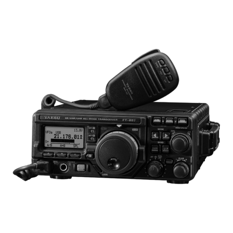
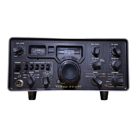
Yaesu FT-101E User manual

—YAESU-
MUSEN
oe

SSB
TRANSCEIVER
wn
Ee
ee
powen HIATT
got
cee
eT
alia
Hes
P|
peeee
@)
ong
s
Le
—.
$
2
AF
Gee
OA
or
ie
a
1
f
‘a
oy
S$
i
.
h
gEwel
a“
Bary
i
~
i
a
log
ay
=
‘
Pi,
Ba
7
F
i
==
a
iat
wy
an
L
He
re
ue
GENERAL
DESCRIPTION
The
model
FT-IO1E/277E
SSB
Transceiver
is
a
precision
built,
compact
high
performance
transceiver
of
advanced
design
providing
SSB
(USB,
LSB
selectable)
CW
and
AML
modes
of
operation.
The
transceiver
operates
at
an
input
of
260
watts
SSB,
180
watts
CW
and
&0
watts
AM
on
all
bands
160
to
10
meters
All
circuits,
except
the
transmitter
driver
and
linear
amplifier,
are
transistorized
and
composed
of
standard
computer
type
plug-in
modules,
permiting
easy
main
tenance
The
transeever
1.
self-contained,
requiring
only
an.
an
lenna
and
an
AC.
mains
for
home,
portable
or
mobile
oper-
ation.
The
transeener
may
be
operated
from
TOOTTO:
117
/200/220/234
volts
AC
when
appropriately
wired
but
18
normally
supplied
for
117
volt
AC
and
12
volt
DC
operation,
The
twoway
solid
state
power
supply
is
an
integral
part
of
the
umt.
Two
power
cords.
are
provided
with
the
transceiver;
Selection
of
AC
or
DC
power
source
1s
automatically
made
when
the
proper
line
cord
plug
is
inserted.
For
mobile
operation
a
separate
switch
is
provided
on
the
front
panel
to
turn
off
the
tube
heaters
while
in
the
receive
mode,
In
this
mode
the
transceiver
clraws
only
0.5
amp.
less
than
your
auto
dash
lights
All
accessories,
such
as
VOX,
break-in
CW
with
side
tone,
25
and 100
KHz
calibrators,
noe
blanker,
10
MHz
WW
are
built-in.
In
addition
,
dual
VFO
adaptor,
erystal
control
adaptor,
speaker
and
clarifier
are
integral
parts
of
the
unit.
Provision
is
made
for
the
installation
of
600
Hz
ervstal
filter
for
the
expert
CW
DA
operator,
The
CW
filter
is
selected
automatically
when
the
transceiver
mode
switch
1
placed
in
the
CW
position,
The
entire
transceiver
weighs
approximately
40
pounds,
is
13
1/2"
wide,
6"
high,
11
1/2"
deep.
Construction
if
of
heavydauge
steel
which
provides
an
extremely
rugged
package,
virtually
immune
to
the
effects
of
vibration
and
shock
The
SP
101PB/277PB
combination
phone
patch
and
ex:
ternal
speaker.
is
a
valuable
optional
accessory
for
base
operation,
[Che
unit
features
an
elliptical
type
speaker
for
high
quality
voice
reproduction.
Other
optional
equipment
includes
the
FPV-LOLB/2Z776
external
VFO
and
mobile
mounting
brackets.
|
—

SPECIFICATIONS
FereQuency:
(RANGE:
ccc
-ceieeots
ecentecevadsyateed
stapes
iabederea
teat
in
mashes
1.8~29.9
MHz
amateur
bands,
(160
thru
10m)
26.9~
27.5MHz,
10~10.5MHz
Receive
only
Type
Of
Emission’
ves
ces.ccesescesootee
Soa
dcesesdevecescdedechetveceveccesduses
USB
or
LSB
(selectable)
CW,
AM
Pee
Hatake
ennces
nscttctew-tatettcones
anoeneines:
‘SSB
260
Watts
PEP
CW
180
Watts
50%
duty
cycle
AM
80
Watts
(slightly
lower
on
10
meters)
Carrier
SUpPPreSSiON
........ccccccccccccceessssssessteceeecesceseseeeeeeeeeeaes
50
db
Sideband
Suppression
.....cccccccsccescecessceeeeeseseeseceeeseeeeeeenaes
50
db
at
1000
Hz
Sptirious
Radiation
scces.cieteahs
cee
bed
site
dad
ead
ated
ches
eee
Down
40
db
or
more
Transmitter
Frequency
>
Response
..........::cccsssscesseeseeeseeeeeeees
300
Hz
-
2700
Hz
+3
db
Distortion:
Products
‘siscccpesicsssccsecescsesdesecattusteaeaisceceacarcseessbaees
Down
30
db
or
more
Antenna
Output
Impedance
..........ccceeeesseeeceeseeeeesseeeeseeeees
50
-
75
ohm
unbalanced
Frequency
Stability
.......
cee
eeeseceeeseeseecrecsessesseereeesecseenees
Less
than
100
Hz
drift
in
any
30
minute
period
SOnSitiVit
ys
bscbncatecesdedelensiebcdvcobedsSushielabehonssousteresctaseaticeotsloie
cd
0.3
uV
S/N
10
db
SOLE
CEVILY:
ceive
s
aN
oSE
EA
toa
haat
Sake
eda
ost
ieee
ene
2.4
KHz
at
6
db)
eS
4.0
KHz
at
60
db)
SSB,
AM,
CW
(
(
(600
Hz
at
6
db)
oO
Kialeo
day
pee
Audio:
Output
ne.tipedlininna
anise
catnsehoneeae
3
Watts
Power
Consumption
.........::ccccccccsceessssssessssenseeeeeceessessteeeeees
AC
Receive
45
Watts
Transmit
350
Watts
Max.
DC
12V
Standby
0.6
Amp.
Transmit
21
Amps.
Max.
DIMONSiIOWS.
cts
gesec
selec
aeedie
dda
need
ode
dediel
Seidaadaanuts
dceseseaeeeneededes
13
1/2”
wide,
6”
high,
11
1/2”
deep
WO
iBhl:
decereteceves
sept
sacs
ended
dedeesueenacerene
Lath
een
ie
i
castegs
Approx.
30
Pounds
Ste
do
LO
te

INSTALLATION
The
transceiver
is
designed
to
provide
a
complete
single
unit
installation
for
fixed,
portable,
or
mobile
operation.
Two
prewired
plugs
are
furnished
with
the
unit
for
AC
or
DC
operation.
This
system
provides
the
flexibility
required
for
various
installa-
tions
and
allows
rapid
change
from
fixed
to
mobile
operation.
Base
Station
Installation
;
The
transceiver
is
designed
for
use
in
many
areas
of
the
world
using
supply
voltages
that
may
differ
from
the
operators
local
supply
voltage.
Therefore,
before
connecting
the
AC
cord
to
the
power
outlet,
be
sure
that
the
voltage
marked
on
the
rear
of
the
transceiver
agrees
with
the
local
AC
supply
voltage.
CAUTION
Permanent
damage
will
result
if
improper
AC
supply
voltage
is
applied
to
the
trans-
ceiver.
The
transceiver
should
be
connected
to
a
good
ground.
The
ground
lead
should
be
connected
to
the
terminal
marked
GND
located
on
the
rear
panel
of
the
trans-
ceiver.
Mobile
Installation
;
The
transceiver
will
operate
satisfactorily
from
any
12
volt
negative-ground
battery
source
by
connecting
the
DC
power
cord
to
the
rear
panel
receptacle.
For
under-dash
mounting,
a
special
mounting
bracket
is
available
from
your
dealer.
A
location
should
be
selected
clear
of
heater
ducts.
No
special
mounting
pre-
cautions
need
be
observed
if
adequate
ventilation
space
is
available.
A
minimum
of
two
inches
of
air
space
above
the
cabinet
top
and
on
all
sides
is
recommended
to
allow
proper
air
flow
around
the
cabinet.
Never
stack
other
units
above
or
below
the
cabinet
since
the
accumulated
heat
from
both
units
could
cause
perma-
nent
damage.
The
transceiver
requires
an
average
of
14
amps
on
transmit
and
20
amps
on
voice
peaks.
The
fuse
in
the
DC
power
cable
should
be
rated
at
20
amps.
When
making
connections
to
the
car
battery,
be
certain
that
the
RED
lead
is
connected
to
the
positive
(+)
terminal
and
the
BLACK
lead
to
the
negative
(—)
terminal
of
the
battery.
Reversed
connections
could
permanently
damage
the
transceiver.
The
BLACK
lead
should
run
directly
to
the
negative
terminal
of
the
battery.
Using
the
car
frame
as
a
negative
connection
or
connecting
the
positive
lead
at
a
point
such
as
the
ignition
switch
places
the
devices
creating
noise
in
the
same
current
path
as
the
transceiver
and
fails
to
take
advantage
of
the
filtering
action
of
the
battery.
The
power
cable
should
be
kept
away
from
ignition
wires
and
be
as
short
as
possible
to
minimize
voltage
drop
and
to
provide
a
low
impedance
path
from
the
transceiver
to
the
battery.
Prior
to
operating
the
transceiver
in
a
mobile
installa-
tion,
the
voltage
regulator
setting
should
be
checked.
In
many
vehicles,
the
voltage
regulations
is
very
poor
and
in
some
cases,
the
regulator
may
be
adjusted
for
an
excessively
high
charging
voltage.
As
the
battery
and
regulator
age.
the
maximum
voltage
while
charg-
ing
can
increase
to
a
very
high
level
which
is
in-
jurious
to
the
battery
and
could
cause
damage
to
the
transceiver.
The
transceiver
is
designed
to
operate
from
a
source
voltage
range
of
11
to
14
-volts.
It
is
necessary
to
carefully
set
the
regulator
so
that
the
highest
charg-
ing
voltage
does
not
exceed
14
volts.
The
transceiver
should
be
switched
“OFF”
when
vehicle
is.
started
to
prevent
voltage
transcients
from
damaging
power
supply
transistors.
Antenna
;
CAUTION
Never
transmit
without
having
proper
antenna
or
dummy
load
connected
to
the
transceiver
The
transceiver
is
designed
for
use
with
resonant
anten-
na
having
an
impedance
50-75
ohm
resistive
load.
The
antenna
is
usually
the
most
critical
part
of
a
station
installation.
Results
both
in
receiving
and
trans-
mitting
will
depend
on
how
well
the
antenna
is
installed
and
adjusted.
Any
of
the
common
antenna
systems
designed
for
use
on
the
high
frequency
amateur
bands
may
be
used
with
the
transceiver,
provided
the
input
impedance
of
the
antenna
system
is
within
the
capa-
bility
of
the
transceiver
pi-matching
network
(50-75
ohms).
es
ee

If
a
tuned
open
wire
transmission
line,
or
a
long
wire
antenna
is
used,
a
suitable
antenna
tuner
must
be
used
between
the
antenna
and
the
transceiver
to
provide
an
impedance
match
between
the
unbalanced
coaxial
out-
put
of
the
transceiver
and
the
balanced
open-wire
feeder
or
Jong
wire.
For
mobile
operation,
most
of
the
commercially
availa-
ble
antennas
on
the
market
will
give
good
results
with
coaxial
cable
is
securely
grounded
to
the
chassis
of
the
vehicle
at
the
antenna
mount.
Adjust
the
antenna
length
carefully
for
minimum
SWR
after
installation.
INTERCONNECTIONS
FV-101B/277B
FT101E/277E
GND
1
O
°
SP-101PB/277PB
ANTENNA
TELEPHONE
LINE
INTERCONNECTION
DIAGRAM
MIC
PLUG
@
@
Q
@
MICROPHONE
CONNECTION
WARNING
SERIOUS
DAMAGE
MAY
RESULT
TO
THE
INVERTER
TRANSISTORS
IF
POWER
PLUG
OTHER
THAN
THOSE
SUPPLIED
WITH
THE
UNIT
ARE
UTILIZED.
CINCH
JONES
OR
OTHER
SIMILAR
U.S.A.
VERSION
CONNECTORS
WILL
FIT,
HOWEVER
THE
PIN
NUMBERING
SYSTEM
IS
DIFFERENT.

FTV-250/FTV-650B
(2/6
METER
TRANSVERTER)
FT101/201
FTV-650B
(NPUT
POWER
2
Cir
OD
ean
®
ley
D
|
ll
!
cofsloksfsiwlrole
JOO
FN 1D
Fn]
W]Nyo|

CONTROLS
AND
SWITCHES
The
transceiver
has
been
specifically
designed
for
ease
of
operation
and
versatility,
All
controls
have
been
preset
at
the
factory.
Several
of
the
controls
are
unusual
in
operation,
and
improper
adjustment
may
result
in
signals
of
poor
quality,
The
various
from
(1)
VFO
Select
Switch
:
This
switch
provides
selection
of
the
companion
FV-101B
external
VFO
or
two
fixed
crystal
oscillator
positions
Normal
operation
of
the
transceiver
VFO
requires
that
the
switch
be
placed
in
the
“INT”
pasition,
IN
T--
FT-101E/277E
VFO
controls
both
trans-
mitter
and
receiver
frequencies
RX
EXT-FV-101B/277B
EXTERNAL
VFO
controls
the
receiver
frequency
and
the
FT-101E/277E
VFO
controls
transmitter
output
frequency.
TX
EXT--FY-101B/277B.
EXTERNAL
VFO
controls
the
transmitter
output
frequency
and
the
FT-101E/
277EVFO
controls
the
receiver
frequency.
EXT:
FY-LOIB/277B
EXTERNAL
VFO
controls
both
transmitter
and
recerver
frequencies.
CHI,
CH2--Provides
crystal
control
of
the
transceiver,
Proper
ervstals
must
be
installed
on
PB-1494
crystal
oscillator
board,
for
ervstal
controlled
operation
(2)
MODE
Switch;
(LSB-USB-TUNE-CW-AM)
The
MODE
switch
is
a
five-position
switch.
This
switch
is
used
to
select
the
mode
of
operation;
LSB,
USB,
AM, CW,
or
TUNE
position,
In
the
AM,
CW
and
TUNE
position,
a
separate
crystal
is
used
to
shift
the
carrier
frequency
into
the
filter
passband,
(3)
RF
GATIN/AF
GAIN
;
The
RF
GAIN
and
AF
GAIN
controls
are
mounted
panel
controls
and
ther
functions
are
described
in
the
following
section.
Be
‘certain
that
you
understand
thoroughly
the
function
of
each
control
before
operating
the
transceiver,
an
concentric
shafts.
RF
GAIN
control
(lever
control}
varies
the
gam
of
the
receiver
RF
and
IF
amplifier.
Maximum
sensitivity
is
obtained
with
the
econtral
set
at
10}
{
fully
clackwise),
The
AP
GAIN
control
(round
knobij
adiusts
the
audio
output
level
at
the
speaker
and
phone
jack.
Clockwise
rotation
increases
the
audia
outpul.
(4)
Tuning
Knob
The
tuning
knob
located
directly
below
the
main
dial
window
in
combination
with
the
band
switch
determines
the
actual
frequency
of
operation,
The
VFO
drive
mechanism
consists
of
a
precision
spring
loaded
spht
gear
system
in
combination
with
a
planetary
drive
unit
to
provide
zero
backlash
at
low
tuning
rates,
Each
revolution
of
the
tuning
knob
results
ina
frequency
change
of
16
KHz
as
indicated
on
the
skirt
surrounding
the
tuning
knab,
(9)
BAND
Switch
;
The
band
switch
is
an
eleven-position
switch
used
to
select
the
desired
band
for
receiving
or
transmitting.
The
band
indication
is
color
coded
to
guide
tor
selecting
inthe
proper
frequency
scale
for
each
band.
(6)
(7)
CLARIFIER
;
The
clarifier
control
provides
a
means
for
tuning
the
receiver
trequency
3
KHz
to
either
side
of
the
transmitting
trequency.
Thus,
it
is
possible
to
set
the
pitch
of
the
voice
you
are
receiving
to
the
the
opera-
SSE

most
readable
point
without
affecting
your
trans-
mitting
frequency.
Its
use
is
particularly
valuable
in
“net”?
operation
where
several
participants
may
be
transmitting
slightly
off
frequency.
The
clari-
fier
control
functions
with
the
clarifier
switch
(7)
set
to
the
push-down
position,
and
a
red
warning
lamp
lights
up.
With
the
clarifier
switch
out
position,
the
red
lamp
turns
off
and
the
receiver
is
locked
to
the
transmitting
frequency.
Normally,
you
will
want
to
keep
the
clarifier
in
the
OFF
position
until
the
initial
contact
is
made.
The
clarifier
control
may
then
be
used
to
zero-in
and
correct
the
any
drift
on
the
received
signal.
(8)
PRESELECT
;
This
control
pretunes
the
signal
circuits
for
both
transmit
and
receive.
The
preselect
circuit
pro-
vides
continuous
permiability
tuning
throughout
the
frequency
range
of
the
transceiver.
(9)
MIC
GAIN/CARRIER
;
The
MIC
GAIN/CARRIER
controls
are
mounted
on
concentric
shafts.
The
carrier
control
(lever
control)
varies
the
amount
of
the
carrier
in
the
CW,
AM
and
TUNE
modes
of
operation.
The
MIC
GAIN
control
(round
knob)
varies
the
audio
level
from
the
microphone
amplifier
stage.
The
control
has
sufficient
range
to
permit
the
use
of
any
high
impedance
crystal
or
dynamic
micro-
phone.
Both,
controls
have
maximum
gain
with
the
control
set
at
10
(fully
clockwise).
(10)
PLATE;
Tunes
plate
circuit
of
the
final
amplifier.
(11)
LOADING
;
Tunes
the
output
circuit
of
the
pi
network
to
match
antenna
and
feed
line
impedance.
(12)
LEVEL
This
controls
the
output
level
of
the
RF
processor
with
the
RF
processor
on.
(A)
POWER
Main
switch
turns
transceiver
““ON”’’
for
both
AC
and
DC
operation.
(B)
HEATER
With
transmitter
this
switch
in
the
down
position,
the
tube
off.
This
reduces
battery
drain
to
0.5
amp
and_
thus
heaters
are
turned
permits
long
periods
of
listening
without
exces-
sive
battery
drain.
Pushing
the
rocker
switch
to
the
upper
position
provides
supply
voltage
to
the
tube
heaters.
After
a
30
second
warm-up,
the
transmitter
is
ready
for
operation.
This
switch
operates
in
both
DC
and
AC
modes.
~)
(C)
MOX-PTT-VOX
This
slide
switch
selects
desired
transmitter
mode
for
both
microphone
and
key
operation.
MOX-(Manual
transmit
switch
position)
Locks
transmitter
‘““ON’’
and
must
be
returned
to
PTT
position
for
receiver
recovery.
PTT-(Push-to-talk)
Locks
switch
is
depressed.
Receiver
recovers
auto-
transmitter
‘ON’
when
microphone
matically
when
microphone
switch
is
released.
VOX-(Voice
operated
transmit
or
break-in
CW
operation)
This
switch
position
allows
the
operator
to
actuate
the
transmitter
by
simply
speaking
into
the
microphone.
Receiver
recovers
auto-
matically
when
the
operator
stops
speaking.
For
break-in
CW,
the
VOX
system
will
actuate
the
transmitter
each
time
the
key
is
depressed,
and
receiver
recovers
each
time
key
is
released.
(D)
PROCESS
RF
speech
processor
is
placed
into
the
circuit
to
increase
the
modulation
power
with
this
switch
ON
position.
(E)
NB
(NOISE
BLANKER)
In
upper
position,
the
noise
blanker
is
placed
in
the
circuit
and
eliminates
noise
pulses
caused
by
auto
ignition.
(F)
RF
ATT
(RF
Attenuator)
This
switch
provides
insertion
of
a
20
db
attenu-
ator
in
the
incoming
signal
path
to
minimize
cross
modulation
which
may
be
caused
by
ex-
tremely
strong
local
signals.
(G)
25
KHz/100
KHz
(CALIBRATOR)
The
100
KHz
crystal
oscillator
is
used
to
cali-
brate
the
receiver.
In
the
25
KHz
position,
the
25
KHz
multivibrator
generates
a
marker
signal
at
each
25
KHz
point
on
the
dial.
Clarifier
control
must
be
in
the
“OFF”
position
when
setting
calibration.
(H)
PHONES
Headphone
may
be
inserted
in
this
jack
for
private
listening.
The
internal
speaker
is
dis-
connected
when
the
headphone
plug
is
inserted.
Any
high
quality
head
phone
may
be
used.
(1)
MIC
Microphone
Jack.
Four
pin
connector
is
used
for
microphone
input,
and
push
to
talk
relay
actua-
tion.
(J)
METER
Selects
the
meter
mode
to
read
PA
cathode
current
(I.C.),
relative
power
output
(PO),
or
ALC
feedback
voltage.

REAR
APRON
CONNECTIONS
AND
CONTROL
}!
Waele
ial
Calle
ih)
—S=S_
|
|
1
ia)
AF-IN
;
!
Audio
input
jack
tor
auxiliary
station
equipment,
An
FM
detector
unit,
or
a
high
level
microphone,
may
be
applied
at
this
point
for
audio
output
from
the
transceiver
speaker.
(b}
[IF
OUT
:
3180
KHz
IF
signal
is
available
from
this
jack
for
use
with
other
station
equipment
such
as
pano-
ramic
adapter,
etc.
tel
SPs
Audio
output
is’
provided
at
this
jack
for
an
external
speaker.
Output
impedance
is
4
ohms
and
the
internal
speaker
will
be
disabled
when
plug
is
inserted.
(d)
PIT;
This
jack
may
be
used
for
external
‘actuation
of
the
transmitter.
As
an
example,
a
foot
switch
may
be
inserted
into
this
jack
to
provide
remote
control
of
the
transmitter
PTT
relay.
le)
PATCH
;
Speech
input
terminal
for
phone
patch
connec-
clon.
Impedance
is
50
K
ohms.
(f)
RECs
This
jack
is
connected
to
the
receiver
output
(4
ohms)
to
be
used
for
phone
patch
or
other
use.
(g)
TONE
;
Sidetone
output
for
additional
receiver
if
used.
(h)
A-TRIP;
Anti-trip
input
from
additional
receiver
if
used.
(i)
FAN;
Power
outlet
for
cooling
fan.
(j)
P.O,
ADJUSTMENT;
Meter
sensitivity
adjustment
tor
relative
power
output
indication.
oe
ar
(kK)
RF
OUT:
Signal
frequency
output
from
the
driver
stage
may
be
obtained
at
this
jack
for
use,
of
optional
equip-
ment,
such
as
the
FTV-650B
and
FTV-250
6
and
2
meter
transverters.
(l)
GND;
Ground
connection.
fm}
LAMP
FUSE
;
This
lamp
fuse
protects
the
RF
amplitier
tran-
sistor
from
damage
which
may
be
caused
by
extremely
strong
local
signal.
in}
ROY
ANT;
Other
receiver
can
be
used
through
this
Jack.
to)
ANT
;
Coaxial
connection
for
antenna.
(p)
ACC
;
Accessory
socket.
‘Provides
access
to
transceiver
operating
voltages
and
relay
contacts
at
this
outlet.
\q)
KEY;
Key
jack
for
code
operation.
(r)
EXT
VFO.
Connections
for
external
VFO.
(8)
.FUSE::
Fuse
holder
requires
5
amp
fuse
for
117
volt
or
3
amp
fuse
for
220
volt
operation,
D.C,
power
cord
fuse
20
amp.
it)
POWER
:
Power
receptacle.
Both
AC
and
DC
cables
are
supplied,

OPERATION
The
tuning
procedure
of
the
transceiver
is
not
complicated,
however,
care
should
be
exercised
when
tuning
to
insure
peak
performance
of
the
equip-
ment.
The
following
paragraphs
describe
the
procedure
for
receiver
and
transmitter
tuning.
INITIAL
CHECK
Before
connecting
the
transceiver
to
a
power
source,
carefully
examine
the
unit
for
any
visible
damage.
Check
that
all
modules
and
crystals
are
firmly
in
place
and
that
controls
and
switches
are
operating
normally.
En-
sure
that
voltage
specification
marked
on
rear
panel
matches
the
supply
voltage.
FREQUENCY
SELECTION
The
main
tuning
dial
is
color
coded
with
the
band
selector
switch
for
proper
frequency
read
out.
When
band
selected
is
marked
in
Red,
the
operator
reads
the
Red
numbers
on
the
main
tuning
dial.
When
for
example
the
band
selected
is
marked
in
White
on
trans-
ceiver
front
panel,
the
operator
reads
the
Black
numbers
on
main
tuning
dial.
The
main
tuning
dial
is
marked
in
25
KHz
increments
between
each
100
KHz
segment.
This
provides
a
course
frequency
setting
within
the
band.
The
dial
skirt
surrounding
the
tuning
knob
is
marked
in
1
KHz
in-
crements
and
provides
for
fine
settings
of
the
trans-
ceiver
operating
frequency.
Following
the
example
shown,
familiarize
yourself
with
the
relationship
of
main
and
skirt
dial
frequency
read-
out.
00
|
RECEIVER
CALIBRATION
;
Preset
the
controls
and
switches
as
indicated
:
VFO
Selector
......cc
eee
INT
(internal)
MOX-PTT-VOX
uo.
PET
POW
ER
ee
iiesstcecietaviea:
ON
(upper
position
)
RF
GAIN
wecceeeceeeeeeee
Maximum
AF
GAIN
wccccceeeesseees
As
required
BAND
i.e...
st
thier
Desired
band
MODE
vi
iiaicises
acecsstdecas
Desired
mode
TUNING
wissicctistertetes
ten
100
KHz
point
PRESELECTOR
|...
Desired
band
segment
CLARIFIER
wo.
OFF
RE
CATED
.c.02-eee
heed
OFF
CALIBRATOR
wu.
100
KHz
To
calibrate,
set
the
TUNING
control
to
the
100
KHz
point
on
the
dial
nearest
the
desired
frequency.
Tune
the
preselector
for
maximum
“S”
meter
deflection.
Tune
the
transceiyer
to
the
100
KHz
calibrator
signal
for
zero
beat.
Two
signals
may
be
heard
near
the
100
KHz
point.
One
of
these
is
a
signal
feeding
through
the
IF
stages.
Always
calibrate
to
the
stronger
of
these
two
signals.
To
calibrate,
hold
tuning
knob
firmly
at
zero
beat
point
and
rotate
skirt
vernier
dial
to
zero
position.
The
skirt
vernier
dial
surrounds
the
tuning
knob
and
is
held
in
position
by
a
friction
locking
device.
This
dial
is
easily
movable
by
hand
but
will
retain
its
position
after
calibration.
The
trans-
ceiver
must
be
calibrated
when
changing
mode
of
opera-
tion
of
LSB,
USB,
AM
or
CW,
Switch
the
calibrator
to
the
25
KHz
position
and
note
that
the
calibrator
signal
can
be
heard
at
every
25
KHz
point.
The
calibrator
switch
should
be
in
the
OFF
position
in
normal
use
of
the
transceiver.
For
bands
40-20-15-10A-10C
read
Black
scale
on
main
oY
dial.
Setting
shown
in
the
example
would
then
be
148
KHz
plus
the
starting
band
edge
frequency
in
MHz.
For
example,
on
40
meters
the
frequency
would
be
7.148
MHz.
On
20
meters,
14.148
MHz,
etc.
For
bands
160-80-10B-10D
read
Red
scale
on
main
dial.
Settings
shown
in
the
example
would
then
read
648
KHz
For
example,
on
80
meters
the
frequency
would
be
3.648
MHz,
on
10B,
28.648
MHz,
etc.

TRANSMITTER
TUNE-UP
The
following
tune-up
procedure
must
be
performed
prior
to
selection
of
desired
operating
mode,
LSB,
USB,
CW,
or
AM.
See
paragraphs
relating
to
the
specific
mode
after
basic
transmitter
tune-up.
Connect
dummy
load
or
matched
antenna
to
the
coax-
ial
fitting
on
rear
apron,
and
preset
controls
as
follows
:
POWER
oo
cecseccesseceseeeeees
OFF
HEATER
0...
ccccceceeseeees
ON
MODE.
hsatticeieteecat
TUNE
CARRIER
uu...
eee
0
(fully
counter-clockwise
)
BAND
uu.
ceeeceeeesesesceseneoees
Desired
band
TUNING
oo.
eecceee
eee
Desired
frequency
PRESELECTOR
...............
Desired
band
segment
PLATE
sj
sbivcccreeitichiceseleces
Desired
band
segment
LOADING
uu.
eeeeeeeeee
To
position
shown
in
table
ME
PER
eieitecteccivieoraetedss
IC
VFO
SELECT
......0.000.
INT
MOX-PTT-VOX
......
cece
PTT
LOADING
POSITIONS
BAND
LOADING
160)
2.
lee
Sh
5
NOTE
:
Loading
positfgns
are
nominal.
Slight
variations
from
ek
ae
are
to
be
expected.
With
the
transceiver
turned
on,
allow
60
seconds
for
warm-up
of
the
transmitter
tubes.
Be
certain
—
that
accessory
plug
is
in
the
accessory
socket.
The
heater
voltage
to
the
final
tubes
is
supplied
through
pins
1
and
2
of
the
accessory
plug.
Set
the”
MOX-PTT-VOX
”
switch
to
MOX
position.
Meter
will
now
read
Final
Amplifier
resting
cathode
current.
This
should
be
set
at
6Q
mA
with
the
BIAS
control
located
under
the
top
cover
near
the
rear
of
the
set.
Switch
the
meter
to
ALC
position
and
adjust
ALC
control
under
the
top
cover
for
full
scale
deflection
of
the
meter.
Return
meter
switch
to
IC
position
and
“MOX-PTT-VOX"
switch
to
PTT
position.
PRE-TUNING
1.
Adjust
“PRESELECT”
for
maximum
receiver
noise
level.
2.
Place
“MOX-PTT-VOX”
switch
“MOX”’
position.
3.
Rotate
“CARRIER”
control
arm
until
meter
rises
just
above
normal
idling
current.
(
60
mA)
4.
Adjust
“PRESELECT”
for
maximum
meter
reading.
(Caution:
if
meter
exceeds
.1
(100
mA),
reduce
“
CARRIER”)
5.
Rotate
“PLATE”
control
for
minimum
meter
reading.
(Plate
Dip)
6.
Return
“MOX-PTT-VOX”
switch
to
PTT
position.
The
transmitter
is
now
pretuned
to
the
desired
frequency.
Final
peak
tuning
is
accomplished
by
carefully
following
the
final
tuning
procedure.
FINAL
TUNING
Final
peak
tuning
utilizes
the
meter
relative
power
output
position
(P.O.).
At
full
transmit
power
the
meter
will
read
approximately
one-half
to
two-thirds
full
scale
into
a
matched
antenna
load.
If
during
final
tune-up
it
is
noted
that
the
meter
indication
exceeds
full
scale,
discontinue
tune-up.
Off
scale
meter
indications
are
the
result
of
reflected
RF
due
to
high
VSWR
and
correc-
tive
action
should
be
taken
before
attempting
final
tune-
up.
CAUTION
Exceeding
the
time
limits
noted
during
final
tuning
may
result
in
destruction
of
final
output
tubes.
1.
Set
meter
switch
to
P.O.
position,
rotate
“
CARRIER
"
control
arm
fully
clockwise
to
position
10.
2.
Momentarily
set
“
MOX-PTT-VOX
”
switch
to
“
MOX"
(10
second
maximum),
and
rotate
“
PRESELECT”
control
for
maximum
meter
reading.
Return
“
MOX”
to
PTT
position.
aw
(10
second
maximum)
and
increase
or
decrease
“LOADING”
control
for
maximum
meter
reading.
Return
“MOX”
to
PTT.
position.
4.
Momentarily
set
“
MOX-PTT-VOX
™
switch
to
“
MOX
”
(10
second
maximum)
and
increase
or
decrease
“PLATE”
control
for
maximum
meter
reading.
Re-
turn
“MOX”
to
PTT
position.
.
Repeat
steps
3
and
4
until
maximum
meter
reading
wn
is
obtained.
The
transmitter
is
now
tuned
for
maximum
output.
Return
“CARRIER”
control
arm
fully
counter-clock-
wise
to
zero
position.
Return
meter
switch
to
IC
posi-
tion
and
MODE
switch
to
desired
operating
mode.
NOTE:
Moving
the
*“MOX-PTT-VOX”
switch
to
the
“MOX”
position
in
the
above
steps
may
be
eliminated
by
simply
operating
the
microphone
PTT
switch
when
microphone
is
attached
to
the
transceiver.
aN
.
Momentarily
set
“
MOX-PTT-VOX”
switch
to
“
MOX"
RT
ee
OL
Se
ee
SETS

SSB
OPERATION
After
completion
of
tuning,
set
MODE
switch
to
LSB
or
USB.
Set the
METER
switch
to
ALC
position.
Set
the
°
MOX-PTT-VOX™
switch
to
the
PTT
position
and
advance
the
MIC
GAIN
control
until
the
meter
kicks
down
to
midscale
of
green
colored
portion
when
speaking
normally
into
the
microphone.
Set
the
“MOX-PTT-VOX”
switch
to
VOX
position.
For
VOX
operation,
adjust
VOX
GAIN
potentiometer
under
the
top
cover
until
voice
actuates
the
trans-
ceiver.
Set
the
ANTITRIP
potentiometer
to
the
mini-
mum
point
to
prevent
the
speaker
output
from
tripping
the
VOX.
Do
not
use
more
VOX
gain
or
ANTITRIP
gain
than
necessary.
Adjust
the
DELAY
potentiometer
under
the
top
cover
for
suitable
release
time.
NOTE:
When
meter
is
set
to
IC,
voice
modulation
peaks
will
indicate
150-200
mA.
Actual
peak
current,
however,
IS
approximately
2
times
the
indicated
value.
CAUTION
CARE
must
be
taken
to
avoid
an
excessive
drive
to
prevent
spurious
radiation.
Maximum
key
down
current
should
be
kept
within
330
mA
for
the
bands
under
15
meter
and
280
mA
for
10
meter
band.
VOICE
OPERATION
WITH
RF
PROCESSOR
The
FT-101E
Speech
Processor,
when
properly
adjusted,
is
designed
to
improve
the
intelligibility
threshold
at
the
receiving
end
with
RF
clipping.
This
highly
clipped
IF
signal
is
filtered
to
remove
RE
harmonics
and
out
of
band
intermodulation
products.
The
distortion
produced
by
RF
envelope
clipping
and
filtering
is
less
objectionable
than
that
caused
by
an
equivalent
amount
of
audio
clipping.
It
should
be
noted
that
the
RF
Speech
Processor
does
not
increase
maximum
power
output
but
clipps
maximum
peak
to
increase
the
output
of
low
level
signal
as
illustrated
in
Fig.
2,
and
the
improvement
of
an
RF
Speech
Processed
Signal
is
most
noticeable
when
the
SSB
signal
is
weak
at
a
distant
receiver.
With
the
PROCESS
switch
OFF,
set
the
METER
switch
to
ALC
position.
Normally
speaking
into
the
microphone,
set
the
MIC
GAIN
control
to
the
level
where
the
meter
indication
stays
in
green
portion
of
the
meter
scale.
Set
the
PROCESS
switch
ON
and
adjust
the
LEVEL
(processor
output
level)
control
to
the
position
where
the
ALC
indication
stays
in
the
green
portion.
Optimum
setting
of
the
MIC
GAIN
and
LEVEL
controls
may
need
observation
of
the
transmitted
signal
by
the
scope.
Vw
Worn/
Ne"
Fig.
|
Fig.2
Fig.
1
RF
Processor
OFF
Fig.
2
RF
Processor
ON
CW
OPERATION
Upon
completion
final
tuning,
insert
key
plug
in
jack
marked
“KEY”
on
rear
apron
of
the
transceiver.
Power
output
from
the
transmitter
is
determined
by
the
“CARRIER”
control
arm
position.
The
operator
may
select
any
power
output
desired
by
simply
rotating
the
“CARRIER”
control
within
the
limits
of
its
range
from
zero
to
ten.
The
transceiver
may
be
operated
manually
or
break-in
by
setting
the
“MOX-PTT-VOX"
switch
to
either
MOX
(manual)
or
VOX
(break-in)
for
the
desired
mode
of
operation.
NOTE:
Insertion
of
the
key
plug
automatically
dis-
connects
the
bias
supply
to
the
PA
tubes,
therefore.
with
the
key
plug
inserted
Final
Amplifier
bias
current
will
not
be
indicated
when
meter
is
in
the
IC
position.
AM
OPERATION
AM
operation
of
the
transceiver
is
accomplished
by
setting
the
MODE
switch
to
the
AM
_
position
and
inserting
the
proper
amount
of
“CARRIER”
with
the
“CARRIER”
control.
After
completion
basic
transmitter
tune-up,
place
the
MODE
switch
in
the
AM
position
and
rotate
*
CARRIER
”
control
arm
until
meter
reads
15
(150
mA)
in
the
IC
position.
While
speaking
into
the
microphone
normally,
increase:
MIC
GAIN
until
the
meter
indicates
very
shght
movement
with
voice
peaks.
Care
must
be
taken
in
adjusting
MIC
GAIN
control
to
assure
that
the
“CARRIER”
control
arm
is
not
rotated
causing
an
increase
in
“CARRIER”
level.
Do:
not
exceed
15
(150
mA)
meter
indication
during
AM
operation
or
destruction
of
the
Final
Amplifier
tubes
may
result.
CAUTION
On
the
160
meter
band,
maximum
plate
current
should
be
kept
within
140mA
to
avoid
spurious
radiation
when
it
is
operated
on
the
frequen-
cies
between
1820
KHz
and
1900
KHz.

this
transceiver.
CIRCUIT
DESCRIPTION
The
block
diagram
and
the
circuit
description
that
follows
will
provide
you
with
a
better
understanding
of
AF
UNIT
a
3B
oF
mene
micawe
c.e,
>
é
me
=p
[ESET
pC
[SEE
04
6
VOX
AMP
RL
CONT
SSB OET
~
fisioo7x4
if
i
i
i
Pep
SIBISKHz
Lae.
eee
eee)
Hz
<=
cw
|
RF
UNIT
aaa
5
98
|
TRANS
2nd
MX
'
1s
é
|
i
.
2
t
REC
2nd
MIX
|5520~
6020KHe
REC
ist
MIX
1oO-~43sKka0}.
[BFF
|
I.
dg.
[25*18
i
+
ae
AY
SSS
s]
ty
AGC
t
ho
ch
ed,
ed
Pe
ed
P43
IRF
AMP
or
Qs
IF
AMP
NOISE
AMP
pee
oe
eh
af
1
(Q5
LEVEL
CONT
Q6
IF
AMP
lea
SNe
GATE
worse
ave
rece
eral
1
1Qs
ligamp.
——
Noise
ane}
i
}o2
|
-4
[ees]
[KE]
"96
gate
i
60
4k
7.820MHz
eo
40k
seo
POWER
SUPPLY
13.5v
DC-DC
CONV
————
TRANSMIT
—---—»
RECEIVE
ONT.
pes)
NB
UNIT
40
DF
13.020
20
ADF
20,020
15
40F
,
27,020
tt
4QF
33.020
!
10a
4k
34.020
F
108
40F
34520
I
voc
40t
35,020
oo
4OF
25,520
wivdlTk
is.020
VFO
UNIT
8700
~
9200KHz
TUBE
&
SEMICONDUCTOR
COMPLEMENT
HF
Unit
PB-1181(A-Z)
Ql
RF
amplifier
Q2
Receiver
1st
Mixer
Q3
Transmitter
2nd
Mixer
~
Q4
Local
oscillator
Q5
Buffer
3SK40M
2SK19GR
2SC784R
2SC372Y
28C373
HIGH
FREQUENCY
IF
Unit
PB-1180
(A-Z)
Qi
Transmitter
1st
Mixer
Q2
Receiver
2nd
Mixer
28C3/2Y
3SK40M
LOW
FREQUENCY
IF
Unit
PB-1183
(A-Z)
Q1_
IF
amplifier
Q2_
IF
amplifier
Q3
IF
amplifier
Q4
AGC
amplifier
Q5
S$
meter
2SK19GR
2SC784R
TA7045M
2SC828Q
2SC828Q
©
MODULATOR
Unit
PB-1184
(A-Z)
Q1_
IF
amplifier
Q2
AM
modulator
Q3
USB
oscillator
Q4
LSB
oscillator
Q5.
CW-AM
oscillator
Q6
Buffer
AUDIO
Unit
PB-1315
(A-Z)
Q1
MIC
amplifier
Q2
MIC
amplifier
Q3
Emitter
follower
Q4
VOX
amplifier
Q5_
Relay
control
Q6
Relay
control
Q7
CW
side
tone
osc.
2SK19Y
2SC372Y
2SC372Y
2SC828P
2SC372Y
2SC372Y
2SK19GR
2SC372Y
2SC372Y
TA7042M
2SK19Y
28C373
28C373
Q8
AF
amplifier
Q9
Pre
amplifier
VFO
Unit
PB-1056
(A-Z)
Q1
VFO
oscillator
Q2
Buffer
Q3
Amplifier
NB
Unit
PB-1292
(A-Z)
Ql
IF
amplifier
Q2_
IF
amplifier
Q3
Noise
amplifier
Q4
Noise
amplifier
Q5
Noise
amplifier
Q6
NB
gate
control
PROCESS
FIX
Unit
PB1534
(A-Z)
Qi
Amplifier
Q2.
Limiter
Amplifier
Q3
Amplifier
(Process
ON)
Q4
Amplifier
(Process
OFF)
Q5
Level
Control
Qé
ALC
Amplifier
Q7_
Crystal
Oscillator
REGULATOR
Unit
PB-1314
(A-Z)
Q1.
100
kHz
oscillator
Q2
Flip
Flop
Q3
Marker
amplifier
Q4
Regulator
MAIN
CHASSIS
V1
Driver
tube
V2,
V3
Final
amplifier
DC-DC
convertor
QI,
Q2
AN214
2SC1000GR
2SK19GR
2SK19GR
2SC372Y
2SC372Y
2SK19GR
2SK19GR
2SC784R
2SK19GR
2SC372Y
2SK19GR
TA7060P
2SK19GR
2SK19GR
2SC372Y
2SK19GR
2SK19GR
2SC735Y
MFC-6020
2SC735Y
MFC-6034A
12BY7A
6JS6Cx2
2N4280x2
'
|

The
transceiver
has
adaptec
computor
type
plueein
1
a
|
wh
frequeney
EF
unit,
OW
frequency
IF
unit,
Audio
unit
modules;
These
modules
are:
High
frequeney
unit,
|
Modulator
unit,
Nose
blanker
unit
antl
Power
reeulatot
unit,
In
addition,
the
VFO
unit,
Crystal
osertater
unit
and
Rectifier
umit-are
built-in
to
the
main
chassis.
(1)
HF
UNIT
(PBI1éIB})
This
module
contains
the
receiver
RF
amplifier,
receiver
lst
mixer,
transmitter
2nd
mixer
and
heterodyne
oscil
later
cireun.
The
signal
from
the
antenna
coil
is
fed
ta
the
gate
of
Q1
(field
effeet
transistor
SSK40™M)
through
terminal
&
of
the
module
The
AGC
(automatic
gain
control)
voltage
which
15
obtained
from
the
low
frequency
IF
unit,
is
applied
to
the
gate
circuit
of
@1
from
pm
-§
to
control
the
cain
of
this
stage.
A
manual
RF
gain
control
on
the
front
panel
ts
connected
to
the
source
of
Q1]
through
pin
10,
Signal
output
from
the
@1
is
then
coupled
te
the
recenver
first
mixer
G2.
2SKIGGR
where
the
meoming
signal
is
mixed
with
a
signal
from
the
heterodyne
oscillator
(yd,
2SCA72Y
throweh
the
buffer
stage
Qs,
Z2ouero.
Phe
produet
of
the
first
mixer
is
app
ean
set
la
wd
fram
the
pin
17
to
the
high
frequency
IF
unt.
Transmitter
signal
is
fed
to
the
base
of
transmitter
2nd
mixer
Q3,
2SC7S84R
from
pin
13.
The
signal
from
the
heterodyne
oasciliter
is
appled
to
the
emitter
of
the
mixer
Q3,
thrauth
the
buffer
stame
Q4,
2SCa72Y.
This
arrangement
converts
the
hich
frequeney
[F
signal
to
the
desired
transmitting
Trequeney.
This
transmitting
sitnal
is
fed
ta
THI
through
pin
i.
The
gate
circuit
of
the
receiver
mixer
G2
is
disconnected
in
transmit
by
dim
switch
to
avoid
the
lowering
the
Q
of
the
circuit,
Crystal
sockets.and
all
coils
are
mounted
on
the
main
CeLSSLa,
(2)
HIGH
FREQUENCY
IF
UNIT
|
PB1I80B)
The
module
contains
the
transmitter
first
mixer
QI,
PSC37ZY,
the
receiver
second
mixer
G2,
SSRKAUM,
and
5520
to
6020)
KHz
bandpass
network,
The
signal
from
the
receiver
first
mixer
is
fed
to
the
gate
of
the
5
Q,
Q,
Q,
PB-1181
mixer
through
the
bandpass
netwark
Ll,
L2,
and
Ld,
fram
pin
15,
VFO
voltage
is
also
appliecdto
the
2nd
gate
at
Q2
from
pin
11.
The
signal
is
converte!
ta
3180
KHz
low
frequency
IF
and
fed
to
the
following
Stage
from
pin
4
through
an
output
transformer
T1124.
On
Eransmit,
the
SEA0
KHz
sienal
is
fel
to
the
base
of
the
mixer,
from
pin
6;
A
14
MHz
trap
coil
T113
ts
connected
in
the
base
circuit
of
QL.
The
VFO)
signal
ss
fed
to
the
emitter
af
the
Q1
whith
preduces
the
sare)
to
6020)
KHz
high
frequenevy
IP
signal,
This
signal
is
fed
to
the
following
stage
from
pin
l6
through
the
bandpass
network
T.
Q,
x.
Te
Ti;
PB-1180
*y
‘di
BANDPASS
NETWORK
CHARACTERISTICS
—
13-—

(3)
LOW
FREQUENCY
IF
UNIT
(
PB1183B)
e "
a
F,
q
“
ree
Chis:
module
contains
ow
frequency
JI
crystal
filter,
detector
VOCS
meter
cirenuits
a
S180
KHz
sienal
from
the
nose
blanket
fed
ta
the
gate
of
G1
ZSKIGGR,
FET
from
pn
‘
i
the
module
Cin.
recerve.
Circuits
|
ror
if
crystal
CW
whieh
select
the
The
‘ F F
eae.
=
1
|
man
optional
feature
available
D1-D4
are
dink
hitter
fer
SSB
oar
filter
XP
SO
from
your
SWoILCAes
CW
recepticn
G00)
Hz
at
additvenal
ewiteh
Selects.
t
when
the
MODE
Cost
flealer
Phe
‘diode
CW
filter
automatically
Lo
VY
pexsitier.
14
SWittn
18
set
This
eontral
voltage
is
cerivecd
from
nin
D
and
12.
The
signal
from
the
crystal
filter
is
fed
Q2.
SSC
TE4IK
and
is
amplified
by
Q?
and
Q3,
TA-70445M
integrated
circuit.
The
gain
of
these
two
stages
is
controlled
automatically
by
the
AGC
voltage
derived
from
AGC
amplifier
Q4,
2$C828Q.
The
gain
is
also
controlled
manually
by
the
RF
gain
control
on
the
front
panel.
to
the
base
of
The
output
fram
GS
is
fed
throweh
T1109
to
the
ring
CW
Phe
fed
ta
the
The
THAT
demodulator
DH:D)1
for
and
SSE
reception
carrier
Signal
1§
detector
from
pin
3
VR
to
ft
Tete!
ms
balanced
by
obtain
Bar
al
Sic
may
be
influenced
by
carrier
signal
which
The
reading
co
ayer
the
distortion
and
carrier
oscillator
sernal
PB-1183
VR
-2,
switch,
‘The
ame
aa
|
t
|
=
REQUENCY
(tHe)
CHARACTERISTICS
OF
SSBICW
FILTERS
OT,
TST
1M
= 1
em
Lace
[25
wach
the
audin
amphher
stage
fed
to
throveh
the
MODE
connected
to
sinal
is
fetected
by
eine
from
pin
4
detected
audio
signals
are
(AM)
and
MODE
switeh
on
the
fret
auc
ampitier
wt
from
(sob
&
CW)
and
the
pre
ampliiet
nin
4
pin
6
throweh
the
pare!
Do.
ISIO07,
D6,
FS1555
AA
AC
amplifier
Q4.
The
emitter
of
Q4
controls
S-meter
amplifier
Q5,
ZSC&24Q)
rectiers
drive.
the
Cn
leven
[tis
then
amplified
and
passed
through
transmit,
signal
is
applied
to
the
gate
of
Qi
nin
bh,
the
crystal
filter.
The
output
from
the
erystal
filter
1s
applied
ta
the
high
frequency
IF
unit
from
pin
LO.
Ga
a
Li
o
ry
;
Ss
-
5
*)
Pare
_
ts
ae
*
ic
T
r
SOURCE
4
be
¥
*
»
¥
=
'
|
4
Ae?
=
+
Fiche
a
al
ashes
=o
5
=
oe
oh
CW
FILTER
INSTALLATION
DIAGRAM

(4)
AUDIO
UNIT
(
PBI315A4)
This
module
contains
the
microphone
amplifier,
receiver
audio
amplifier,
VOX
amplifier
and
CW
sidetane
ascil
later.
A
speech
signal
from
the
microphone
is
fect
to
the
first
MIC
amplifier
QL2SKI9GR
FET
from
pin
3,
Input
impedance
of
the
MIC
amplifier
is
50
K
ohms.
The
signal,
controlled
in
amplitude
by
the
MIC
GAIN
control
between
pin
3
and
pin
4,
1%
amplified
by
the
second
microphone
amplifier
Qe,
25C372Y
and
applied
to
the
emitter
follower
QS,
ZSCA72Y
to
be
delivered
to
the
modulator
unit
fram
pin
&.
The
receiver
awdio
signal
from
the
AUDIO
GAIN
contral
is
applied
through
pin
19
to
4
pre
amplifier
Q9,25C1000,
and
amplified
by
integrated
circuit
Q8,
AN2I4.
This
stage,
in
turn,
increases
the
signal
to
speaker
level.
The
audio
power
amplifier
circuit
utilizes
the
OTL
(output
transformer
less)
circuit
and
delivers
3
watts
output
to
the
speaker
through
Dik
24.
The
signal
from
the
first
microphone
amplifier
ts
coupled
through
the
VOX
GAIN
control
potentiometer
VR1
to
VOX
amplifier
Q4,
TAVO42M,
The
signal
amplified
by
G4
is
fed
to
the
VOX
rectifier,
The
positive
DC
output
voltage
of
the
rectifier
is
applicd
to
the
gate
of
the
VOX
relay
control
transistors
G15,
2SK19¥
and
Q6,
2SC373
causing
them
to
conduct
and
actuate
the
VOX
relay
RLT
on
the
maim
chassis.
The
collector
circuit
of
6
is
connected
to.
RLL
through
pin
Is.
The
ANTITRIP
circuit
provides
a
threshold
voltage
to
prevent
the
speaker
Gutput
from
tripping
the
trans
ceiver
into
the
transmit
function.
The
receiver
audio
VR.
VR,
Q,
VR.
VR,
VR,
;
fi
é
q,—
6
ot
ay
?
0.
ae
ll
}
e.
——-Q,
VRS
to
the
antitrip
amplifier
4,
and
fed
to
rectifiers
Dl
and
D2.
2S1555,
Negatwe
DC
output
voltage
from
the
recofier.
connected
to
the
gate
of
QS,
reduces
the
rain
of
the
VOX
-centrol
transistor
previdina
the
neces:
sary
antitrip
threshold,
ANTITRIP
control
VES
adjusts
the
value
of
the
antitrip
voltage
threshold
so
that
the
loud
Speaker
output
wil
not
produce
excessive
positive
DC
output
from
the
VOX.
rectifier
to
exceed
the
neva
tive
DC
output
from
the
antitrip
rectifier
and
cause
the
control
transistor
to
actuate
the
relay,
When
speak
ing
into
the
microphone
normally
the
positive
voltage
will
exceed
the
negative
antitrip
voltage
and
actuate
the
relay.
VES
pravides
course
adjustment
for
relay
sensitivity,
Relay
hold
time
will
be
determined
by
DELAY
control
VRa,
The
tone
oscillator
GY,
2SC0'73
aperates
when
-the
MODE
switch
is
in
CW
position,
It
is
a
phaseshift
oscillator
operating
at
approximately
800
Hz.
The
tone
output
is
cativated
by
the
keving
cireuit
and
coupled
throuch
SIDETONE
LEVEL.
control
VR4
te
the
receiver
audio
amphiier
for
sidetone
monitoring
1m
CW
operation.
The
output
from
Q7
is-also
coupled
ta
the
VOX
amplifier
O4
for
break-in
CW
eperabion
(5)
MODULATOR
UNIT
(PBI184A)
The
MODULATOR
UNIT
coantamns
the
carrier
oscil:
lators;
the
ring
modulator
¢circunt
fer
SSR.
and
AM
modulator.
The
carrier
oscillator
oscillates
-‘enther
41¥38.5
KHz
for
USB
or
31815
KHz
for
LSB,
depending
upon
TC,
TC,
Te,
VR,
a
ce
OE
tin
¥R,
|
|
(‘e.ime
|
|
a
|
—
!
:.
2
r
{
|
i,
|
Phi,
3
il
ip
21a
ek
ee
2S
See
ee}
F
|
||
|
‘CUO
UE
COD
UOOy
QQ,
lw
QQ,
PBI
184

whether
Q3.
2SC3/2Y
or
@5,
25C372Y
is
selected
by
the
MODE
switch.
The
MODE
switch
disconnects
the
emitter
circuit
of
either
transistor
when
not
in
use
The
output
from
the
osctliator
ts
fed
to
the
buffer
amplifier
Q4,
2SCR828P,
and
then
to
the
balanced
ring
modulator
D1—D4.
The
carrier
suznal
is
also
fed
to
the
ring
demodulator
from
pin
6
for
receive,
These
erysta
frequencies
are
matched
to
the
bandpass
of
the
crystal
filter
to
place
the
carrier
frequency
approximately
25
db
down
on
the
skirt
of
the
filter
response.
For
AM
and
CW
operation,
the
179.3
KHz
crystal
con
lator
Oi,
2SCa/27
the
carrier
signal,
and
QS
and
Q5
are
disconnected
trolled
ose
operates
to
produce
for
AM
OPeralhon,
Qf.
Zsca7T2yY
operation
and
as
a4
operates
as
a
modulates
buffer
stage
for
CW
The
speech
signal
1s
fed
to
the
balanced
ring
modulator
and
-AM
maeadulater
Q2
from
pin
Carrier
balance
is
obtamed
by
a
potentiometer
VRI
and
a
trimmer
capacitor,
TC]
Double-sideband,
suppressecd-carnier
output
from
the
balanced
modulator
is
amplified
through
T110
by
the
FP
amplifter
Q1.MK-10
D,
and
fed
to
the
low
frequency
[F
unit
from
pin
fz,
For
AM
and
CW.
the
output
sienal
from
G2
is
fed
to
the
high
frequency
[F
unit.
through
CARRIER
poten-
tiometer
VR2
on
the
front
panel
Si
‘
EEE
PB-1314
(6)
POWER
REGULATOR
UNIT
(PB1314A)
The
DC
13.6
volts
from
the
rectifier
unit
is
supp
lied
through
pin
14
to
the
voltage
regulator
circutt
O4,
MFC
6034A
in
this
unit
to
obrain
extremely
stable
6
volt
DC
supply
wich
is
then
fed
to
the
yarious
circuits
from
pin
13.
The
regulated
voltage
is
supplied
to
the
CLARIFIER
control
to
offset
the
receive
frequency
+23KHz
etther
side
of
the
trans
mitted
signal,
VR4
permits
adjustment
of
controls
to
the
receive
and
transmit
frequency
to
coimecide
at
the
CLARIFIER
zero
or
OFF
position.
A-LOO
volt
negative
voltage
1s:
delivered
from
pin
&
to
the
unit.
VRe
sets
the
operating
bias
at
approximately—S0
volts
for
the
final
amplifier
tubes,
This
bras
voltage
is
-60
volts
on
receive
and
supplies
the
grid
circuit
of
the
final
tubes
on
the
main
chassis
from
pin
2.
The
bias
for
the
driver
tube
12BY7A
1
also
supphed
from
pin
4.
This:
voltage
is—20)
volts
on
receive
-and—3.5
volts
for
transmit
This
module
alse
contains
the
lOO
-KHz/25
KHe
marker
PRC
TSSY
ascillates
at
the
100
KHz
erystal
frequency
for
dial
generator.
Crystal
controlled
oseulater
GT,
calibration.
Trimmer
capacitor,
TC]
15
used
to
calibrate
100)
KHz
against
WW
or
JY.
Output
from
the
oseil
ator
is
fed
ints
2SKHe
tmultivibrator
O22,
MFC
“O20
whieh
fenerates
&
marker
signal
every
oR
He.
The
multivibrater
operates
when
the
supply
voltage
is
applied
through
pin
17
from
the
switch
on
the
front
panel.
The
calibrator
output
is
fed
through
the
buffer
amplifier
Q3.
23C735Y
to
the
receiver
antenna
circuit
trom
pin
14.
VFO
UNIT

VFO
UNIT
(
PB-10564
»
VFO
medule
board
is
installed
in
the
VIO
chassis.
VFO
uses
FET
2SkK19GR
ard
25K19GR
first
2SCa72Y
buffer
cvides
isolation
and
amy
VFO
sighal:
transisters
@1,
has
ation
of
buffer,
tor
Lie
The
VFO
aseillation
frequency
is
8700
KHe
to
9200
Kilz.
and
the
tunable
IF
range
of
500
KHz.
Dl,
18145
in
series
with
Cl4
is
santehed
imto
the
eireuit
COYErS
Varactor
diode
apacttor
ay
the
clarifier
and
the
relay
contacts
to
shaft
the
VIO
frequeney
for
receiver
Ssaiteh
offset
tuning,
PR-1292
FIX
PROCESS
UNIT
Cf
Ta:
TOROF
So
oth
3
Fale
ea
Fe
ff
ny
Taste
:
Ot)
tale
ce
ie
ae
Sass
c
ie
ol
ae
Sta
!
s=
3
se
a
Laas
aS
pRacesah
on.
——
LE
#hGeH
GL
oy
EN
ALE
Mid
=
_
——
THsT-
Qo
—
=
be
ieee
———K————————
(&)
NOISE
BLANKER
LKIT
(PR1292)
S180
KRHs
cutout
fect
abel
Ea
he
sienal
amplified
the
IF
amplifier
Qs
ciode
Dr.
the
IF
LISS,
The
2nd
mixer
ts
PSS
TAY
nv
OQ?
is.
fed
2S
TSR:
throuch
signal
from
the
recerwer
s
hase
of
IF
“amplifier
@Q2.
threuch
ta
the
gate
col
the
noe
blanker
IS1555.
and
then
amplified
by
Qa
ancl
bec
i
amplifier
chain
in
the
low
frequeney
IF
unit
PB
S180
KHz
signal
is
also
OM,
7
eA
above
fal
to
the
ate
of
noise
a
iy
Wier
ancl
GS.
ZC
SSK
19GR
and
amplified
through
(4
a
a
Pulse
rectifier
diode
D4,
1Si555
conducts
with
the
noise
pulses
in
the
output
from
QS.
and
negative
output
voltage
25K
34E
in
n
the
noise
blanker
driver
Q7,
irom
the
diode
15
applied
ta
the
gate
of
Qe,
order
to
turn
off
Q6.1]
PSC372Y
conducts
to
switch
a
noise
blanker
diode
D2,
which
disconnects
the
input
¢ireut
of
the
[FP
amplifer
QS
whenever
the
noise
pulse
exists.
The
switching
level
is
adjusted
by
the
noise
blanker
WRI.
there
tay
threshold
control
At
the
most
effective
blanking
Position,
3@
slicht
distortion
on
the
received
signal
due
to
mixing
at
the
switching
diode.
This
effect
can
be
reduced
by
adjusting
the
t
comtral
slightly.
(9)
CRYSTAL
CONTROL/RF
PROCESSOR
UNIT
(PB-1534)
This
model
the
VFO
unit.
The
interconnection
of
the
modules
is
wired
directly
is
located
on
without
using
plug-in
socket.
Q3
25KIR5R

E
.
7
PROCESS
—
out
fre?
EF
SO
LIER
|
Fix
OuT
TC.
cu. CH,
Te
CRYSTAL
CONTROL
In
addition
to
normal
VFO
operation,
aCe
crystals
May
be
selected
for
crystal
controlled
operation
by
a
selector
switch
located
on
the
front
panel
ot
the
transceiver,
RE
PROCESSOR
{PB-1534)
The
SSB
signal
generated
through
the
crystal
filter
is
amplified
by
Q1,
2SK19GR
and
fed
co
either
of
Q2,
TA-7060,
or
O4,
2SKIIGR.
When
the
RF
processor
switch
is
OFF,
the
source
of
Q4,
25K19GR
is
grounded
and
then
the
signal
is
amplified
by
O4
and Q6,
25K19GR
of
which
gain
is
controlled
by
the
ALC
voltage
declined
from
the
final
amplifier
grid
circuit
to
prevent
the
distor-
tion
which
may
be
caused
by
the
over
drive.
A
potentiometer
VR1
is
used
to
preset
the
signal
level
equal
for
the
both
of
processor
ON
and
OFF.
With
the
RF
processor
switch
ON,
the
pin
3
af
Q2,
TA?70609
is
grounded
and
it
works
as
dipper
tor
the
signals
that
exceed
the
predetermined
level,
The
clipped
signal
is
fed
through
the
source
fol-
lower,
Q3,
28K19GR
to
a
crystal
filter
XF30A
to
eliminate
the
harmonies
generated
by
the
clipper.
Then
the
signal
amplitude
is
conerolled
by
Q5,
PSC3727.
Q3
varies
its
resistance
between
collector
and
ground
by
the
voltage
applied
to
the
gate
fram
a
potentiometer
VR3b
located
on
the
front
panel,
(10)
RECTIFIER
UNIT
(PB-1076B)
The
rectifier
unit
PB-1076B
is
located
under
the
main
chassis
in
the
power
supply
compartment,
and
delivers
four
different
DC
voltages.
The
power
amplifier
plate
voltage
(600
Voles
Dt)
is
supplied
from
the
bridge
connected
silicon
recti-
fiers
D1-D4
and
D9-D12.
300
Volts
DC
is
also
obtained
from
this
circuit
for
the
driver
plate
supply.
160
Volts
DE
and—100
Volts
DC
are
obtained
through
D5
and
D6.
D5
supplies.
the
final
tubes
screen
grid
voltage,
and
D6
is
used
for
the
bias
supply.
10,5
Volt
AC
is
rectified
by
D7
and
D8
for
the
transister
supply
voltage.
(11)
MAIN
CHASSIS
The
main
chassis
contains
the
power
supply,
transmitter
driver,
final
amplifier
and
other
associated
circuits,
All
sockets
for
plugan
modules
are
mounted
on
the
main
chassis,
(A)
POWER
SUPPLY
The
power
supply
is
designed
to
operate
from
either
TOON
ITT
ZOO
220/234
volts
AC
or
12
volts
DC
(negative
ground}
Inserting
the
appropriate
power
plug
into
the
rear
panel
receptacle
makes
the
necessary
connections
to
operate
the
supply
in
either
mode,
AC
or
DCU,
When
the
transcerver
1s
operated
from
a
12
volt
DC
power
source,
transistors
QI
and
Q2,
2SB206
fune-
tion
as
a
low
frequency
oscillator
to
provide
AC
to
the
power
transformer.
Starting
bias
for
the
oscillator
is
obtained
from
divider
resistors
RG,
R4
and
RS.
All
of
the
tubes
heaters
and
input
voltage
to
the
DC
con.
verter
are
supplied
through
the
HEATER
switch,
With
the
HEATER
switch
in
the
“OFF”
positian,
voltage
is
still
supplied
to
the
receiver
section,
which
allows
continuous
reception
at
reduced
power
consumption
levels,
The
fugh-voltage
winding
of
the
power
transformer
Tl
ts
connected
to
a
bridge-type
selid
state
rectifier
to
supply
appreximately
+600
volts
and
+300
volts
to
the
transmitter
tubes.
Output
from
the
120
volt
tap
is
rectified
to
deliver
+160
volts
to
the
screen
grids
and
—100
volts
for
the
bias
supph,
During
AC
operation,
TT]
is
energized
by
two
primary
windings.
These
windings
can
be
connected
in
series
for
200/220/234
volts
and
in
parallel
for
1OO/110/117
volts
operation.
The
output
from
a
high
current
winding
of
10.5
volts
is
rectified
and
is
used
to
supply
the
transistorized
stages.
(By
PRESELECT
The
preselect
contro!
adjusts
three
gang-tuned
coils
THA,
T102
and
T1035.
TLOTA
tunes
the
receiver
front
end,
T1LO2
provides
interstage
tuning
on
receive
as
well
as
driver
grid
tuning
on
transmit.
[103
tunes
the
driver
plate
circuit.
T1H4,
T1105
and
TLO6
are
placed
in
the
circuit
when
the
band
switch
is
in
160
thru
40
meter
band
to
abtain
aproper
impe-
dance
match
for
minimum
distortion,
TI
as
connected
to
the
heterodyne
crystal
Al—
All
through
the
band
switch
and
delivers
the
Signal
from
the
secandary
to
the
mixer
stages
Diode
switches
are
used
in
several
locations
for
isola
bon
of
the
circuits.
—)

(C)
FINAL
AMPLIFIER
The
signal
from
the
transmitter
second
mixer
is
fed
to
the
grid
of
transmitter
driver
V1,
12BY7A_
where
it
is
amplified
to
a
level
sufficient
to
drive
the
final
linear
amplifier
V2
and
V3,
6JS6C°
The
signal
appear-
ing
across
T103
and
T105
is
coupled
to
the
grids
V2
and V3.
Neutralization
of
the
power
amplifier
is
accomplished
by
feeding
back
a
small
amount
of
the
output
through
TC27
to
the
bottom
of
T103/T105
combination.
Final
output
from
V2
and
V3
is
fed
to
the
antenna.
The
output
RF
voltage
is
divided
by
C28
and
C29,
and
is
rectified
by
D4,
181007
to
indicate
relative
output
power
when
the
meter
switch
is
in
the
PO
position.
The
ALC
(automatic
level
control)
voltage
is
obtained
by
D2
and
D3,
181555
and
controls
the
gain
of
the
IF
amplifier.
[iovy
FUSE
FUSE
HOLDER
HOLDER
FUSE
FUSE
FUSE
HOLDER HOLDER
HOLDER
POWER
TRANSFORMER
CONNECTIONS
Q6
2SKI9GR
PB-
1534
I
(11)
METERING
The
meter
circuit
is
designed
to
indicate
signal
strength
in
the
receive
mode.
On
transmit,
the
meter
may
be
switch
selected
to
indicate
cathode
current,
relative
Power
Output,
and
automatic
level
control.
The
meter
functions
are
automatically
switched
by
means
of
relay
contacts
for
transmit
and
receive.
modes.
ALC
meter
reading
is
obtained
from
the
source
voltage
of
Q6,
2SK19GR
which
varies
in
ac-
cordance
with
the
ALC
voltage
derived
from
the
final
amplifier
grid
circuit.
For
the
EE
and
EX
models,
the
meter
reads
the
variation
of
the
source
voltage
of
Oh
2SK19GR
in
the
modulator
unit.
In
the
IC
position,
the
meter
is
connected
to
the
cathodes
of
final
tubes
in
parallel
with
shunt
resistor
R12,
‘and
measures
total
cathode
current
of
the
tubes.
In
the
PO
position,
the
relative
power
output
is
indicated
by
the
rectified
DC
current
at
the
pi
output
circuit.
The
meter
sensitivity
is
adjusted
by
potentiometer
VR6
located
on
the
rear
panel.
When
the
transceiver
is
in
the
receive
mode,
the
AGC
voltage
developed
by
the
signal
is
fed
to
the
meter
amplifiers
Q4
and
Q5
to
provide
a
meter
deflection
proportional
‘to
input
signal
strength.
The
meter
is
calibrated
in
the
customary
“S”
units.
A
meter
indi-
cation
of
S-9
represents
approximately
50
microvolts
at
the
antenna
terminals.
V,6JS6C
V;6JS6C
-
c23
L8
vel
C28
L31
317
J
vez
am
20),
7
D,
1!S1007
Other manuals for FT-101E
3
This manual suits for next models
2
Table of contents
Other Yaesu Transceiver manuals

Yaesu
Yaesu FTA-750 Spirit User manual

Yaesu
Yaesu FT-757GX II User manual

Yaesu
Yaesu FT-227R Memorizer User manual

Yaesu
Yaesu FTM-500DR User manual

Yaesu
Yaesu FT-2980E User manual

Yaesu
Yaesu FT-2400H Manual

Yaesu
Yaesu FT-450D Manual

Yaesu
Yaesu VX-6E User manual

Yaesu
Yaesu FT-901DM User manual

Yaesu
Yaesu FT-2311R User manual