pag. 1
1 --- Preliminary operations
1.1 --- Foreword
The following manual describes the installation, operation and
maintenance of Air Conditioners, series Liebert HPW.
Important:
Also consult the manual for the microprocessor control sup-
plied with the machine (if installed).
1.2 --- Check operating limits
The units are designed to operate within working ranges (see
from Tab. 1 to Tab. 6). These limits are referred to new
ma-chines or for those that have been correctly installed and
ser-viced. The warranty clauses are no longer valid for any
dam-age or malfunction that may occur during or due to
operation outside the application values.
1.3 --- Check sound pressure levels
From Tab. 1 to Tab. 6 shows, for the internal and the
external side, the sound pressure levels of the units in
standard config-uration, in continuous operation, at 2 m from
the front surface of the machine, at 1 m height in free field
conditions.
1.4 --- Site preparation
Liebert HPW shall be mounted on a flat vertical surface.
Prepare cut---outs on the wall for air supply and intake, electric-
al connections and unit fixing, according to the attached
tem-plate (see Fig. 7 and Fig. 8). Wall cut outs shall be
taped or sealed to prevent air or moisture entering the wall
cavity.
1.5 --- Conditioner inspection
On receiving the equipment immediately inspect its condition;
report any damage to the transport company at once.
1.6 --- General description
Liebert HPW canbeconfiguredinoverflow(Liebert HPW --- -
O) or down flow (Liebert HPW---D) version, resulting as
ex-tremely adaptive to different site layout; whatever is the
chosen delivery air version wall cuts are the same, the
condenser sec-tion is always positioned on the top part of
the unit reducing critical environment impact on condenser
efficiency and per-mitting easier and more effective
maintenance activities.
Liebert HPW, equipped withe the Emergency Cooling feature,
does not stop the operation even in case of mains failure:
fed by 48 V DC emergency supply from back up systems,
Liebert HPW autosets its parameters to ventilate and
maximise the freecooling to keep the indoor temperature
below the shut down limit, reliablity of the site means also
reliability of the unit. Downflow model allows to start the
Emergengy Freecooling at a higher external temperature,
reducing the site shut down risks.
No piping or refrigeration work is requested on site: just pre-
pare cut---outs in the wall, according to the template, andmake
power available. As soon the unit is fixed and sealed on
the wall, place the remote display in a suitable position and
feed the unit.
Installation can be further speeded up using the fast plug con-
nector option (available on request): no wiring is requested on
site and the connection can be performed even by non skilled
personnel. In case of unit replacement, the fast plugs allow
re-placement ina few minutes.
The unit is designed to be installed outdoor, coping with the
worst weather conditions.
The self ---supporting cabinet is made of heavy gauge galva-
nised steel panels, painted on both sides with RAL7035 poly-
ester powder, insulated with polyurethane foam, fire---proof
class 1. Fixed panels are secured by water---tight, aluminum
rivets. All external screws are anti---vandalism type, to be
opened with a special tool supplied with the unit. Metal safety
grids rated IP20 --- protect the machine and prevent contact
with sensitive/dangerous components.
The refrigeration compressor is a hermetic, scroll type, com-
plete with internal protection against over heating. A crankcase
heater maintains a minimum refrigerant temperature to
allow reliable start---up and operation even in very cold
climate. Thecircuitispre---
chargedwithrefrigerantandincludesather-mostatic expansion
valve, filter dryer and sight glass, low pres-sure and high
pressure switches and two access valves. The compressor is
housed in a compartment separated from the air flow and
protected by an insulated panel closed with anti---vandalism
screws, accessible from the front side for complete
maintenance.
The electrical board is housed in a compartment isolated from
the air stream and closed by a screwed on panel. It is built in
accordance with EN 60204---1 recommendations.
1.7 --- Transport
Always keep the unit vertically upright.
If possible transport the unit using a fork lift truck;
otherwise use a crane with belts or cables, avoiding the
exerting of pressure on the top edges of the packing.
Unpack the unit as close as possible to its installation posi-
tion. Once unpacked, avoid stress being transmitted to its
internal components.
For lifting the unit, the eyebolts available as accessory can
be used.
Attention:
--- use eyebolts with thread M10;
--- screw the eyebolt completely;
--- always use 4 eyebolts at the same time.
1.8 --- Positioning of air conditioner
S The air Conditioner shall be installed in any
environment
not affected by chemical agents (i.e. acid vapours).
Position the air conditioner so as to optimise the indoor air
distribution and avoid hot spots.
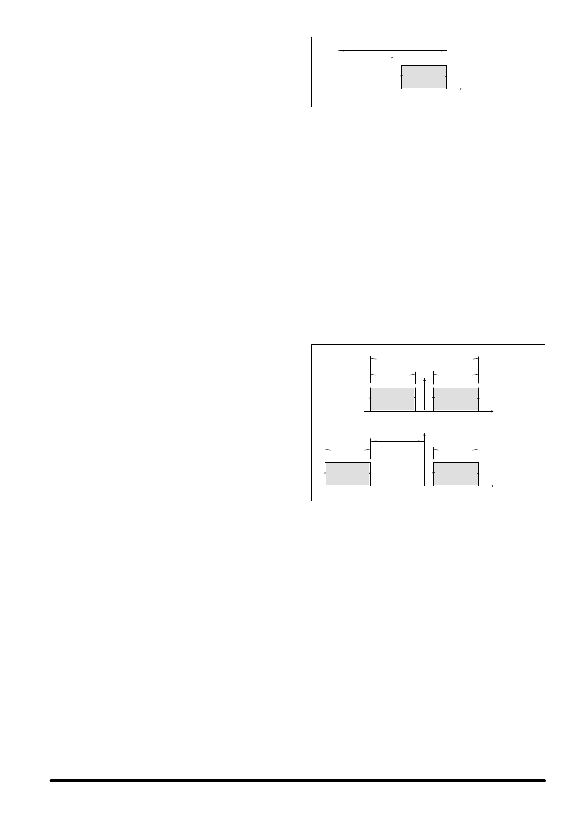
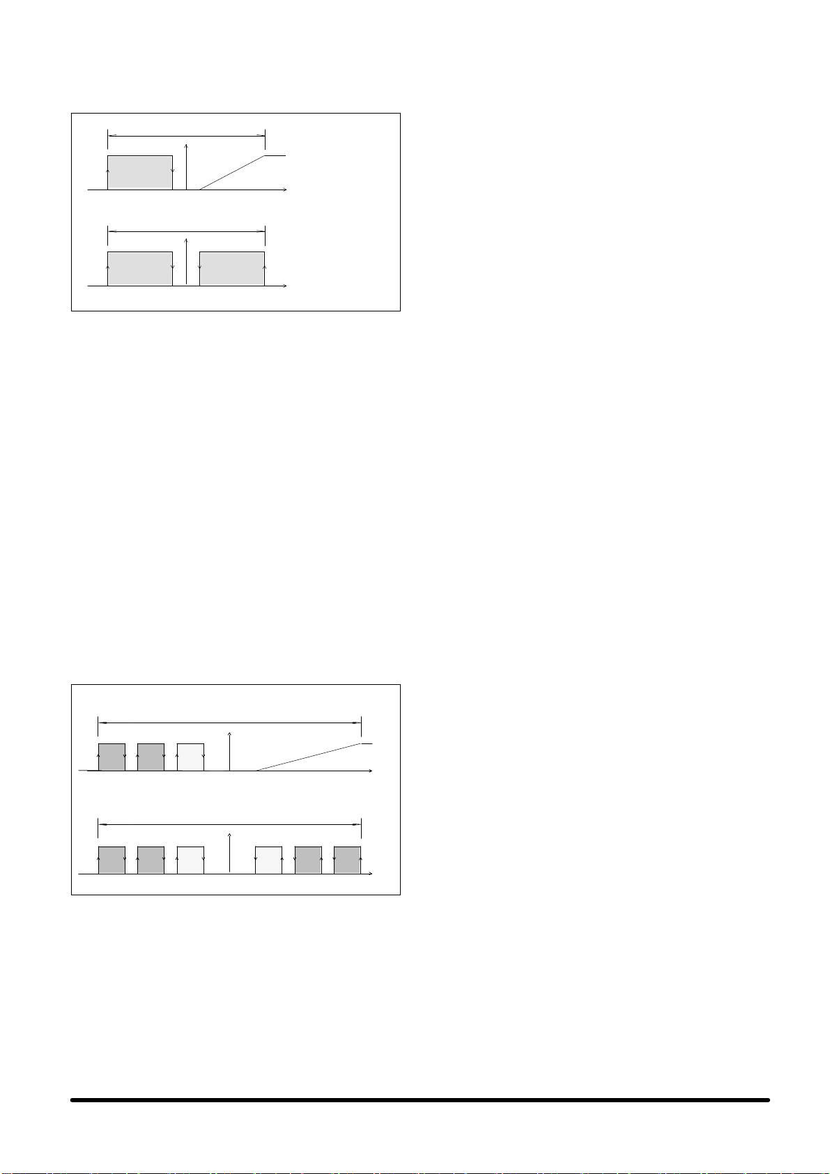
1.9 --- Service area
The unit must be provided with a suitable Service Area, as
fol-lows (see Fig. 5):
All ordinary maintenance can be performed from the
front.
Avoid possible obstacles hindering the air flows on the unit
outer side.
2 --- Mounting
For a correct installation proceed as follows:
Apply an insulating anti---vibration rubber between the unit
and the wall (see Fig. 9).
Before installing the unit open the integrated ducts for
the air distribution (fins) in the openings of the rear panel,
as in-dicated in the following points (1) and (2) and in
Fig. 10.
12
Secure the unit to the wall with 5+5 fasteners, flat---
head type with washer and nut on the indoor side (see
from Fig. 1 to Fig. 4). Hallow wall anchors or lag bolts
are suit-able as dictated by the wall constructions.
Seal the external boundary of the unit as preference
(see Fig. 9).
Caution: The units are designed to keep the room to be
conditioned as plenum, to prevent external dirt and
con-taminating agents from entering.
Plenum may reach high values in very sealed sites or if
the filters are not correctly serviced. In this way, doors and
win-dows are less functional and the unit efficiency is
de-