Vertiv VRC100 Series Installation and maintenance instructions

Vertiv™ VRC
VRC100 Series Self-contained Rack Cooler
Installer/User Guide
0.9 to 3.5 kW, 60Hz

Vertiv™ | VRC Installer/User Guide
Technical Support Site
If you encounter any installation or operational issues with your product, check the pertinent
section of this manual to see if the issue can be resolved by following outlined procedures.
Visit https://www.VertivCo.com/en-us/support/ for additional assistance.
The information contained in this document is subject to change
without notice and may not be suitable for all applications. While
every precaution has been taken to ensure the accuracy and
completeness of this document, Vertiv assumes no responsibility
and disclaims all liability for damages resulting from use of this
information or for any errors or omissions. Refer to other local
practices or building codes as applicable for the correct methods,
tools, and materials to be used in performing procedures not
specifically described in this document.
The products covered by this instruction manual are manufactured
and/or sold by Vertiv. This document is the property of Vertiv and
contains confidential and proprietary information owned by Vertiv.
Any copying, use or disclosure of it without the written permission
of Vertiv is strictly prohibited.
Names of companies and products are trademarks or registered
trademarks of the respective companies. Any questions regarding
usage of trademark names should be directed to the original
manufacturer.

TABLE OF CONTENTS
Safety Precautions 1
1 Vertiv™ VRC 3
1.1 Model Nomenclature 5
1.2 Specifications 5
1.2.1 Cooling Capacity 6
2 Equipment Inspection and Handling 7
2.1 Handling the Packaged Unit 8
2.1.1 Storing the Packaged Unit 9
2.2 Unpacking the Unit 9
3 Pre-installation Preparation 11
3.1 Cabinet and Room Requirements 11
3.2 Environmental Requirements 11
3.3 Clearance Requirements 12
3.4 Mounting, Ducting, Drain and Electrical-connection Considerations 12
4 Installation 13
4.1 Mounting the Unit in the Cabinet 13
4.2 Connecting Duct Work 15
4.3 Connecting the Condensate-drain Piping 16
4.4 Connecting Supply Power 17
4.5 Monitoring and Display Connections 18
5 Using the Controller and Display 21
5.1 Display Screens 21
5.1.1 Normal Screen 22
5.1.2 Entering Password and Menu 22
5.1.3 Alarm Screens 23
5.1.4 Temperature Settings Screen 25
5.1.5 System Status Screens 25
5.1.6 Help Screens 26
6 Regular and Preventive Maintenance 29
6.1 Cleaning and Replacing the Filters 29
7 Troubleshooting 33
Appendices 35
Appendix A: Checklist for Completed Installation 35
Appendix B: Preventive Maintenance Checklist 37
Vertiv | VRC Installer/User Guide | iii

Vertiv | VRC Installer/User Guide | iv

SAFETY PRECAUTIONS
IMPORTANT! This manual contains important safety instructions that must be followed during the
installation and maintenance of Vertiv™ VRC. Read this manual thoroughly and the safety and
regulatory information, available at https://www.vertivco.com/ComplianceRegulatoryInfo, before
attempting to install, service, or operate this unit.
Retain this manual for the entire service life of the unit.
Only qualified personnel should move, install or service this equipment.
Adhere to all warnings, cautions, notices and installation, operating and safety instructions on the unit
and in this manual. Follow all installation, operation and maintenance instructions and all applicable
national and local building, electrical and plumbing codes.
The VRC must be used exclusively for the purpose for which it is intended. The manufacturer takes no
liability for incorrect use or a modification to the unit.
Before handling, installing, or operating the system, read carefully the warning and caution notices that
accompany the procedures. Also, pay attention to the warning labels on the unit and its components.
1

Vertiv™ | VRC Installer/User Guide
2
This page intentionally left blank

1 VERTIV™ VRC
The VRC is a compact, integrated, rack-mounted cooling unit for use in a 19-in. EIA server rack.
Specifically designed for the cooling demand of the equipment mounted inside the rack, the VRC features
high reliability, high sensible-heat ratio and high air flow.
Figure 1.1 VRC Rack-mounted Cooling Unit
Item Description
1 Front view of VRC
2 Rear view of VRC
Installed at the bottom of the cabinet, the VRC provides air flow as shown in Figure 1.2 on the next page.
Hot return air enters from the rear of the cabinet, and conditioned cold air is supplied at the front of the
unit directly in front of the rack-mounted equipment..
Cooling capacity varies from 30% to 100%, approximately 0.9kW to 3.5kW to accommodate partial or
variable cooling loads.
1 Vertiv™ VRC 3

Figure 1.2 Air flow of the rack-mounted VRC indoor unit
Item Description
1 Space inside cabinet
2 Front of VRC
3 Rear of VRC
4 Heat-rejection air out
5 Hot air from cabinet in
6 Cool air from VRC out
Vertiv™ | VRC Installer/User Guide
4

1.1 Model Nomenclature
Table 1.2 below, describes each digit of the model number.
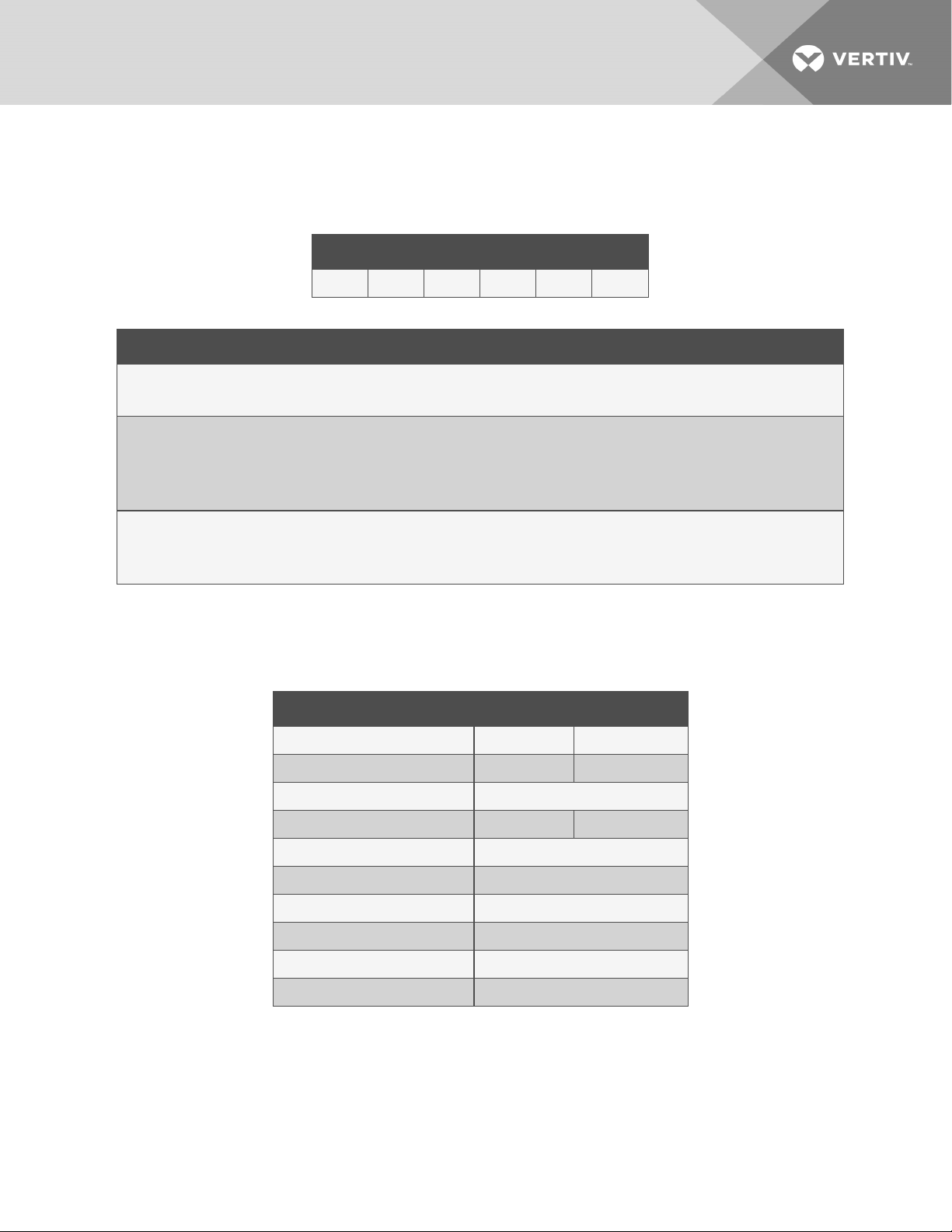
1 2 3 4 5 6
V R C 1 0 0
Table 1.1 VRC Model-number Example
Digit and Description
Digits 1, 2, 3 = Base unit
•VRC = Vertiv™ Rack Cooler
Digit 4 = System type
•1 = Self-contained cooling module
•2 = Split-system indoor cooling module
•3 = Split-system heat-rejection module
Digits 5, 6 = Power supply
•00 = 120V / 1ph / 60Hz
•01 = 208/230V / 1 ph / 60 Hz
Table 1.2 Model-number Digit Definitions
1.2 Specifications
Table 1.3 below, lists the mechanical and electrical specifications of the VRC by model.
Model: VRC100 VRC101
Cooling capacity, kW 0.9 to 3.3 0.9 to 3.3
Air volume, CFM (CMH) 450 (770) 465 (790)
Unit dimensions W xDx h, in.(mm) 17.4x38.5x17.28 (442x978x439)
Voltage, VAC L+N+G , 120 L1+L2+G, 208/230
Frequency, Hz 60
Color EG7021 (black)
System-protection grade IP20
Unit weight, lb (kg) 143.4 (65)
Shipping weight, lb (kg) 218.3 (99)
Noise level <66dB(A)
Table 1.3 Specifications by Model Number
1 Vertiv™ VRC 5

1.2.1 Cooling Capacity
Table 1.4 below, lists the net-sensible cooling capacity for various evaporator and condenser-air inlet
temperatures.
Condenser Air temperature, °F
85 95 104
Evaporator Air Temperature
into unit, °F
85 3.2 2.8 2.4
95 3.7 3.4 3.0
104 4.0 3.9 3.2
Table 1.4 Net Sensible (IT) Cooling Capacity, kW
NOTE: The addition of heat-rejection duct work may reduce cooling capacity.
Vertiv™ | VRC Installer/User Guide
6

2 EQUIPMENT INSPECTION AND HANDLING
Safety Precautions
WARNING! Risk of handling heavy unit and component parts. Can cause injury and equipment
damage. Use OSHA-recommended safe lifting techniques and/or lifting equipment rated for the
weight of the unit. Unit weights are specified in Table 1.3 on page5.
WARNING! Risk of improper moving. Can cause equipment damage, injury or death. Use only
lifting equipment that is rated for the unit weight by an OSHA-certified rating organization. The
center of gravity varies depending on the unit size.
CAUTION: Risk of contact with sharp edges, splinters, and exposed fasteners. Can causeinjury.
Only properly trained and qualified personnel wearing appropriate, OSHA-approved PPEshould
attempt to move, lift, remove packaging from or prepare the unit for installation.
NOTICE
Risk of damage from forklift. Can cause unit damage. Keep tines of the forklift level and at a
height suitable to fit below the skid and/or unit to prevent exterior and/or underside damage.
NOTICE
Risk of improper storage. Keep the unit upright, indoors and protected from dampness,
freezing temperatures and contact damage.
Upon arrival of the unit and before unpacking:
•Verify that the labeled equipment matches the bill of lading.
•Carefully inspect all items for visible or concealed damage.
•Report damage immediately to the carrier and file a damage claim with a copy sent to Vertiv™
or to your sales representative.
Equipment Recommended for Handling the Packaged Unit:
•Pallet jack or forklift
•Utility knife
2 Equipment Inspection and Handling 7

2.1 Handling the Packaged Unit
Transport the packaged unit with a fork lift or pallet jack. See Table 1.3 on page5, for the
packaged/shipping weight for your model. Figure 2.1 below, shows the dimensions of the packaged unit.
When using the fork lift or pallet jack, observe the following:
•Make sure that the lift/jack has adjustable fork arms, and the arms are spread to the widest
allowable distance to still fit under this pallet.
•Make sure that the fork arm length is suitable for the length of the pallet.
•When moving the packaged unit, align the fork arms with the unit center of gravity and do not
tilt the unit more than 20 degrees in any direction to prevent the unit from falling over.
•Place the unit as close as possible to the final installation location on a firm, level surface
Figure 2.1 Packaged-unit Dimensions
Vertiv™ | VRC Installer/User Guide
8

2.1.1 Storing the Packaged Unit
Store the unit in the original packaging in an area protected from excessive dirt, debris, and contact
damage until final installation. Observe the following requirements and the conditions listed in Table 2.1
below.
•Do not store the unit outdoors.
•Make sure that the unit stands upright.
NOTE: If the total shipment and storage time exceeds 6 months, the unit requires re-calibration for
proper performance.
Condition Requirement
Ambient temperature: –40to158°F (–40to70°C)
Ambient humidity: less than 95% relative humidity (103°F)
Table 2.1 Storage Conditions
2.2 Unpacking the Unit
All material used to package this unit is recyclable. Please save for future use or dispose of the material
appropriately.
1. Use a utility knife to cut the packing strip from the box.
2. Remove the cardboard box cover, sides, and supports, then remove the paper corners and
corner cushions.
NOTE: You will lift the unit from the wooden pallet when installing in the rack. Leave the pallet in place
until then.
2 Equipment Inspection and Handling 9

Vertiv™ | VRC Installer/User Guide
10
This page intentionally left blank

3 PRE-INSTALLATION PREPARATION
NOTE: Before installing unit, determine whether any building alterations are required to run piping,
wiring and duct work. Follow the figures, specifications, and listed requirements for proper clearances.
Proper preparation of the installation location and consideration of the installation environment optimizes
the performance of your VRC.
3.1 Cabinet and Room Requirements
To ensure the proper operation of the VRC, you must install the unit in a sealed cabinet in a room that
meets the following requirements:
•The cabinet must be moisture proof and free from air leaks that could destabilize the
temperature gradient.
•The cabinet must have appropriate thermal insulation and a sealed, moisture-proof layer.
•Minimize the amount of outdoor air entering the equipment room to prevent an unnecessary
load increase. We recommend keeping the leak rate of outdoor air below 5% of the total indoor
airflow.
•All room doors and windows should be closed properly to avoid infiltration of outside into the
room.
•Consider the weight-bearing capacity of the room floor because the weight of the system will
increase as equipment is added to the cabinet.
•Do not install the unit outdoors.
3.2 Environmental Requirements
Observe the following requirements and the operating conditions listed in Table 3.1 below, when
planning installation.
•Keep the unit away from flames or any heat source.
•Do not install in a location where the unit is exposed to direct sunlight.
•Do not install where the unit is exposed to corrosive gas or organic solvents.
Condition Requirement
Ambient temperature:
Indoor 64.4 to 104°F (18°C to 40°C)
Heat-rejection 32 to 104°F (0°to40°C)
Ambient humidity: less than 90% relative humidity
Altitude: less than 3,280 ft (100m). Derating is required when the altitude exceeds 3,280 ft (1000m)
Table 3.1 Operating Conditions
NOTE: Requirements for storage conditions are detailed in Storing the Packaged Unit on page9.
3 Pre-installation Preparation 11

3.3 Clearance Requirements
For installation and for maintenance access, the distance from the front door of the cabinet to a wall or
other obstacles must be greater than the length of the unit. You must be able to pull the unit completely
out for proper maintenance access. See Table 1.3 on page5, for the length or your VRC model.
The minimum clearance required for opening the front and rear doors to access the installed VRC is
shown in Figure 3.1 below.
Figure 3.1 Minimum Clearance for Installed Unit
3.4 Mounting, Ducting, Drain and Electrical-connection Considerations
This section provides an overview of the installation requirements for consideration before installing the
system. Detailed equipment and safety requirements are also included in the specific installation sections.
•The VRC is designed to provide cooling air to equipment above it in the cabinet. We
recommended installing the unit in the lowest section of the cabinet.
•The condensate-drain connection for drain piping is 1/2-in. Male NPT.
•If connecting heat-rejection duct work, fabricate and install duct work in accordance with local
codes.
•Electrical service must conform to national and local electrical codes. See Table 1.3 on page5,
for the electrical requirements for your VRC model.
Vertiv™ | VRC Installer/User Guide
12

4 INSTALLATION
WARNING! Arc flash and electric shock hazard. Open all local and remote electric power-supply
disconnect switches, verify with a voltmeter that power is Off and wear appropriate,
OSHA-approved personal protective equipment (PPE) per NFPA 70E before working with the
unit. Failure to comply can cause serious injury or death. Before proceeding with installation,
read all instructions, verify that all the parts are included and check the nameplate to be sure
the voltage matches available utility power. The unit controller does not isolate power from the
unit, even in the “Unit Off” mode. Some internal components require and receive power even
during the “Unit Off” mode of the controller.
WARNING! Risk of handling heavy unit and component parts. Can cause injury and equipment
damage. Use OSHA-recommended safe lifting techniques and/or lifting equipment rated for the
weight of the unit. Unit weights are specified in Table 1.3 on page5.
CAUTION: Risk of contact with sharp edges, splinters, and exposed fasteners. Can causeinjury.
Only properly trained and qualified personnel wearing appropriate, OSHA-approved PPEshould
attempt to move, lift, remove packaging from or prepare the unit for installation.
4.1 Mounting the Unit in the Cabinet
The unit is secured to the cabinet rails with mounting brackets shown in Figure 4.1 on the next page.
Each bracket has four 0.27-in. (7-mm) slots spaced 5.5in. (133.3mm) apart for attachment to the EIA rail.
1. Remove brackets 1 and 4 from the unit, set aside the fasteners for re-attachement.
2. At the front of the cabinet, slide the back of the unit into the cabinet until brackets 1 and 3 are
flush against the rack rails, see Figure 4.2 on page15.
3. Re-attach brackets 1 and 4 to the rear of the unit using the removed fasteners, then secure all
four brackets to the rack rails using the provided M6 panel screws and floating nuts.
4 Installation 13

Figure 4.1 Mounting Brackets
Item Description
1 Bracket 1
2 Bracket 2
3 Bracket 3
4 Bracket 4
5 Slots for fasteners
6 Rear of VRC
7 Front of VRC
Vertiv™ | VRC Installer/User Guide
14

Figure 4.2 Installing and Securing the Unit in the Rack
Item Description
1 Slide the unit into the rack.
2 Secure the brackets.
3 Unit installed.
4.2 Connecting Duct Work
If the condenser hot air discharged by the VRC must be removed from the immediate area or room, you
may connect ducting to the air outlet on the rear of the unit. If the duct work removes hot air from the
room or into a dropped ceiling, make provisions to bring make-up air into the room. Install duct work in
accordance with local codes.
If your system includes the optional duct-work kit, follow the instructions included with the kit to install
and connect the duct work.
NOTE: Ducting is optional, and the duct work shown in Figure 4.3 on the next page, is and example of
the installed duct.
4 Installation 15

Figure 4.3 Duct Connection Example
4.3 Connecting the Condensate-drain Piping
NOTICE
Risk of clogged or leaking drain lines. Can cause equipment and building damage. This unit
requires a water drain connection. Drain lines must be inspected at start-up and periodically,
and maintenance must be performed to ensure that drain water runs freely through the drain
system and that lines are clear and free of obstructions and in good condition with no visible
sign of damage or leaks. Improper installation, application and service practices can result in
water leakage from the unit. Water leakage can result in catastrophic and expensive building
and equipment damage and loss of critical equipment. Do not locate unit directly above any
equipment that could sustain water damage. We recommend installing a monitored fluid-
detection system to immediately discover and report condensate drain-line leaks.
The VRC includes a 1/2-in. Male NPT connector for the condensate drain. Observe the following
requirements when installing and routing the drain line:
•The drain line must be sized for 1 gpm (3.8 l/m) flow.
•The drain line must comply with all applicable codes.
•The drain line must be located so it will not be exposed to freezing temperatures.
•Do not externally-trap the drain line. The unit already has an internal trap on the condensate
drain line.
•The drain line must slope continuously downwards away from the unit.
•If the drain connection is below the gravity-fed drain line, an optional condensate-drain pump
kit is required, and the pump inlet must be below the unit's condensate-drain outlet when
installed. Contact your Vertiv™ representative for additional information.
Figure 4.4 on the facing page, shows the drain-line connection on the unit.
Vertiv™ | VRC Installer/User Guide
16
This manual suits for next models
1
Table of contents
Other Vertiv Freezer manuals

Vertiv
Vertiv VRC1 Series User manual

Vertiv
Vertiv Liebert HPM User manual

Vertiv
Vertiv Liebert HPW Series User manual

Vertiv
Vertiv VRC1 Series User manual

Vertiv
Vertiv Liebert DSE060 Installation and maintenance instructions

Vertiv
Vertiv Liebert XDP Series User manual

Vertiv
Vertiv Liebert XDC User manual

Vertiv
Vertiv Liebert DSE User manual