VEXILAR 107 PRO User manual

CONTENTS
General Description 2
Specifications 4
Unit Installation 5
Mounting the Sensor Box 6
Assembling the Transducer 6
Attaching the Sensor 7
Mounting the Transducer 8
Operation 12
Menu Functions 15
Typical Indications 22
Maintenance 26
Trouble Shooting 27
Other Products 28
Service and Support 31
Founded in 1965, Vexilar, Inc.
has a long history of bringing revolutionary technology to
the sport fishing industry. Just some of the Vexilar firsts
include: the first liquid crystal display, the first fish alarm,
the first three color display, and the first CRT and straight
line paper graphs, for the sport fisherman.
1
107 Pro Operation Manual

GENERAL DESCRIPTION
The 107 Pro incorporates an extremely high quality
sonar circuit with an easy to understand interface. The unit
is designed to be effective and easy to use. All the main
functions are only one button away. Range and Gain con-
trols are selectable as fully automatic or easily controlled
manual modes independent of each other. Internal battery
backup saves all selections upon power off.
The output frequency of 107 KHz is much lower than
most depthfinders of today. This is designed to give more
output power and a greater area of coverage. The 107 Pro
can truly "arc" fish and does not need to use artificial fish
symbols.
The 107 Pro incorporates Clean Line circuitry that can
"clean out" the harder targets. The bottom, rocks, and dense
weeds are made transparent so fish are more visible near
them. On a hard rock or gravel bottom, fish on the edge of
the cone angle can actually be seen within the bottom sig-
nal. And with a 38˚cone angle, you can cover allot of area.
There are three Zoom Zones which let you hone in on
the area you want to see best. You can zoom just the top
half, middle, or bottom half of the display. These features
are easily activated by a single press of a button. Switching
back and fourth is quick and easy.
Speed and Temperature sensors are included. Two dis-
2

play modes provide a standard graphic view mode or a
digital mode which includes a temperature graph. There
is also a trip log feature to help keep track of the distance
you have traveled.
There are more features, including programmable bot-
tom alarm, fish alarm, a high speed vertical mode, and a
Clean Echo feature to eliminate interference
All told, the 107 Pro is a powerful tool for visualizing
structure and fish, in almost all situations. Quality con-
struction and superior product support. Long Vexilar tra-
ditions that go with this unit, and everything else we pro-
duce.
3

4
• Operating Voltage:
• Current Draw:
• Power Output:
• Frequency:
• Resolution:
• Sounding Rate:
• Display Size:
• Dimensions:
• Weight:
8.5 - 16 Volts (12 Volts Nominal)
200mA (400 mA w/Backlight On)
1200 Watts (Peak to Peak)
107 Khz
64 x 128 Pixels
700/Min.
2" x 4 3/4"
7.1"H x 9.5"W x 1.9"D
1.1 Lbs. (Unit Only)
SPECIFICATIONS
• Depth Ranges:
0-5', 0-10', 0-15', 0-20', 0-30', 0-40', 0-60', 0-80', 0-120',
0-160', 0-240', 0-320', and 0-480'.
Figure 3

INSTALLATION
You will need to find a place to mount the 107 Pro that
will make it easy to view and reach. You must provide the
unit with power and mount the transducer and sensor
assembly in an effective location.
MOUNTING THE UNIT
Find a convenient place to mount the unit. This may
include a boat seat, deck, dash, or a portable case. Make
sure that there is plenty of room for the unit to tilt freely
without the cables binding or stretching behind the unit.
Once you have found the spot, remove the unit from the
gimbal bracket. Securely attach the bracket to the mount-
ing surface. The screws provided are 5/8" long and are for
wood/carpet or dash mounting applications. An optional
removable swivel bracket is available.
CONNECTING POWER
Plug the 3 pin connector into the back of the unit. Find
the closest source of 12 volts and route the cord to it. Keep
the cord away from sharp metal edges and avoid tight
places where the cord may get crushed. Connect the white
wire to positive and the black wire to negative. If the cord
provided is not long enough, more can be added. Use 18
gauge wire minimum. Install the included 1 amp in-line
fuse, placed in the positive line, as close to the power source
as possible, to protect against shorts in the wiring.
5

MOUNTING THE SENSOR BOX
The sensor box needs to be located within three feet of
the main unit. It is recommended that it be fastened to a
sturdy surface. You can mount it, using the screws pro-
vided, to a flat surface or you can simply tie it to a frame
or wire harness, using cable ties which are not provided.
The sensor box is weather proof, but be sure to keep it out
of an area that may fill with water.
ASSEMBLING THE TRANSDUCER
Locate the transducer, and bracket hardware. This
includes;
1 Transducer
2 Angle Brackets
4 Bracket Screws
4 Washers
4 Nuts
4 Mounting Screws
Attach the bracket to the
transducer as shown in Figure 4. The flanges of the brack-
et normally point outward, away from the transducer. If
mounting space is tight, you can reverse the angle brack-
ets and face the flanges inward.
6
Figure 4

ATTACHING THE SENSOR ASSEMBLY
The speed and tempera-
ture sensor assembly attach-
es to the transducer as
shown. Pinch, or squeeze,
together the tabs at the top
of the sensor and slide the
assembly down into the
tracks on the back of the
transducer. Push it down
until it stops, and then, push
the tabs back outward until
the catches snap into the
holes on the transducer.
ALTERNATE SENSOR MOUNTING
If you plan on mounting the transducer inside the hull
of the boat or on an electric trolling
motor (described on page 11) you
will need to use the provided sen-
sor mounting bracket, instead of the
transducer to mount the sensor.
CAUTION - It is a good idea to restrain the speed wheel
from spinning freely while trailering the boat. Damage may
result because there is no water to lubricate the wheel bear-
ings. A rubber band works good for this.
7
Figure 5
Figure 6

MOUNTING THE TRANSDUCER
The 107 Pro transducer is designed to be mounted on
the transom of the boat. The shape will allow a clear depth
reading at any boat speed, if properly installed.
Locate a spot similar to the one in figure 7. Keep in mind
that you need clear water flow across the face of the trans-
ducer to insure a clear reading at all speeds. Stay away from
rivets, ribs, or strakes that would be just in front of the trans-
ducer. They will disturb the water and scramble the read-
ing. Attach the mounting bracket to the transducer and
hold it up to the boat where you are planning to mount it
(see figure 7).
Mark the four holes on the transom, or mounting plate,
8
Figure 7

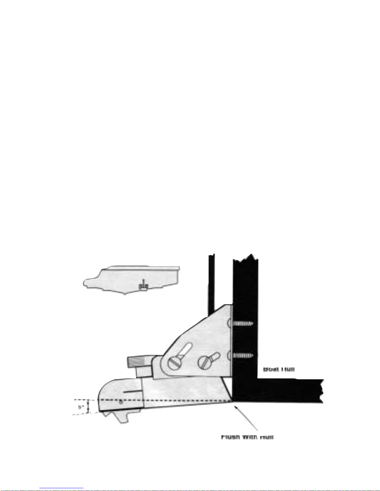
so that when the bottom of the transducer is flush with the
bottom of the boat the holes are located at the bottom of
the bracket slots. This gives you room to "fine tune" the
position of the transducer and optimize your reading after
you've put the boat back in the water. Drill out the holes
and install the transducer bracket assembly. Tighten the
screws down securely. Be sure to seal any holes drilled into
the transom with silicone to prevent water from leaking
into the boat.
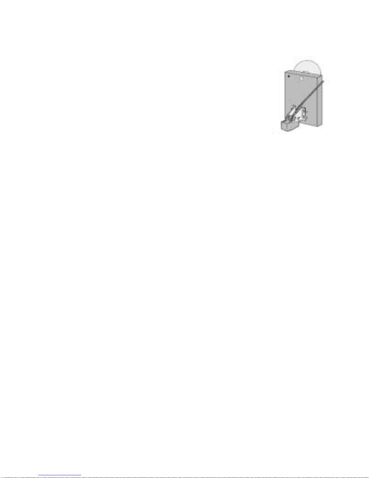
Route the transducer cord up to the unit taking the
same. care as you did when you routed the power cord.
Make sure that the cord is restrained and not allowed to
flop around in the wind. This can cause stress on the wire
inside the cable, and possible breakage. Plug the transducer
connector into the back of the unit and screw the retaining
ring down tight.
After you have put the boat back in the water confirm
that you can maintain a bottom reading at all boat speeds.
If not, loosen the bracket screws and tilt the transducer
some more. Keep the front edge flush with the boat, but
drop the back edge down a little more. If changing this
angle several times does not clear up the reading, loosen
the mounting screws and slide the transducer down, slight-
ly. Repeat these adjustments until you get a clear reading.
Finally, make sure that all mounting screws are tight.
Fill any gap between the transducer and the hull with
silicone to prevent a rooster tail from shooting up behind
the boat.
9

PORTABLE MOUNTING
An optional suction cup bracket can be
used to temporarily attach a transducer to the
transom or side of the boat. The cups should
be placed in a location where they will not be
torn off when the boat goes high speed, but
still just low enough to maintain the high speed reading.
The optional BK0044 suction cup mounting plate works
well for this application.
An arm assembly that clamps to the transom or side of
the boat can also be used to hold the transducer. Simply
attach the transducer to the end of the arm using cable ties
or tape. If the arm is constructed of metal tubing insulate
the transducer from the arm by wrapping electrical tape
around the arm. This prevents "ringing" which can be dis-
played as noise near the surface.
IN-HULL MOUNTING
Finding the best location for the transducer before
mounting is critical. Choose a flat smooth spot near the
center of the bilge and near the back of the boat. It is a good
idea to make a "test run" before you permanently install
the transducer. This makes sure that you can, indeed, get
a reading through your hull, and when the boat is on plane.
Put about a half inch of water in the bilge and hold the
transducer in the intended location. Move the transducer
around until you get the best reading. Mark the spot.
To install the transducer, clean the spot of mud and oil.
10

Using an epoxy or silicone
glue, make a puddle about
the same diameter as the
transducer on the hull. Place
the transducer in the glue.
Press it down firmly, gently
twisting it back and forth,
making sure that there are no
air bubbles in the glue
between the transducer and
the hull. Let the glue dry completely before turning the unit
on.
TROLLING MOTOR MOUNTING
Use two hose clamps or large cable ties (not included)
to attach the transducer to an electric trolling motor. Using
the slots in the transducer, run the ties through them and
around the motors lower unit. Locate the transducer on the
bottom of the lower unit as in figure 10. Run the cable up
the shaft using smaller cable ties to hold it in position. Make
sure that the cable will not be
damaged by the movement of
the trolling motor. Plug the trans-
ducer connector into the back of
the unit and screw the retaining
ring down tight.
11
Figure 10

OPERATION
Figure 11 shows the main controls of the
107 Pro.
POWER - OFF / ON
Turns the 107 Pro OFF and ON. Press the
ON button to turn the unit on. You will hear
a short beep when the unit powers on. Press
the OFF button to turn the unit off. All fea-
ture settings will be stored in memory so that
when you turn the unit on again, it will oper-
ate the same way as it did when you last
used it.
MENU
Pressing the menu button enters the first menu page.
Pressing this button while in a menu page moves you to
the next menu page. Menu items will be explained in the
next section.
FREEZE / RESUME
During normal operation, press the FREEZE / RESUME
button to stop the movement of the display. Press the but-
ton again to resume back to normal operation.
While in any menu page, press the FREEZE / RESUME
button to return to normal operation.
12
Figure 11

GAIN CONTROL
The 107 Pro comes selected from the factory to run in
automatic gain mode. The unit will monitor the conditions
and adjust the gain, or sensitivity, to an optimum level. If
you wish, you can over ride this feature in the MENU set-
tings and adjust the gain manually. Then, you will press
the DEC button to decrease the gain level. Press the INC
button to increase the gain level.
RANGE CONTROL
The 107 Pro comes selected from the factory to run in
automatic range mode. The unit will monitor the depth
and change the range for you when the depth changes. You
can override this feature in the MENU setting and change
the range manually. Press the SHALLOW button to change
the range to the next shallower range. Press the DEEP but-
ton to change the range to the next deeper range.
SWEEP
SWEEP controls how fast the display moves across the
screen. This speed should, roughly, match the speed of the
boat. Press the SLOW button to slow down the display one
step. Press the FAST button to speed up the display one
step.
13

DISPLAY
Selects between two different display modes. Press the
A button to view the standard graphical view. Press the B
button to view the "windowed" view. This view provides
depth, temperature, speed, and log information in large,
easy to read, numbers. It also displays a temperature graph
and an A-Mode depth display.A-mode is an instantanious
vertical depth display, described in the next section.
ZOOM
The 107 Pro has three different Zoom Zones. You can
select to view only the top half, middle half, or bottom half
of the depth. Using a Zoom Zone, effectively, doubles the
display resolution, making things appear twice as large.
The Zoom Zone feature works in both standard and A-
Mode views.
Press the TOP button to view only the top half of the
depth. Press the MIDDLE button to view only the middle
half of the depth. Press the BOTTOM button to view only
the bottom half of the depth. Press the NORMAL button
return to the standard display mode.
14

MENU FUNCTIONS
Press the MENU button to enter the first menu page.
Press the MENU button again to enter the second menu
page.
AUTO GAIN
Press MENU, then, the 1, or DEC, button to enter the
AUTO GAIN submenu. This feature has three available
settings.
Press the 1 button to turn off the automatic gain feature.
You now must change the gain level manually using the
GAIN buttons on the front of the unit. Press the 2, or SHAL-
LOW button to turn the automatic gain control on to the
High setting. Press the 3, or SLOW, button to select the Low
automatic gain setting. Press the FREEZE / RESUME but-
ton to return to the normal view.
The High setting will keep the gain level higher than
the Low setting. The default setting is High, but better
results in shallow or weedy waters may be possible with
the Low setting.
AUTO RANGE
Press MENU, then the 2, or SHALLOW, button to enter
the Auto Range submenu. Press the 1 button to turn the
auto range feature off. Press the 2 button to turn the fea-
ture on.
15

BOTTOM ALARM
Press MENU, then the 3, or SLOW, button to enter the
Bottom Alarm submenu. Press the 1 button turn this fea-
ture off, the default. Press the 2 button to turn this feature
on.There are two values to be entered in the alarm settings.
There are also several different ways in which the alarm
works, depending on the depth values you enter. The best
way to describe this feature is by example.
Example 1 - To set the alarm to sound whenever the
depth gets less than three feet, press the 4 button to enter
the upper alarm limit. Press the 0 button to enter the value
of zero. Press the SET button to enter this value. If you make
a mistake entering the value, press the CLR button and
then retry. Now, press the 5 button to set the lower alarm
limit. Press the 3 button, and then, the SET button to enter
the value of three. Finally, press FREEZE/RESUME
Example 2 - To set the alarm to sound whenever the
depth is between five and fifteen feet, press the 4 button to
enter the upper alarm limit. Press the 5 button to enter the
value of five. Press the SET button to enter this value. If
you make a mistake entering the value, press the CLR but-
ton and then retry. Now, press the 5 button to set the lower
alarm limit. Press the 1 button, and then, the 5 button.
Finally, press the SET button to enter the value of fifteen.
Then, press FREEZE/RESUME
16

Example 3 - To set the alarm to sound whenever the
depth gets less than five feet or more than fifteen feet, press
the 4 button to enter the upper alarm limit. Press the 1 but-
ton and then the 5 button to enter the value of fifteen. Press
the SET button to enter this value. If you make a mistake
entering the value, press the CLR button and then retry.
Now, press the 5 button to set the lower alarm limit. Press
the 5 button, and then, the SET button to enter the value of
five. Then, press FREEZE/RESUME.
Example 4 - To set the alarm to sound whenever the
depth gets more than fifteen feet, press the 4 button to enter
the upper alarm limit. Press the 1 button, and then, the 5
button to enter the value of fifteen. Press the SET button to
enter this value. If you make a mistake entering the value,
press the CLR button and then retry. Now, press the 5 but-
ton to set the lower alarm limit. Press the 0 button, and
then, the SET button to enter the value of zero. Then, press
FREEZE/RESUME.
FISH ALARM
Press MENU, then, the 4 button, to enter the Fish Alarm
submenu. There are two sensitivity settings for the Fish
Alarm. Press 2 to activate the alarm and set the sensitivity
to High or 3 to set it to Low sensitivity. When set to High,
the alarm will sound on all fish targets. When set to Low,
it will only sound on larger fish targets. Set the Upper and
Lower limits the same way as described in the Bottom
Alarm section. 17

LIGHT
To turn on the backlight, for night use, press the MENU
button, then, the 5 button to enter the Light submenu. Press
the 2 button to turn it on and the 1 button to turn it off.
CONTRAST
To adjust the liquid crystals display contrast, press
MENU, then, the 6 button to enter the Contrast adjustment
submenu. Press any numbered button between 1 and 8 to
adjust the Contrast. 1 will give the lightest setting and 8
will give the darkest setting.
TEMP
To turn the Temperature sensor on, press MENU, then,
the 7 button to enter the Temp submenu. Press the 2 but-
ton to turn it on and the 1 button to turn it off.
SPEED
To turn the Speed sensor on, press MENU, then, the 8
button to enter the Speed submenu. Press the 2 button to
turn it on and the 1 button to turn it off. If you find that
your reading is not correct you can correct it in this sub-
menu. Press the 3 through 9 buttons to correct the reading
as needed.
18

LOG
The Log is a feature that works with the Speed sensor
to keep track of total distance traveled. Press MENU, then,
the 9 button to enter the Log submenu. Press the 2 button
to turn it on and the 1 button to turn it off. The Log will
keep accumulating your distance traveled until you turn
it off. You can turn the Log back on to add more distance
or press the 3 button to clear the Log and start a new read-
ing.
SIMULATION
The 107 Pro has a built-in Simulator to help you learn
or demonstrate the functions of the unit. The Simulator is
a short program which simulates a real world situation. All
of the front panel controls and menu functions can be used
with the simulator.
Press the MENU button twice, then, the 1 button to enter
the Simulator submenu. To turn the simulator on, press the
2 button. To turn it off, press the 1 button.
SYSTEM RESET
Press the MENU button twice, then, the 2 button to enter
the system reset submenu. RESET returns all settings back
to the factory original settings. Press the 2 button to reset
the system. Use this feature to trouble shoot problems or
to get back to a "known" state . Caution - All settings,
including the Log value, will be erased.
19

CLEAN LINE
Clean Line is a feature which can help determine the
hardness of the bottom. Clean Line "cleans out" the target
signal on harder objects. A hard bottom will appear cleaned
out in the center. A soft bottom will be all black.
Press the MENU button twice, then, the 3 button to enter
the Clean Line submenu. There are two levels, High and
Low. Use High over softer bottom and Low over harder
bottom. Press the 2 button to activate the Clean Line fea-
ture on High. Press the 3 button for Low.
CLEAN ECHO
Clean Echo reduces interference from other depthfind-
ers running on the same frequency. Press the MENU but-
ton twice, then, the 4 button to enter the Clean Echo sub-
menu. To turn it on press the 2 button. To turn it off press
the 1 button.
A-MODE
A-Mode gives an instantaneous, vertical, representa-
tion of the depth below. It gives you the ability to recog-
nize bottom changes and targets before they scroll onto the
normal display.
To enter the A-Mode submenu, press the MENU but-
ton twice, then, the 5 button. To activate the feature press
the 2 button. To turn it off press the 1 button.
20
Table of contents
Other VEXILAR Sonar manuals
Popular Sonar manuals by other brands

Lowrance
Lowrance X71 Installation and operation instructions

Simrad
Simrad SX90 SW 1.3.6 - SOFTWARE RELEASE NOTE REV E release note

Garmin
Garmin Panoptix Livescope LVS12 installation instructions

Eagle
Eagle FISH I.D. AND PLUS installation instructions

Furuno
Furuno CH-270 Service manual

Lowrance
Lowrance LMS-150 GPS Installation and operation instructions

FarSounder
FarSounder FarSounder-500 Operation manual

Lowrance
Lowrance X-55 Installation and operation instructions

Humminbird
Humminbird ICE 35 Installation and operation manual

Furuno
Furuno FSV-24 installation manual

Furuno
Furuno FSV-85-MARK-2 installation manual

Interphase
Interphase Sonar Engine SE-200 installation instructions