VICE BOLD LIGHTING U50 User manual

WARNING:
THE SAFETY OF THIS FIXTURE IS GUARANTEED ONLY IF YOU COMPLY WITH THESE INSTRUCTIONS
BRACKETS INSTALLATION (EXTENDED BRACKET)
ON
OFF
MAKE SURE THE POWER
IS OFF DURING INSTALLATION
THE LOW SURFACE TEMPERATURE (40°C)
IMPOSE NO LIMITS ON INSTALLATION
40°C
USA - BOLD LIGHTING Atlanta, GA 30075 +1 (833) 265-3187
Lebanon P.O. Box. 11-0125 - Beirut +961 1 486311
USA Revision: 1 Apr 2019
Page 1/7
IP66
U50 LIGHTWAY OUTDOOR
Product Installation Guide
LUMINAIRE PARAMETERS
1
2
SIDE VIEW
TOP VIEW
7”(175mm)
22/3”(69mm)
2”(54mm)
SECTION
Locate the Bracket shown in Fig.1 in your packaging boxes.
Contractor to make sure supporting surface can bear the weight and load of products to be installed. Contractor to provide proper
backing or blocking behing non-weight bearing surfaces. Spacing of brackets to follow provided shop drawings.
Anchoring fasteners are to be provided by Contractor. Any anchoring device should be checked for compatibility with the mounting
surface type and its load bearing specifications.
Mounting Screws to be tightened until the bracket is entirely in contact with the mounting surface. DO NOT over-tighten fasteners if gaps
between the bracket and mounting surfaces are still showing due to surface un-eveness.
Fig.1
Fig.2
Make sure the brackets spacing are installed in a such way to
ensure between 3”and 8”from the endcap or the end of the
fixture.
For asymmetric optics make sure the luminaire is set with the correct
side towards the surface to be illuminated
We reserve the right to make technical changes without prior notice.

USA - BOLD LIGHTING Atlanta, GA 30075 +1 (833) 265-3187
Lebanon P.O. Box. 11-0125 - Beirut +961 1 486311
USA Revision: 1 Apr 2019
Page 2/7
U50 LIGHTWAY OUTDOOR
Product Installation Guide (Continued)
WARNING:
Fig.3
The U50 Lightway fixture has 2 sets of
2 groove lines, one on the bottom for
a bottom bracket installation and one
on the side for a wall mounting set-up
please use the required grooves
according to your mounting conditions
Clip in the bracket in the grooves by
inserting one side of the bracket lip in
the first groove and then rotating the
bracket to clip in the second bracket lip
in the second groove
The U50 Lightway Brackets have a lock screw that prevents
the bracket from getting loose. The Screw shown in red in
Fig.4 should be tightened until it applies a reasonnable
pressure on the inner side of the bracket. Do not over-tighten
the screw to prevent damage to the bracket.
Failure to tighten the lock screw on the brackets might
result in injury or death due to xtures getting loose and
falling out from their brackets
Fig.4
6” (155mm)
10” (256mm)
71/4” (183mm)
71/2”(192mm)
101/2” (266mm)
61/2” (167MM)
WALL MOUNTED
BOTTOM MOUNTED
160º
160º
We reserve the right to make technical changes without prior notice.

USA - BOLD LIGHTING Atlanta, GA 30075 +1 (833) 265-3187
Lebanon P.O. Box. 11-0125 - Beirut +961 1 486311
USA Revision: 1 Apr 2019
Page 3/7
U50 LIGHTWAY OUTDOOR
Product Installation Guide (Continued)
BRACKETS iNSTALLATION (SHORT SIDE BRACKET- FLOOR)
2
The U50 Lightway fixture has 2 sets of 2 groove lines, on the the side for a wall mounting set-up Please use the required grooves A
ccording to your mounting conditions
Clip in the bracket in the grooves by inserting one side of the bracket lip in the first groove and then rotating the bracket to clip in the
second bracket lip in the second groove
Install the bracket plates on the supporting
surface using adequate anchoring fasteners
for the load and surface material
SIDE MOUNTED BRACKET - FLOOR MOUNT
We reserve the right to make technical changes without prior notice.
SIDE VIEW
TOP VIEW
69
105
WARNING:
The U50 Lightway Brackets have a lock screw that prevents
the bracket from getting loose. The Screw shown in red in
Fig.4 should be tightened until it applies a reasonnable
pressure on the inner side of the bracket. Do not over-tighten
the screw to prevent damage to the bracket.
Failure to tighten the lock screw on the brackets might
result in injury or death due to xtures getting loose and
falling out from their brackets

USA - BOLD LIGHTING Atlanta, GA 30075 +1 (833) 265-3187
Lebanon P.O. Box. 11-0125 - Beirut +961 1 486311
USA Revision: 1 Apr 2019
Page 4/7
U50 LIGHTWAY OUTDOOR
Product Installation Guide (Continued)
BRACKETS iNSTALLATION (SHORT SIDE BRACKET- WALL)
2
The U50 Lightway fixture has 2 sets of 2 groove lines, on the the side for a wall mounting set-up Please use the required grooves
According to your mounting conditions
Clip in the bracket in the grooves by inserting one side of the bracket lip in the first groove and then rotating the bracket to clip in the
second bracket lip in the second groove
Install the bracket plates on the supporting
surface using adequate anchoring fasteners
for the load and surface material
SIDE MOUNTED BRACKET - WALL MOUNT
We reserve the right to make technical changes without prior notice.
SECTION VIEW
WARNING:
The U50 Lightway Brackets have a lock screw that prevents
the bracket from getting loose. The Screw shown in red in
Fig.4 should be tightened until it applies a reasonnable
pressure on the inner side of the bracket. Do not over-tighten
the screw to prevent damage to the bracket.
Failure to tighten the lock screw on the brackets might
result in injury or death due to xtures getting loose and
falling out from their brackets
2”
2 9/16”
TOP VIEW
2”
SIDE VIEW
2 9/16”

USA - BOLD LIGHTING Atlanta, GA 30075 +1 (833) 265-3187
Lebanon P.O. Box. 11-0125 - Beirut +961 1 486311
USA Revision: 1 Apr 2019
Page 5/7
U50 LIGHTWAY OUTDOOR
Product Installation Guide (Continued)
BRACKETS INSTALLATION (FIXED- BOTTOM)
2
The U50 Lightway fixture has 2 sets of 2 groove lines, on the the side for a wall mounting set-up Please use the required grooves
According to your mounting conditions
Clip in the bracket in the grooves by inserting one side of the bracket lip in the first groove and then rotating the bracket to clip in the
second bracket lip in the second groove
We reserve the right to make technical changes without prior notice.
Screw the brackets into the floor. Insert the male/female connector for through wiring.
A maximum of 2 luminaires of 24” with a P3 output can
be mounted on one remote driver.
Power In
Clip in the luminaires in place.
Use pins: Earth, N and 1
for power in connection.
Use pins: 2 and 3
for luminaires inter-connection.

ON
OFF
Shock hazard. Serious injury or death may occur. Turn Off power
before servicing or installing. Wire according to local and national
codes. This product shall be installed by a qualified electrician
Wiring Instructions
Refer to next page for wiring instructions. Follow carefully
wiring diagram for various dimming protocols.
Before beginning the wiring process, double check the type
of connection specified. T1 Type fixture only have an input, and
cannot be used for daisy chained fixtures. CONTINUOUS RUNS, Type
T2 fixtures have though wiring and are meant to be daisy chained.
3
USA - BOLD LIGHTING Atlanta, GA 30075 +1 (833) 265-3187
Lebanon P.O. Box. 11-0125 - Beirut +961 1 486311
USA Revision: 1 Apr 2019
Page 6/7
U50 LIGHTWAY OUTDOOR
Product Installation Guide (Continued)
N.B: All luminaires are labelled with “ IN ” and “ OUT ” labels. Installer should respect the below diagram.
All Luminaires are equipped with cables and relative connectors. Installer can shorten the cable respecting the connections
cable wiring order.
IN
Male
connector
Female
connector
Use Pins: (2 and 3)
OUT IN INOUT
DRIVER
LUMINAIRE LUMINAIRE LUMINAIRE
1- Line
N- Neutral
- Earth
Power In
LOW VOLTAGE Feed Cable
IN-OUT Jumper Cables
For Dimmable 0-10V and DALI fixtures refer to wiring instruction and wiring color coding on page 4.
Fig.5
Fig.7
Cables and Jumpers Installation
Connect the main feed cable to the first in run fixture.
Connect Intermediate fixtures together using the IN-OUT
jumper cables as per Fig.5. Leave enough cable length to
allow easy Connection of fixtures together.
Connect Feed-in Connector to Leader Feed-in Cable as per the
instructions provided on Page 4. Provide power and test
connections. See Wiring Details on Page 3 & 4 for reference.
Once the electrical connections have been tested, secure
conduits and couplers tightly.
Make sure sealing caps are installed on all opened connec-
tors.
Make sure no cables are pinched by a bracket or a
fixture during installation. Pinched or damaged
cables could result in serious injuries or death
We reserve the right to make technical changes without prior notice.

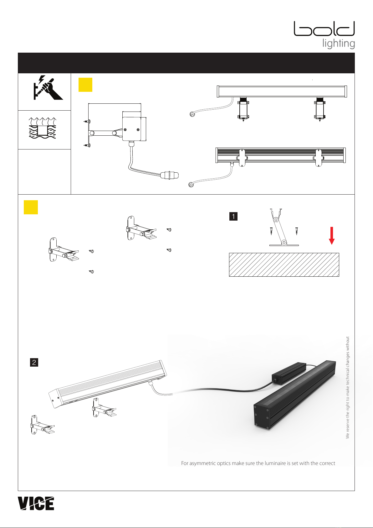
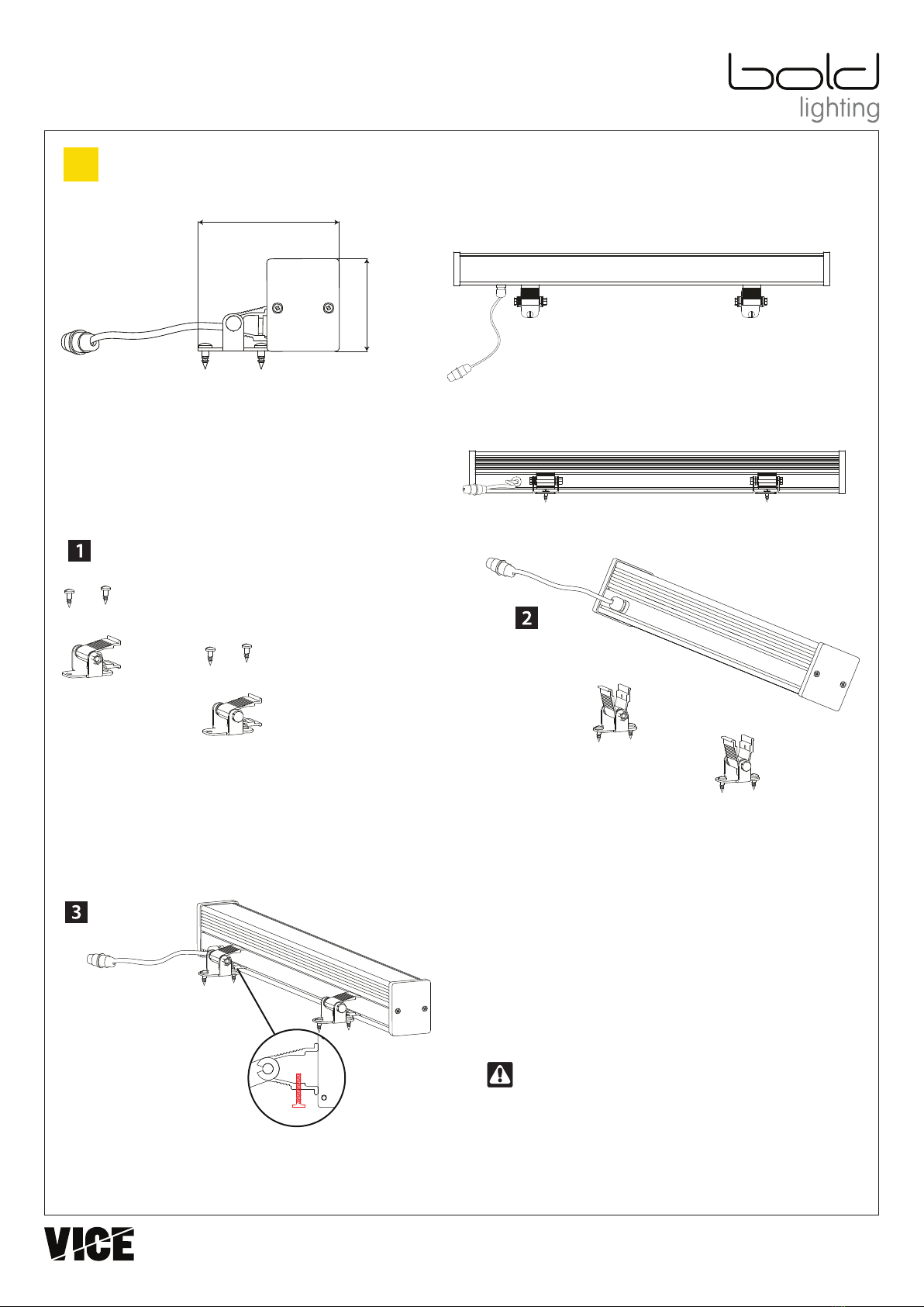
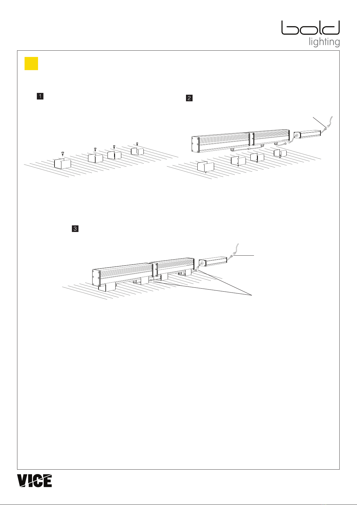
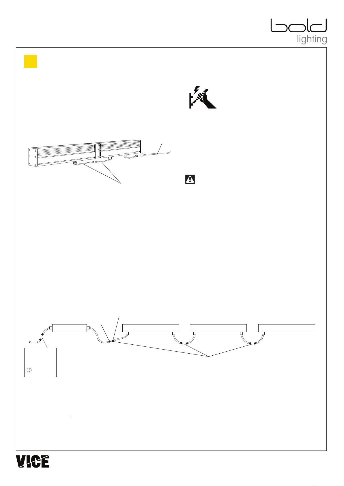
Wiring Instructions for continuous runs (Daisy Chained Fixtures)
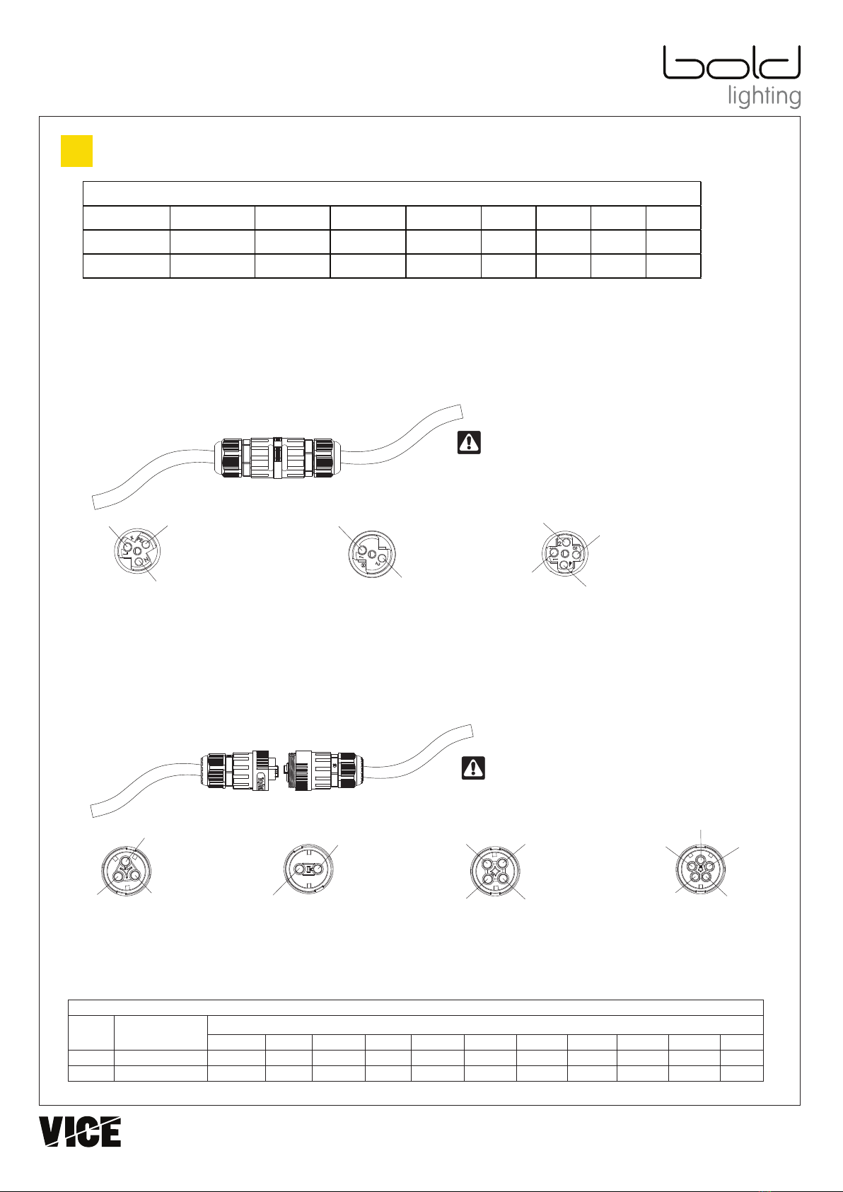
WARNING: THE CONNECTORS PINS LABELING CAN BE FOUND INSIDE
CONNECTOR, EMBOSSED ON THE WIRE TERMINALS. ALWAYS DOUBLE
CHECK FACTORY WIRING ORDER BEFORE CONNECTING TERMINATING
THE CABLES ON-SITE
LINE-TO-LINE CONNECTOR:
When Provided with Line-to-Line Connectors, fixtures will be Type 2 (Daisy chained) as show on page 3 and will have an Input cable and
an Output cable with specific length. These Cables shall be connected and terminated On-site.
Line-to-Line Connectors will have a separate instruction manual included in the fixture’s packaging, giving detailed instructions on how
to connect the leads properly. This step requires following the below wire labeling closely to prevent any damage to the fixtures.
FAILURE TO FOLLOW THE WIRING COLOR CODING AND CONNECTORS PIN LABELING WILL VOID THE FIXTURES WARRNTY
MALE / FEMALE CONNECTOR:
When fixtures are ordered for continuous runs, (Daisy Chained), fixtures will be provided with MALE / FEMALE Connectors. Connectors
are factory installed on Input and Output cables leads.
FAILURE TO FOLLOW THE WIRING COLOR CODING AND CONNECTORS PIN LABELING WILL VOID THE FIXTURES WARRNTY
USA - BOLD LIGHTING Atlanta, GA 30075 +1 (833) 265-3187
Lebanon P.O. Box. 11-0125 - Beirut +961 1 486311
Page 7/7
U50 LIGHTWAY OUTDOOR
Product Installation Guide (Continued)
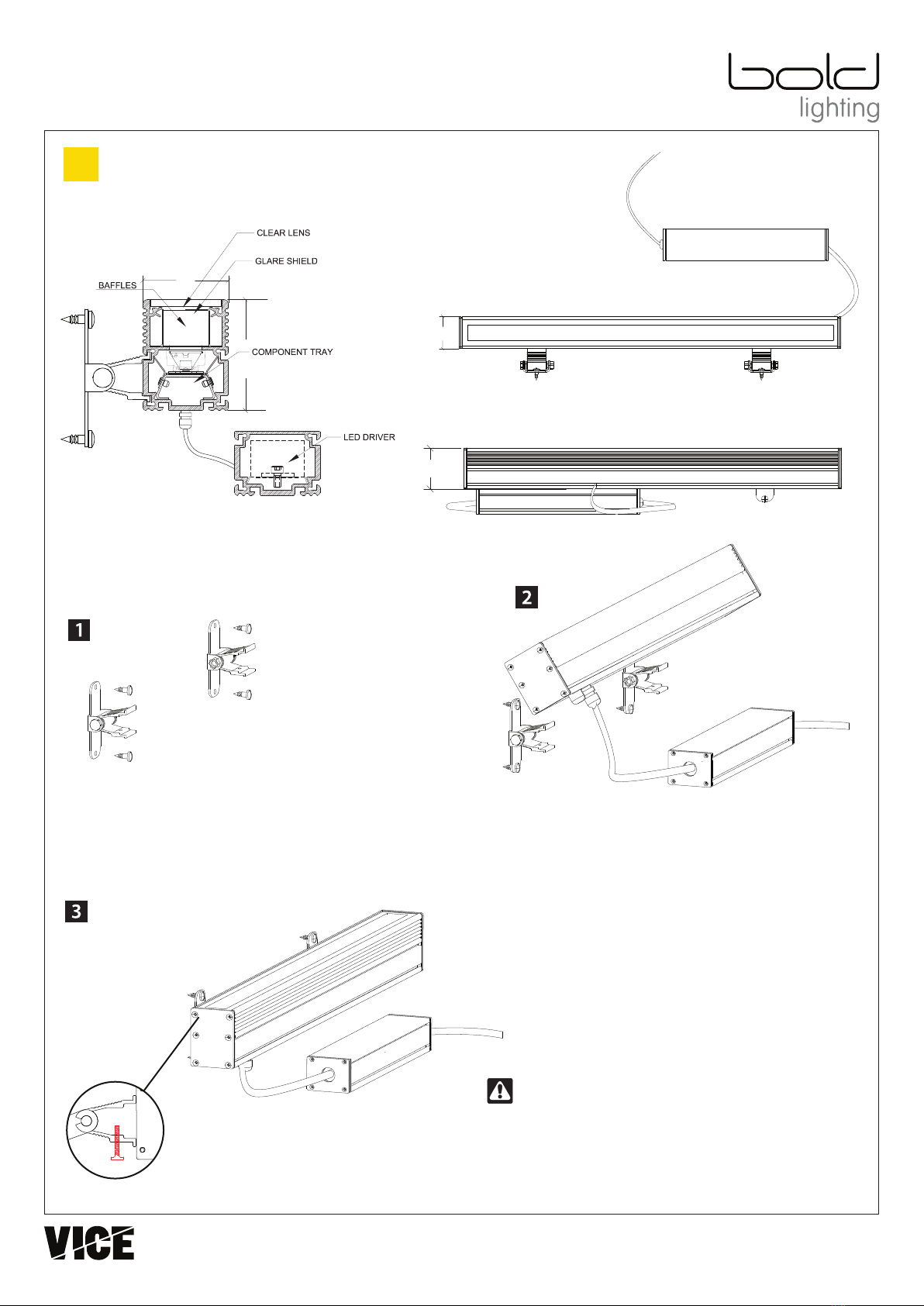
Electrical information
Max daisy chain length (A minimum of 18 AWG or 0.75
2
mm is required)
L1 L2 L3 L4 L5 P1 P2 P3 M1 M2 M3
UL
120VAC - 60 Hz 135 ft 100 ft 70 ft 50 ft 36 ft 70 ft 50 ft 36 ft 54 ft 38 ft 27 ft
CE
220VAC - 50/60 Hz 62 m 45 m 33 m 23 m 17 m 33 m 23 m 17 m 25 m 18 m 13 m
Voltage
System
Male Female
Wiring Instructions (Continued)
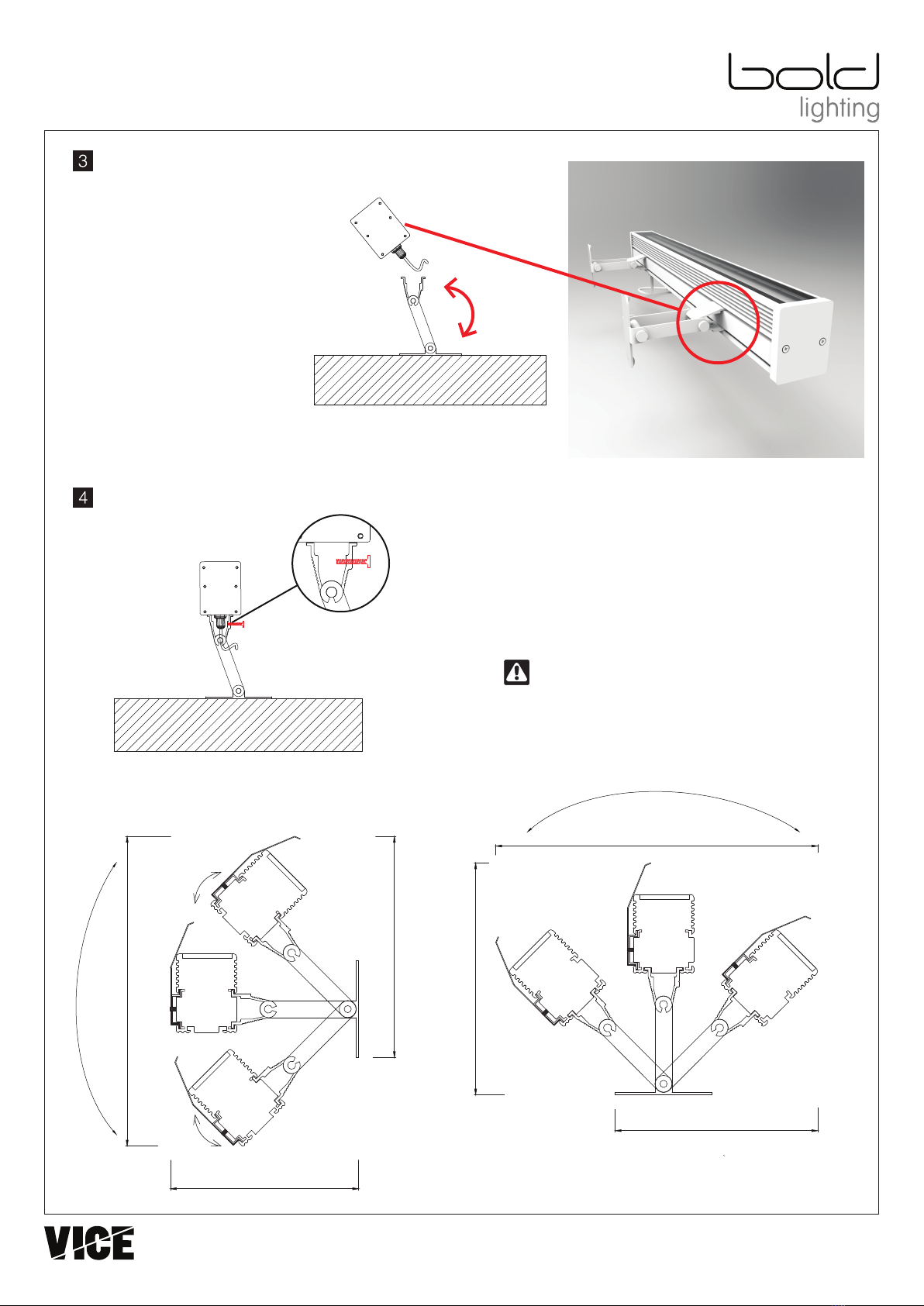
3
FOR 0-10V DIMMING, THE FIXTURE ARE PROVIDED WITH TWO (2) CABLE
LEADS, ONE WITH A 3 PIN CONNECTOR FOR POWER AND THE OTHER WITH
2 PINS CONNECTOR FOR DIMMING WIRES. FOLLOW BELOW CONNECTOR
LABELING FOR TERMINATION OF WIRES
Data -
Data +
Ground
PE
Line
1
3
Data - / DALI
Data + / DALI
2 Neutral
N
Ground
Line
Neutral
3 Pin Female Connector
Upper View
Ground
PE
Line
1
Dimmed
Line
Neutral
N
NON-DIM OR PHASE DIMMING
0-10V DIM OR DMX DATA 3 WIRES DIMMING DALI DIMMING
Data -
Data + Ground
PE
Line
1Dimmed
Line
Neutral
N
Ground
PE
Line
Neutral
N
NON-DIM OR PHASE DIMMING 0-10V DIM OR DMX DATA 3 WIRES DIMMING
GROUND LINE NEUTRAL DIMMED LINE 0-10V + 0-10v - DALI + DALI -
UL System GREEN BLACK WHITE ORANGE RED GREY RED ORANGE
CE System YELLOW / GREEN BROWN BLUE N/A RED BLACK RED BLACK
WIRING COLOR CODES
USA Revision: 1 Apr 2019
Table of contents
Other VICE Outdoor Light manuals
Popular Outdoor Light manuals by other brands

FLOS
FLOS CAPTAIN FLINT Instruction for correct Installation and Use

Sea gull lighting
Sea gull lighting Sevier I installation instructions

HumanTechnik
HumanTechnik lisa operating instructions

Trilux
Trilux Deca LED Future Series Mounting instructions

Orion
Orion AL 11-1180 Mounting and safety instructions

KODA
KODA LM56176 Care & use instructions

GLUCKSTEIN ELEMENTS
GLUCKSTEIN ELEMENTS 39641-HBCLED Use and care guide

Orlight
Orlight Marine Grade ORLLM96 installation instructions

NERI
NERI LIGHT 100 Instruction booklet

Stoane Lighting
Stoane Lighting Surf Type G Installation and maintenance instructions

BEGA
BEGA 84 320 Instructions for use

Polarlite
Polarlite 1558362 operating instructions