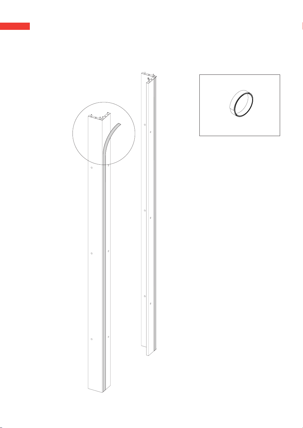
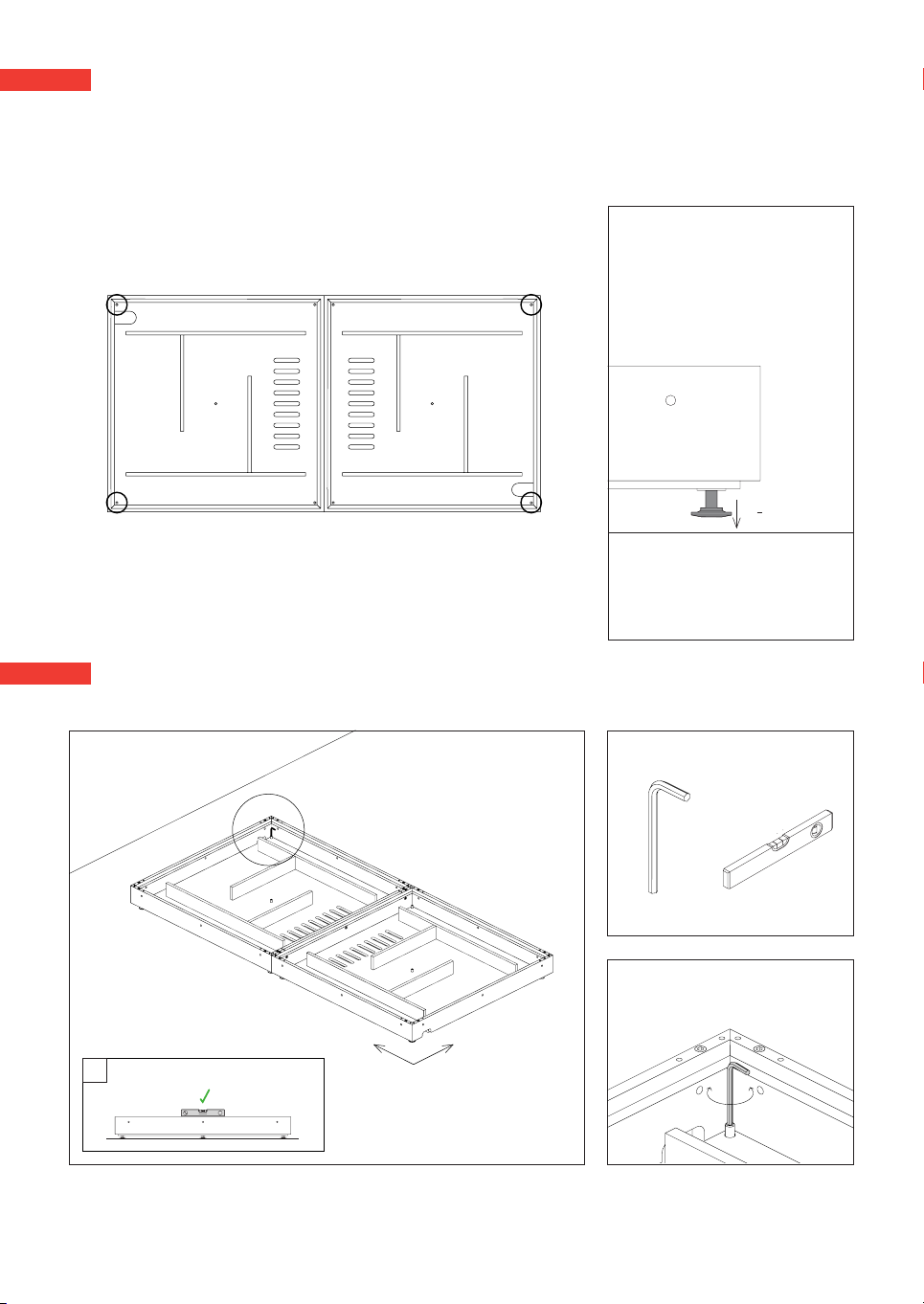
Vicoustic VicBooth Ultra 1x2 User manual

1
1x2
Installation Manual

2

3
Included
Material Needed
Lateral | 5 uni.
Door | 1 uni. Floor | 2 uni.
Ceiling | 2uni.
Structure | 8 uni.
A B C D E F G H I J
Not included
Bubble Level 6mm Phillips Screwdriver | 2 uni.Box Cutter
64 uni. 32 uni. 32 uni. 30 uni. 84 uni. 30 uni. 12 uni. 6 uni. 8 uni. 16 uni.
X
4 mm | 2 uni. 5 mm | 1 uni.
K
6 uni. Foam seal
scissors
1 uni.
W

4
1
2
Remove the oor panels and the 3 PET layers from each of the oor structures.
Place the Floor Structures on the ground according to the diagram.
Trim the supplied foam seal to match the base width.
Apply foam seal on one side of the contact surface to ensure an acoustic seal.
Step’s Material
scissors
Foam seal

5
Step’s Material
Join the oor structures using the 63mm screws (K) and the at heads (E). Use the 4mm Hex Keys (X).
E
K
E
K
3
4
XX
4mm4mm

6
Step’s Material
X5mm Bubble Level
up down
!
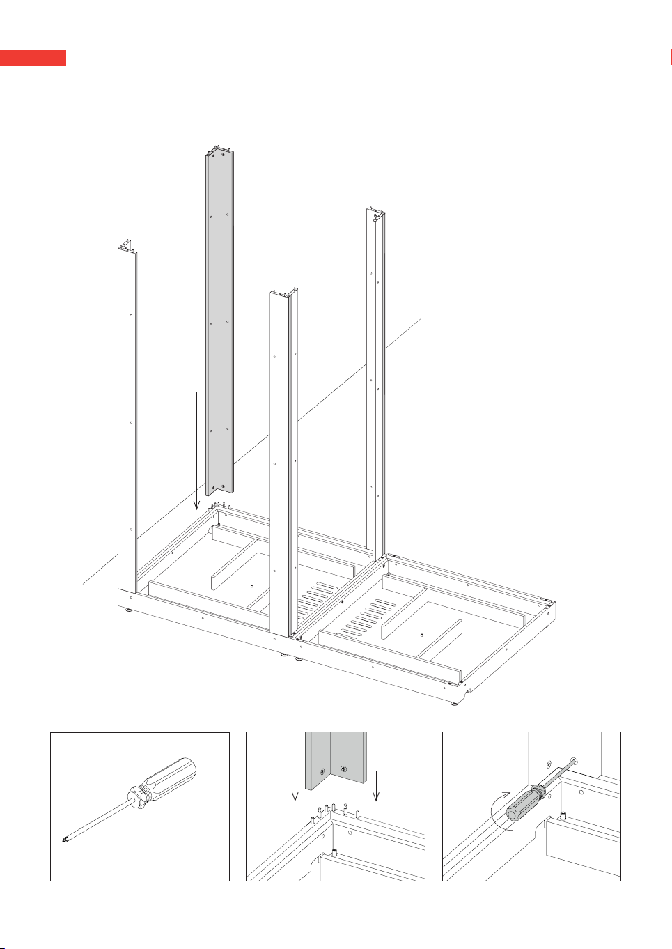
Level the oor structure using the 5mm Hex Key (X), adjusting the four levelers of the outside corners. Once the
structure is levelled on both axes, the levellers that were collected should be adjusted so that they touch the oor.
5
~15mm | 0.59’’
!The precise leveling of the oor structure is crucial for the correct assembly and operation of the VicBooth
Ultra - use a bubble level. Make sure the oor structure is in its nal position - once assembled, the
VicBooth Ultra should not be moved.
Unscrew the four oor levelers of the outside corners of the set to half their length (about 15 mm - 0.59 in),
as shown in the diagram. The other levelers remain retracted.
4

7
Step’s Material
Unscrew the four oor levelers of the outside corners of the set to half their length (about 15 mm - 0.59 in),
as shown in the diagram. The other levelers remain retracted.
6
7
A
B
Insert wooden dowels (A) in the oor structure according to the diagram.
Screw the metal ttings (B) in the oor structure according to the diagram.
Step’s Material

8
8Insert the locking cams (C) in the Structure Pillars and insert the wooden dowels (A) in the top end of the
structure pillars.
Step 2
Step’s Material
C
A
1 uni.
Step 1

9
9Apply the foam seal on one side of the contact surface of the structure pillars to ensure an acoustic seal.
(only applies on 2 pillars, on the side that is in contact between the parts).
Step’s Material
Foam seal

10
10 Fit the structure pillars on the oor structure according to the diagram and rotate the locking cams (C) by hand
using a screwdriver - make sure the beams are completely inserted before rotating the locking cams to the locked
position.
Step’s Material
6mm Phillips Screwdriver

11
11 Join the structure pillars using the 31mm screws (G) and the at heads (E). Use the 4mm Hex Keys (X).
E
XX
4mm4mm
G
Step’s Material

12
Remove the top covers and the ceiling panels from the ceiling structure - the PET and Vicycle layers stay attached
to the top cover.
Trim the supplied foam seal to match the ceilling width.
Apply the foam seal on one side of the contact surface to ensure an acoustic seal.
12
13
scissors
Foam seal
Step’s Material

13
B
Screw the metal ttings (B) in the ceilling structure according to the diagram.
14
15
Step’s Material

14
15 Fit the ceiling structure on top of the structure pillars according to the diagram and rotate the locking cams (C) by
hand using a screwdriver - make sure the structures are completely inserted before rotating the locking cams to
the locked position.
Step’s Material
6mm Phillips Screwdriver

15
17 Fit the side panels - this step must be executed by two persons. Make sure the side panels are placed in the
correct position according to the diagram below. Each side is composed by a PET panel covered with fabric and an
MDF panel with melamine.
16 Join the ceilling structures using the 63mm screws (K) and the at heads (E). Use the 4mm Hex Keys (X).
Step’s Material
E
K
XX
4mm4mm

16
Step’s Material
6mm Phillips Screwdriver
1 | F 4 | F3 | F
8 | D7 | D
10 | D9 | D
12 | D11 | D
6 | F
5 | F 2 | F
D E
FX
4mm
F
E
D
Please follow the order of xing the screws as described in the diagram and the indications concerning the type of
screws to be used. The Side Panels are xed using the 42mm screws (F) on the top and lower ends, and the 28mm
screws (D) on the sides. Use the at heads (E) and the 4mm Hex Keys (X).
Make sure the holes are aligned before placing the screws (You can use two screwdrivers to help align the holes in the
center of the panel). We advise one person to align the panels with the help of the screwdrivers and the other one to
fasten the screws.
Step’s Material

17
18
19
Carefully separate the Door Frame from the Door.
H
E
G
3 | H 5 | H4 | H
12 | G11 | G
2 | G1 | G
10 | G9 | G
8 | H
7 | H 6 | H
Fit the Door Frame using the 45mm screws (H) on the top and lower ends, and the 31mm screws (G) on the sides.
Use the at heads (E) and the 4mm Hex Keys (X).
E
XX
4mm4mm
GH
V
Step’s Material

18
-
+
Use the spacer provided to ensure even spacing of the door frame. Tighten the bolts following the order of xing the screws as
described in the diagram and the indications concerning the type of screws to be used.
20 Fit the door by carefully sliding the hinges down into the hinge shaft on the Door Frame.
You can also use the metal spacer as a bottle opener.

19
In some cases, due to the unevenness of the oor, slight bend can occur on the door frame. It may be necessary to
loosen and/or tighten some xing screws on the door frame so that it stays as parallel as possible to the door and
guarantees perfect contact between the two surfaces.
21
!Please re-check the leveling of the oor structure. If necessary make nal
adjustments to ensure the correct functioning of the door.
22 Place the PET layers in the oor Structures. Fit the oor panels. Make sure the PET layers and the oor panels are
placed in the correct position by checking the diagram.
XX
4mm4mm
Step’s Material

20
J
23 Place the top covers on the ceiling structures according to the diagram. Fit the ceiling panels using the “J” screws.
Fit the ceiling panels using the “J” screws.
Step’s Material
This manual suits for next models
1
Table of contents
Popular Dj Equipment manuals by other brands

LF Illumination
LF Illumination EF300 SERIES Installation instructions manual

Ecler
Ecler MAC70i user manual

Chauvet DJ
Chauvet DJ Green Thinking LFS-5D user manual

Chauvet
Chauvet FXarray Q5 Quick reference guide

Show Tec
Show Tec 30612 Product guide

Viking Stage Lighting
Viking Stage Lighting VK1810 instructions