Videology SFT-10002 User manual

Doc # INS-10002
Issue Date: 06/24/2013
Revision: A
Page 1 of 23
Prior to Using This Document: Videology reserves the right to modify the information in this
document as necessary and without notice. It is the user’s responsibility to be certain they possess the
most recent version of this document by going to www.videologyinc.com, searching for the model
number, and comparing revision letters on the respective document, located in the document’s footer.
For technical assistance with this product, please contact the supplier from whom the product was
purchased.
Videology®Imaging Solutions, Inc. Videology®Imaging Solutions, Europe B.V.
37M Lark Industrial Parkway
Greenville, Rhode Island 02828 USA
Tel: (401) 949 – 5332 Fax: (401) 949 – 5276
North/South American Sales: sales@videologyinc.com
www.videologyinc.com
Neutronenlaan 4
5405 NH Uden, The Netherlands
Tel: +31 (0) 413 256261 Fax: +31 (0) 413 251712
European Sales: info@videology.nl
www.videology.nl
Installation and Operating
Instructions
Software SFT-10002 / SFT-10011
Cameras 24Z704USB / 24Z704USB-F
24Z704USB-SYS
IMAGING SOLUTIONS INC.
Original Equipment Manufacturer
24Z704USB
24Z704USB-SYS
24Z704USB-F

Doc # INS-10002
Issue Date: 06/24/2013
Revision: A
Page 2 of 23
License Agreement (Software):
This Agreement states the terms and conditions upon which Videology Imaging Solutions, Inc. USA and
Videology Imaging Solutions, B.V. Europe (hereafter referred to as "Videology®") offer to license to you the
software together with all related documentation and accompanying items including, but not limited to,
the executable programs, drivers, libraries, and data files associated with such software.
The Software is licensed, not sold, to you for use only under the terms of this Agreement.
Videology grants to you, the purchaser, the right to use all or a portion of this Software provided that the
Software is used only in conjunction with Videology's family of products.
In using the Software you agree not to:
•Decompile, disassemble, reverse engineer, or otherwise attempt to derive the source code for any
Product (except to the extent applicable laws specifically prohibit such restriction);
•Remove or obscure any trademark or copyright notices.
Limited Warranty (Hardware and Software):
ANY USE OF THE SOFTWARE OR HARDWARE IS AT YOUR OWN RISK. THE SOFTWARE IS PROVIDED FOR
USE ONLY WITH VIDEOLOGY'S HARDWARE. THE SOFTWARE IS PROVIDED FOR USE "AS IS" WITHOUT
WARRANTY OF ANY KIND, TO THE MAXIMUM EXTENT PERMITTED BY LAW, VIDEOLOGY DISCLAIMS ALL
WARRANTIES OF ANY KIND, EITHER EXPRESS OR IMPLIED, INCLUDING, WITHOUT LIMITATION, IMPLIED
WARRANTIES OR CONDITIONS OF MERCHANTABILITY, QUALITY AND FITNESS FOR A PARTICULAR
APPLICATION OR PURPOSE. VIDEOLOGY IS NOT OBLIGATED TO PROVIDE ANY UPDATES OR UPGRADES
TO THE SOFTWARE OR ANY RELATED HARDWARE.
Limited Liability (Hardware and Software):
In no event shall Videology or its Licensor's be liable for any damages whatsoever (including, without
limitation, incidental, direct, indirect, special or consequential damages, damages for loss of business
profits, business interruption, loss of business information, or other pecuniary loss) arising out of the use
or inability to use this Software or related Hardware, including, but not limited to, any of Videology's
family of products.

Doc # INS-10002
Issue Date: 06/24/2013
Revision: A
Page 3 of 23
Table of Contents
1. Document History....................................................................................................................4
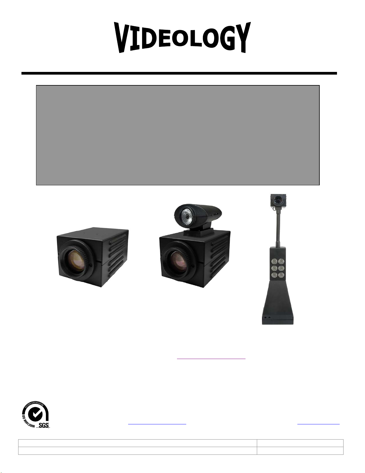
2. General Descriptions................................................................................................................4
3. Specifications..........................................................................................................................5
4. Dimensions.............................................................................................................................6
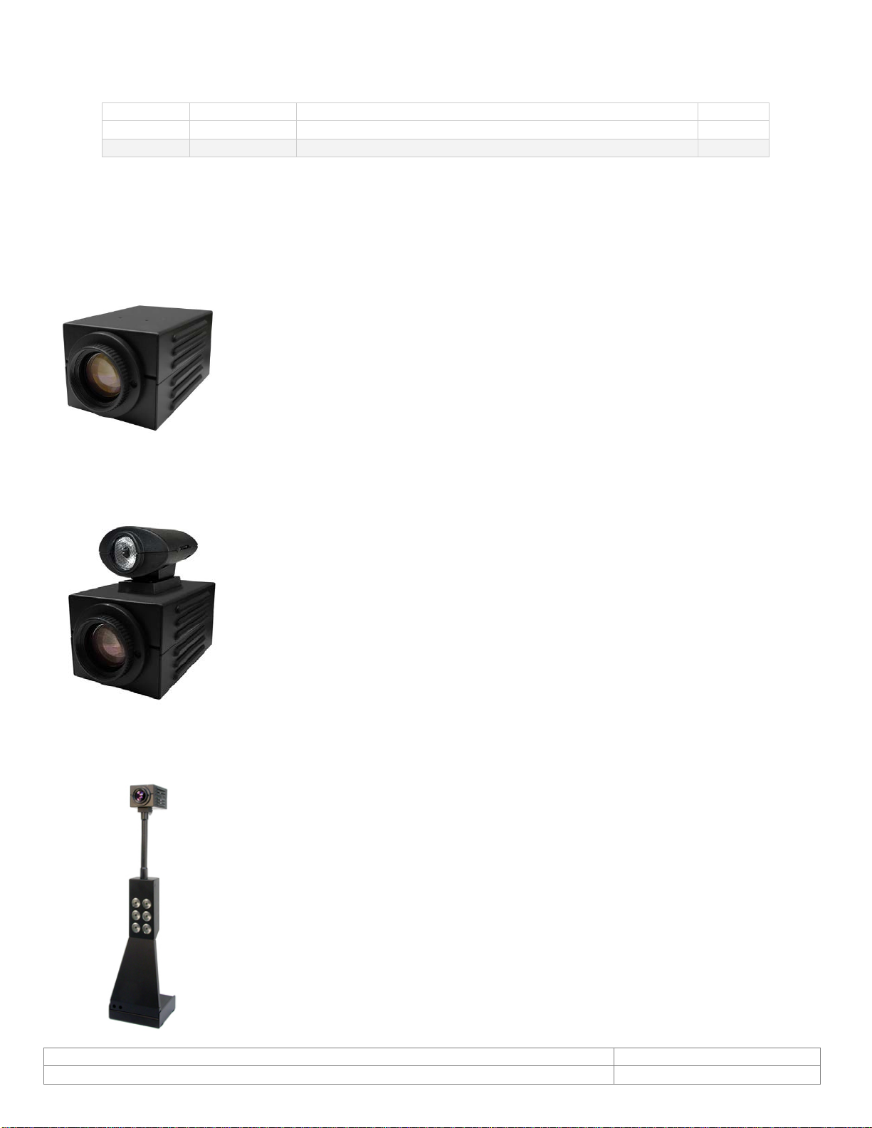
4.1. 24Z704USB......................................................................................................................6
4.2. 24Z704USB-F...................................................................................................................6
4.3. 24Z704USB-SYS...............................................................................................................7
5. Minimum Computer System Requirements..................................................................................8
6. Setup and Operation................................................................................................................9
6.1. Flash Camera Setup (24Z704USB-F) ...................................................................................9
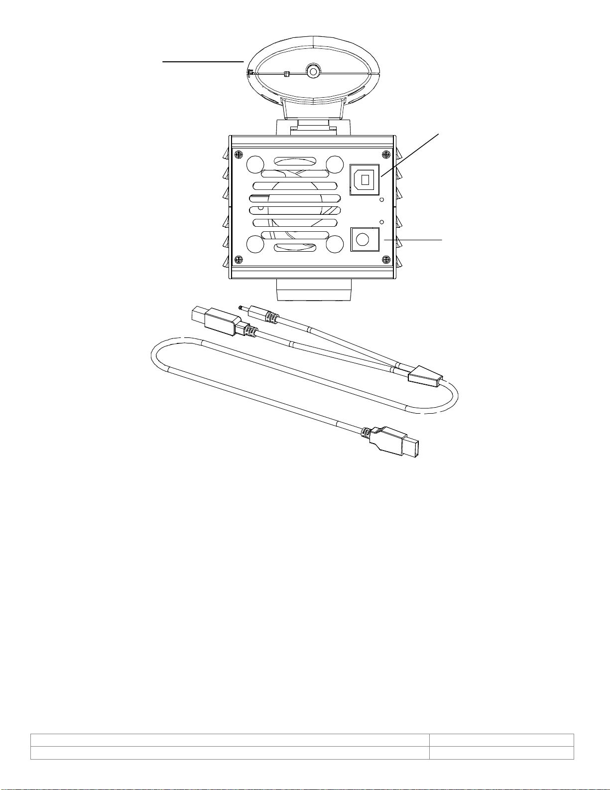
6.1.1. Attaching the Illuminator on top of Flash Camera...........................................................9
6.1.2. Wiring and Power.......................................................................................................9
6.1.3. Subject Distance......................................................................................................10
6.1.4. Flash Intensity.........................................................................................................10
6.1.5. White Balance..........................................................................................................11
6.2. USB System Setup (24Z704USB-SYS)...............................................................................12
6.2.1. Camera Placement ...................................................................................................12
6.2.2. Control Panel...........................................................................................................12
6.2.3. Power Connection.....................................................................................................12
6.2.4. Computer Connection ...............................................................................................12
6.2.5. Illumination Control..................................................................................................12
6.2.6. Securing the System to the table top..........................................................................12
7. Software ..............................................................................................................................13
7.1. SFT-10002 USB Viewer Installation...................................................................................13
7.2. Using the Videology Viewer..............................................................................................15
7.3. Basic Camera Controls.....................................................................................................16
7.3.1. Zoom Control ..........................................................................................................17
7.3.2. Brightness...............................................................................................................17
7.3.3. Exposure Control......................................................................................................17
7.3.4. Image Orientation Control.........................................................................................17
7.3.5. Image Capture Control (Snapshot).............................................................................17
7.4. Advanced Camera Functions.............................................................................................18
7.4.1. Manual White Balance...............................................................................................18
7.4.2. Focus......................................................................................................................19
7.4.3. Shutter Speed .........................................................................................................19
7.4.4. User Presets ............................................................................................................19
7.5. TWAIN Data Source Installation........................................................................................21
7.6. TWAIN USER Interface ....................................................................................................22
8. Contact Information...............................................................................................................23

Doc # INS-10002
Issue Date: 06/24/2013
Revision: A
Page 4 of 23
1. Document History
2. General Descriptions
The camera and system are supplied with a software application for camera viewing and control. An SDK
is also available for users who wish to integrate the viewing and control features into their own
applications.
The 24Z704USB camera is a standalone camera; it is not adaptable to the 24Z704USB-SYS system.
•2 megapixel progressive scan sensor
•WDM, TWAIN, DirectX/DirectShow compatible
•Still image capture with streaming video
•Autofocus, 10x optical zoom
•FIPS 201 compliance (in conjunction with appropriate software)
The 24Z704USB-F camera has a Led Illuminator designed for use with the Videology 24Z704USB
Autofocus Zoom Camera. It uses a powerful white LED to provide very bright scene illumination at
distances up to 20 feet.
•The intensity of the illumination can be varied using a small control wheel
on the side of the illuminator.
•The flash is controlled directly from the PC, and is triggered whenever a
snapshot command is issued. This can be done from within the Videology
Viewer Application, or by implementing the Flash Trigger provided as part
of the camera SDK.
•An In-Line Hub and Control unit is provided so that the flash unit may be
easily retrofitted to existing Zoom Cameras.
The 24Z704USB-SYS is an ID badging system utilizing a 2 Megapixel Autofocus USB Zoom camera
module and high brightness LED illuminator. It is designed for table top use, and provides high quality
streaming video and single frame snapshot capabilities.
•2 megapixel progressive scan sensor
•WDM, TWAIN, DirectX/DirectShow compatible
•Still image capture with streaming video
•Autofocus, 10x optical zoom
•Cool energy efficient white LEDs replace “hot” incandescent light or flash
and last 1000x longer
•On/Off & dimming for LEDs
•No shadows or hotspots due to lighting placement
•Heavy steel construction
•Flexible gooseneck stand
•Small footprint saves table space
•FIPS 201 compliance (in conjunction with appropriate software)
Revision
Issue Date
Reason
CN#
Rev A
06-20-13
Initial release, replacing “24Z704USB family” manual
13-1033

Doc # INS-10002
Issue Date: 06/24/2013
Revision: A
Page 5 of 23
3. Specifications
Environmental
Operating Temp.
-10°C ~ 50°C (recommended 5° C ~ 40° C)
Mechanical
Dimensions (WxHxD)
24Z704USB
66mm x 58.4mm x 114.3mm
(2.6” x 2.3” x 4.5”)
24Z704USB-F
67.3mm x 106.4mm x 113.9mm
(2.65” x 4.2” x 4.48”)
24Z704USB-SYS
13.46cm x 59.69cm x 12.2cm
(5.3” x 23.5” x 4.8”)
Weight
24Z704USB
417g (0.92 lbs)
24Z704USB-F
417g (0.92 lbs)
24Z704USB-SYS
2.31 kg (5.1 lbs)
Software
Viewer (included)
SFT-10002
• WDM device drivers
• DirectX compliant
• TWAIN compliant
SFT-10002-SDK
(optional)
Complete software development kit and support
for OEMs
Recommended System Requirements
Hardware
Pentium IV
2.3GHz +,
1GB hard drive, Intel USB 2.0
Host controller
Software
Windows 7
32 bit, and 64 bit
Windows Vista
32 bit, and 64 bit
Windows XP
Service pack 2+,
DirectX 9.0c or above
Complementary Models
24Z704USB-P
PAL version (50 Hz) camera
24Z704USB-F-P
PAL version (50 Hz) flash camera
24Z704USB-SYS-P
PAL version (50 Hz) system
24Z704USB-KIT
Camera with optional accessories above
24Z704USB-KIT-P
PAL version camera with optional accessories
above
Government Compliance
FIPS 201
In conjunction with appropriate software
Electrical
24Z704USB
24Z704USB-F
24Z704USB-SYS
Image Sensor
1/3” CMOS progressive scan
Active Pixels (HxV)
1280 x 1024
Total Pixels (HxV)
1600 x 1200
Pixel Size
3.0µm x 3.0µm
Scanning System
Progressive Scan
Scanning Frequency (HxV)
19.5KHz x 15Hz
Resolution
800 TVL
Sensitivity
1 lux (30 IRE)
Display Resolution
1280 x 1024
Still Capture
1280 x 1024 pixels
Signal To Noise Ratio
≤40dB (max)
Synchronization
Internal
Scan Mode
Progressive scan
Flickerless Mode
Yes (always on, NTSC/PAL
configurable)
Contour Enhancement
Yes (text mode or image mode)
Mirror Mode
Yes
(horizontal, horizontal + vertical)
Positive/Negative Mode
Yes
Video Output
USB 2.0
Control Communication
USB bus
Shutter Speed
1/20 - 1/1000 sec.
White Balance
Auto/manual
Brightness
Manual
Iris
Auto/manual
Power Supply
12VDC (10 - 14VDC)
Power Consumption
Camera is 1 Amp Max
System is 3 Amps
Special Functions
Freeze,
H/V reverse, save & recall images
Lighting
(24Z704USB-SYS only)
6 lensed super bright LEDs
USB Video
Video Capture
Yes (via software)
High Resolution Still
Image Capture
Yes (via software)
Supported Image Formats
Uncompressed YUV422
USB Bandwidth
USB 2.0

Doc # INS-10002
Issue Date: 06/24/2013
Revision: A
Page 6 of 23
4. Dimensions
4.1. 24Z704USB
The overall dimensions of the camera are shown in Figure 1.
Figure 1. Overall Camera Dimensions
4.2. 24Z704USB-F
The overall dimensions of the flash camera are shown in Figure 2.
Figure 2. Overall USB Flash Camera Dimensions
USB connector
Power
Flash
USB connector
Power

Doc # INS-10002
Issue Date: 06/24/2013
Revision: A
Page 7 of 23
4.3. 24Z704USB-SYS
The heavy-duty steel construction of both the stand and camera housing make for a robust and durable
design. A flexible gooseneck mount permits the camera to be tilted from back to front or side to side.
The overall dimensions of the USB system are shown in Figure 3.
Figure 3. Overall USB System Dimensions

Doc # INS-10002
Issue Date: 06/24/2013
Revision: A
Page 8 of 23
5. Minimum Computer System Requirements
A PC with USB 2.0 compatible port.
USB 1.1 not supported.
MAC is not supported.
Preview only
•PIII- 1.1GHz or above
•128MB of RAM (256MB preferred)
•Windows XP/2000 for USB2.0
•DirectX/DirectShow 9.0c or later
•Windows XP Service Pack 1 (Service Pack 2 Preferred) Windows 2000 Service Pack 4
Preview and capture at the same time
•Full D1 MPEG 2 - P4 – 2.4GHz or above
•640 x 480 MPEG 2 - P4 – 2.0GHz or above
•352 x 288 MPEG1 - P4 – 1.5GHz or above
•Hard Disk - 5400RPM or above (7200RPM preferred)
•128MB of RAM (256MB preferred)
•Windows XP/2000 for USB2.0
•DirectX/DirectShow 9.0c or later
•Windows XP Service Pack 1 (Service Pack 2 Preferred) Windows 2000 Service Pack 4
Verify system has the latest USB 2.0 host driver from Microsoft® only.
Verify that USB host controller chipset is Microsoft certified.
This product is not guaranteed to operate with a USB 2.0 host driver from OWC.

Doc # INS-10002
Issue Date: 06/24/2013
Revision: A
Page 9 of 23
6. Setup and Operation
6.1. Flash Camera Setup (24Z704USB-F)
6.1.1. Attaching the Illuminator on top of Flash Camera
The illuminator is shipped with a mounting foot which is attached to the top of the camera using 2 screws,
as shown in the illustration below.
Attaching the LED illuminator
to the 24Z704 Camera
Flash Unit Mounted on Camera. Note the intensity
control on the side of the flash unit.
Conversely, the LED flash unit may be attached to the camera using the Small Velcro™ pads provided.
With the foot attached to the camera, the illuminator simply snaps into place.
6.1.2. Wiring and Power
The Led Illuminator is provided with an In-Line Control unit that provides both power and control to the
flash and also replaces the existing USB connection to the Zoom camera module, as shown in Figure 3.
Connect the in-line Hub to the camera, flash and PC as shown, and connect the 12DC power to the rear of
the camera.
Zoom Camera
Intensity Control
Flash Unit
Screws
Mounting Foot

Doc # INS-10002
Issue Date: 06/24/2013
Revision: A
Page 10 of 23
In Line Hub and Control Unit Connections
6.1.3. Subject Distance
For best results, the subject should be placed at a distance of not less than 6 feet from the camera. This
will provide uniform, glare free illumination from the flash.
6.1.4. Flash Intensity
The brightness of the LED flash can be adjusted using the small thumb wheel on the side of the flash unit.
Turning the wheel from front to back will reduce the light intensity.
DC Power In
12 VDC
B
USB
A
Flash
A
B
To PC

Doc # INS-10002
Issue Date: 06/24/2013
Revision: A
Page 11 of 23
The intensity setting will vary depending upon the ambient light level and distance from the camera to the
subject so some experimentation may be required to get the correct setting.
6.1.5. White Balance
The 24Z704USB zoom camera has an automatic white balance (AWB) feature which enables the camera to
adjust to varying illumination conditions such as sunlight, fluorescent lighting, incandescent lighting etc.
This AWB feature works well under most circumstances, but if the scene contains a disproportionate
amount of a single color, the color reproduction may be affected.
This may happen if a colored backdrop is used for portrait pictures for example.
A blue back drop, for example, may cause skin tones to become yellowish.
To overcome this problem, manual white balance adjustment should be used. For more information on
this function, refer to the user manual for the 24Z704USB Zoom Camera.
Similarly, if the room lighting is very different in intensity and color temperature from the flash, it may be
necessary to use manual white balance to obtain the best image quality.
Intensity Control

Doc # INS-10002
Issue Date: 06/24/2013
Revision: A
Page 12 of 23
6.2. USB System Setup (24Z704USB-SYS)
6.2.1. Camera Placement
The system is designed for tabletop use, and should be located within 6ft of the PC to which it will be
connected. If necessary, the system may be secured to the table top using the clamps provided (see
figure 4)
6.2.2. Control Panel
Control Panel
6.2.3. Power Connection
The power supply is a universal type, and will operate on any 120/240V 50/60Hz AC supply.
Simply plug the AC power cord into a power outlet and connect the output cable from the power supply to
the DC input jack on the control panel of the system (see Figure 3)
6.2.4. Computer Connection
Connect the system to the computer using the standard USB cable supplied.
6.2.5. Illumination Control
The LED illuminators are housed in the camera stand, and the illumination intensity can be varied using
the rotary control located on the base of the unit. See Figure 3.
We recommend that you do not leave the LEDs on full brightness for an extended length of
time, as this may reduce their lifetime.
6.2.6. Securing the System to the table top
The badging system is supplied with small clamps that can be
used to secure the system to the tabletop. The clamps are
installed into the four rectangular slots in the base and
secured to the table with #6 screws as shown in figure 4.
Securing the System to the tabletop
Power
Brightness
Control
LED
USB Connector
Power Input

Doc # INS-10002
Issue Date: 06/24/2013
Revision: A
Page 13 of 23
7. Software
7.1. SFT-10002 USB Viewer Installation
To install the viewer application on your Windows OS system; Run the SetupPZV.exe program from the
CD provided with the system/camera.
A window pop-up will show asking if you want to install the Videology Power Zoom Viewer and the Flash
Unit Driver.
For 24Z704USB cameras and 24Z704USB-SYS USB systems
☒Videology Power Zoom Viewer
For 24Z704USB-F cameras, check both checkboxes.
☒Videology Power Zoom Viewer
☒24Z Flash Unit Driver
Click Install.
The following dialog box will appear.

Doc # INS-10002
Issue Date: 06/24/2013
Revision: A
Page 14 of 23
If you wish to install the viewer in a location other than the default directories, click on the Browse button
and specify the desired location, otherwise click on the Install Button, and the following screens will
appear
Click Close.
Simply connect the camera to a USB (2.0) port on your computer and launch the viewer
from the desktop icon.

Doc # INS-10002
Issue Date: 06/24/2013
Revision: A
Page 15 of 23
7.2. Using the Videology Viewer
After software installation, plug in the USB cable from the camera. A window will pop up stating that
Windows is installing the device drivers:
Upon completion a second window will state the driver software installed successfully:

Doc # INS-10002
Issue Date: 06/24/2013
Revision: A
Page 16 of 23
7.3. Basic Camera Controls
After software installation, open the PowerZoom software
NOTE: Allow a few seconds after connecting the camera to the USB port. The camera is ready for
operation when #1 appears in the box next to the Start button.
Click on the START button in the top left hand corner and the camera image will appear.
The viewer includes basic controls for adjusting the Zoom Level, Brightness, Exposure Mode and White
Balance Settings of the camera.
Also included within the basic control panel are the Image capture controls:
Basic Viewer Control Panel
Image Orientation
Control
White Balance and
Exposure Control
Image Capture
Control
Camera is ready
when the #1 appears
Zoom and
Brightness Control

Doc # INS-10002
Issue Date: 06/24/2013
Revision: A
Page 17 of 23
7.3.1. Zoom Control
The Zoom control simply adjusts the level of magnification and thus the angular field of view of the
camera. To zoom in or out, simply press and hold the up or down arrow (see figure 5) until the required
field of view is obtained.
7.3.2. Brightness
The brightness control adjusts the overall image brightness. To increase or decrease the brightness of the
image, simply press and hold the up or down button (see figure 5) until the required image brightness is
obtained.
7.3.3. Exposure Control
If the Auto Exposure control is checked, then the camera will automatically adjust to variations in light
intensity by opening or closing the aperture of the lens.
If the Auto Exposure button is unchecked, then the lens aperture will remain at its current setting. It is
recommended that the Auto exposure mode be used for most applications, and this is the default setting.
7.3.4. Image Orientation Control
The image orientation control allows the user to flip the image either horizontally or vertically.
7.3.5. Image Capture Control (Snapshot)
Single frame images can be acquired and stored to a preset directory. Still image frames can be stored
either as Bitmap (BMP), Graphics Interchange Format (GIF), Joint Photographic Experts Group (JPEG), or
Portable Network Graphics (PNG) files.
To set the location of the stored images select the “Change Snap Folder” option on the left hand side of
the screen. Use the drop-down menu below this to select the required image format.
To acquire an image, simply hit the Snapshot button on the left hand side of the viewer screen.

Doc # INS-10002
Issue Date: 06/24/2013
Revision: A
Page 18 of 23
7.4. Advanced Camera Functions
To access the Advanced Camera Functions, press “Ctrl D” on the keyboard.
The following screen options will appear:
Advanced Image Controls
The advanced function menu allows you to adjust the following parameters:
7.4.1. Manual White Balance
The manual white balance controls allow you to change the way in which colors are displayed.
When using different types of lighting (fluorescent lights, incandescent lamps, sunlight etc.) color tones
can vary, and to get the best color representation, it may be better to override the auto white balance
feature of the camera and adjust the red and blue gain channels to achieve optimum color balance of the
subject.
Manual White
Balance Controls
Shutter
Speed
Focus
Controls
Save
Button

Doc # INS-10002
Issue Date: 06/24/2013
Revision: A
Page 19 of 23
For example, the color of objects viewed under incandescent lighting are shifted towards the red, whereas
Fluorescent lighting can make objects appear bluer.
There are two modes of operation of the White Balance control, automatic (AWB) and manual.
In automatic mode the camera will adjust the colors automatically as the lighting conditions change.
In manual white balance, the user can adjust the color settings to obtain the best color reproduction.
NOTE: The manual color controls are only accessible via the Advanced Camera Functions.
7.4.2. Focus
The 24Z704USB Badging camera is capable of focusing in both Automatic Mode and Manual Mode. It is
important to note that the camera defaults to the setting previously set in either Videology Viewer Mode or
Badging Software Mode.
Because of this, it is important to always set the radio button for the Focus Control to your preference
(Auto Mode/Manual Mode) when using the camera for the first time. (See Figure 6)
7.4.2.1. When Autofocus Fails
Occasionally the camera may have difficulty focusing especially in marginal lighting environments.
Low contrast subjects, blue backgrounds or solid color walls, highly reflective subjects, or subjects in front
of a very detailed background, may require adjustments to focus.
In these situations it is best to set the camera from Auto Mode to Manual Mode and adjust the focus.
Alternatively, the user can zoom out a bit in Auto Mode, which will cause the camera to refocus.
7.4.3. Shutter Speed
The shutter speed sets the integration time of the camera; this is analogous to the speed of a mechanical
shutter on a conventional camera.
To increase or decrease the shutter speed, simply press the up or down arrow.
Each time you press the arrow, the shutter speed will be incremented by one step.
A slow shutter speed should be used in low light conditions; a faster shutter speed should be used if the
subject is moving quickly or under excessive light conditions.
7.4.4. User Presets
When first setting up the 24Z704USB camera you may wish to establish Presets. The badging camera has
8 presets available that allow focus, white balance, etc. to be set for easy retrieval in subsequent camera
usage.
It is recommended that before saving a preset, the Manual radio button be set so that the camera “locks”
in the desired Field of View immediately when a preset is retrieved.
To save the current camera settings, simply click on the “Save Preset” button, and select one of the
presets 1 through 8.
NOTE the save function is only available through the advanced control panel (see figure 6), although the
preset can be recalled (loaded) via the basic control panel.

Doc # INS-10002
Issue Date: 06/24/2013
Revision: A
Page 20 of 23
User Preset Options
To restore the camera to the factory default settings, select the Factory Reset option from the drop down
list on the load presets menu.
Load Preset
Menu
This manual suits for next models
4
Table of contents
Other Videology Digital Camera manuals

Videology
Videology 20D436 User manual

Videology
Videology 20C40xW User manual

Videology
Videology M14 Board User manual

Videology
Videology 20B40x Family User manual

Videology
Videology 20E709TDN3 Installation manual

Videology
Videology 20C20XW User manual

Videology
Videology 24Z2.1W-10X-EXSDI User manual

Videology
Videology 20Z704 USB Installation and operating instructions

Videology
Videology 24C708AF User manual

Videology
Videology 20E20X User manual