Instruction manual - English - EN
5MNGCMMXCAM_1905_EN
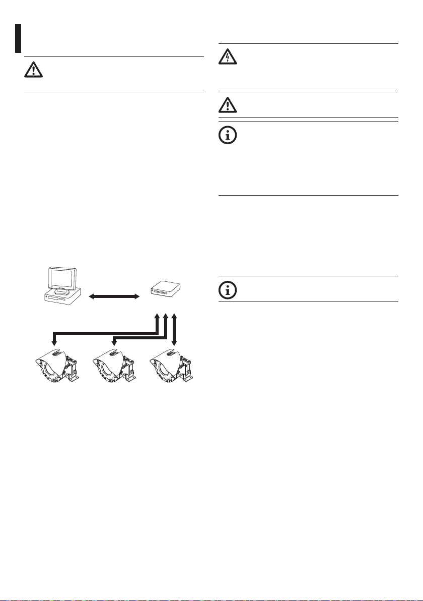
1 About this manual
Install the product following all the
operations outlined in the manual below.
The following manual should be consulted
after conducting all the operations
indicated in Manual A.
Read all the documentation supplied carefully before
installing and using this product. Keep the manual in
a convenient place for future reference.
This document has been compiled and published
using product descriptions and specications
available at the time of publication. The contents
of this document and the specications of the
products discussed herein are subject to change
without notice. Avigilon Corporation reserves the
right to make any such changes without notice.
Neither Avigilon Corporation nor any of its aliated
companies: (1) guarantees the completeness or
accuracy of the information contained in this
document; or (2) is responsible for your use of, or
reliance on, the information. Avigilon Corporation
shall not be responsible for any losses or damages
(including consequential damages) caused by
reliance on the information presented herein.
1.1 Typographical conventions
DANGER!
High level hazard.
Risk of electric shock. Disconnect the
power supply before proceeding with any
operation, unless indicated otherwise.
DANGER!
Hot surface.
Avoid contact. Surfaces are hot and may
cause personal injury if touched.
CAUTION!
Medium level hazard.
This operation is very important for the
system to function properly. Please read
the procedure described very carefully and
carry it out as instructed.
INFO
Description of system specications.
We recommend reading this part carefully
in order to understand the subsequent
stages.
2 Notes on copyright and
information on trademarks
The mentioned names of products or companies are
trademarks or registered trademarks.
AVIGILON, the AVIGILON logo, and AVIGILON
CONTROL CENTER are trademarks of Avigilon
Corporation.
Other names or logos mentioned herein may be the
trademarks of their respective owners.
The absence of the symbols ™ and ® in proximity to
each trademark in this document or at all is not a
disclaimer of ownership of the related trademark.
ONVIF® is a trademark of Onvif, Inc.
3 Identication
3.1 Product marking
See the label attached to the product.
4 Installation
CAUTION! Device installation and
maintaining must be performed by
specialist technical sta only.
The external multipolar cable shield
(armature), if present, must be earthed.
During installation, remember to comply
with the curvature radius of the multipolar
cable (if present).
Minimum bending radius: 190mm (7.5in).
4.1 Range of use
The installation temperature range is: from -
40°C (-40°F) up to +65°C (149°F) or +70°C (158°F)
(depending on the temperature class of the product).
The device operates within a temperature range of:
from -40°C (-40°F) up to +55°C (+131°F) in enclosed
space; from -40°C (-40°F) up to +60 °C (+140 °F), with
ambient convection.