
1
IMPORTANT–Prière de Lire et de Suivre !
• L’installateurdevralaissercesdirectivesauclientquidevralesconserverpourl’usaged’uninspecteurlocaletpour
référenceultérieure.
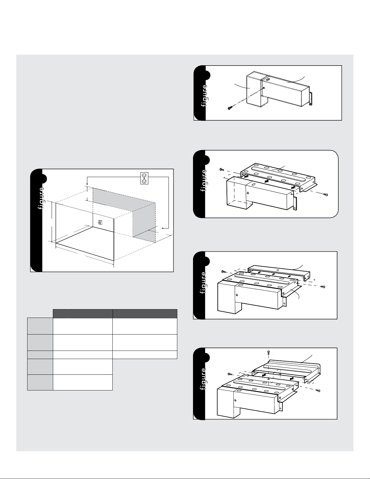
MinimumCutout Opening Width 24-3/8" (619.13 mm)
MaximumCutout Opening Width 24-11/16" (627.06 mm)
MinimumCutout Opening Height 16
-
3/4"(425.5 mm)
MaximumCutout Opening Height 17" (431.8 mm)
Maximum Height distancebetween holes 14-1/4" (361.825 mm)
Distancebetween centerline to holes
12-13/16"(324.65 mm)
Distancebetween holes A25-9/16" (649.3 mm)
Distancebetween centerline to holes
14-5/16"(362.75 mm)
Distancebetween holes B28-9/16" (725.5 mm)
15-13/32"(391.45 mm)
Center Line
BUILT-IN TRIM KIT TEMPLATE
FOR CUSTOM SERIES MICROWAVEOVEN 1. Alignthe mounting template center line with the center of the cutout
andthe floor line with the floor of the cutout. Tape it into place.
2. ForVMTK272, predrill 4 holes marked Awith a 1/16" drill bit.
ForVMTK302, predrill 4 holes marked Bwith a 1/16" drill bit.
3. Removetemplate from the cabinet.
TINSKB182MRR0
Floor Line of Cutout Opening
USE THIS SIDE OF TEMPLATEFOR MODELS
VMTK272 and VMTK302 ONLY.
1-5/32"
(29.6mm)
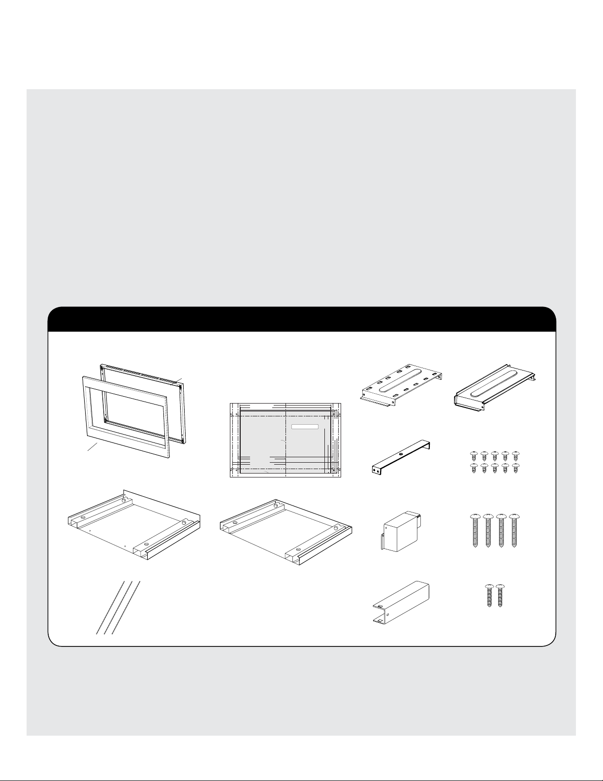
Pièces Comprises dans le Kit VMTK
1
1
1
1 *
Vis A (1/2 po )
10 *
Vis B (1-3/4 po
) 4
Gabarit à montage en surface
2 faces de 27 & 30 po
ou gabarit à montage en
surface simple face de 36 po
QTÉ 1
Coussin QTY 3
Conduit (A)-1 1 * Conduit (A)-3 1 *
Conduit (B) 1 *
*
Conduit (C) 1 *
Conduit (A)-2 1 *
Vis C (3/4 po )
2
UNIQUEMENT.


M Service manual")


