Villagepump 500 Standard User manual

O&M Manual v.1.42 October 2017
1
Operation and Maintenance Manual
Villagepump 500 Standard
Villagepump 500 Standard, the leading solution for producing clean
drinking water without the need of any external energy source.
Villagepump BV
Lisdoddelaan 80
1087 KA Amsterdam
The Netherlands
info@villagepump.org
www.villagepump.org
+31 20 620 09 58

O&M Manual v.1.42 October 2017
2
Inhoud
1Introduction........................................................................................................................3
2Unpacking and handling.....................................................................................................4
3Installation Villagepump 500 Standard..............................................................................7
4Preparing Villagepump 500 Standard for first use.............................................................8
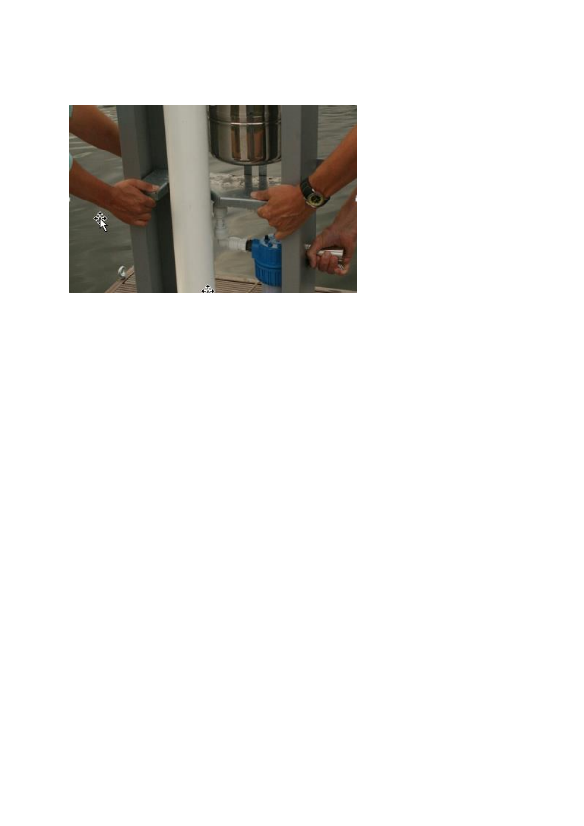
4.1 Mounting Pump Handle and adjusting the Feed Pump...............................................8
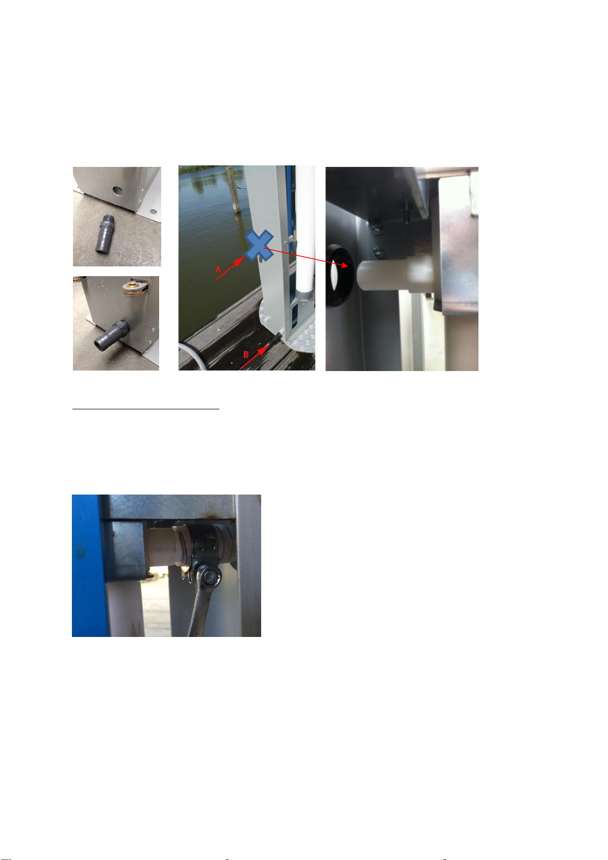
4.2 Connecting Inlet Hose and Drain Hose.......................................................................9
4.3 Connecting Mesh Filter ............................................................................................. 10
4.4 Assembling Activated Carbon cartridge (optionally)................................................10
5First use ............................................................................................................................12
5.1 Pumping up water first time and first backwash cycle..............................................12
5.2 First back-wash is not working..................................................................................13
6Maintenance .....................................................................................................................16
6.1 General.......................................................................................................................16
6.2 Cleaning Mesh Filter ................................................................................................. 16
6.3 Disinfect the Villagepump with a chlorinated detergent...........................................17
6.4 Replacing Activated Carbon cartridge (optionally)...................................................18
6.5 Replacing UF Membrane........................................................................................... 19
6.6 Exchanging Valve......................................................................................................20
6.7 Cleaning system and valve ........................................................................................23
6.8 Storage of Villagepump and/or UF membrane for a longer term..............................24
6.9 Cleaning the UF membrane....................................................................................... 24
7Protocol water analysis.....................................................................................................25
7.1 Preliminary analysis ..................................................................................................25
7.2 Regular Analysis........................................................................................................25
8Troubleshooting ...............................................................................................................27
9Datasheet Villagepump ...................................................................................................28
10 Limitation of warranty and liability .................................................................................29
11 Contact / helpdesk / ordering spare parts .........................................................................30

O&M Manual v.1.42 October 2017
3
1 Introduction
The Villagepump 500 yields up to 500 litre of fully purified drinking water an hour, meeting
WHO standards regarding the removal of bacteria's, viruses and turbidity. This manual -
version 1,42, October 2017 - is meant for Villagepumps with serial number VP500S-07-
XXXXXX-XXX –series 7 or higher, manufactured at March 31, 2017 or later
Schematic drawing of the Villagepump 500 standard.
1. Inlet hose
2. Drain (Outlet)
3. Feed Pump
4. Activated Carbon filter
5. 0,05 mm Mesh Filter
6. Backwash buffer
7. Ultra-Filtration (UF) membrane
8. Valve
9. Disinfectant dispenser
10. Pump Handle
11. Backwash pressure indicator (manometer)
12. Tap
13. Water Meter (𝑚3)

O&M Manual v.1.42 October 2017
4
2 Unpacking and handling
The installation of the Villagepump should be performed by at least 2 people to move and
install the Villagepump properly and safely.
Required tools for installation (this tools are included in standard delivery):
- open-end wrenches (10/11, 12/13, 16/17)
- screwdriver flat 4 - 6 mm
- Allen keys 3, 4 and 6 mm
In case of any doubts or questions, please contact your local distributor. Look for other
possible contacts or information at www.villagepump.org.
The standard package includes the following components:
- Villagepump
- Pump Handle (blue)
- Mesh Filter 0,05 millimetre
- Foot Plate
- Drain Hose, length 1 meter
- Inlet Nose, length 10 meter
Inside the Villagepump:
- Padlock
- Chlorine dioxide tablets (120 pcs of 1 gr or 30 pcs of 4 gr)
- Tool Set (Allen keys, wrenches)
- Grease (Silicon Compound)
- Hose Nipple and Hose Clamps (3x)
- Floater and Tie Wrap
- Spacers length 3 cm
- M8 bolt for mounting Pump Handle (2x)
- Self-locking M8 nuts and rings (4x)
- Manual
And optionally:
- Activated Carbon filter cartridge 20"
- Wrench for 20” Activated Carbon housing
For specific client related reasons this standard configuration might have been changed.
Standard packaging Villagepump 500

O&M Manual v.1.42 October 2017
5
The Villagepump is strapped onto a pallet further protected by a cardboard box.
- Open the box at the upper side and take out carefully any loose parts;
- Remove the packaging from the pallet and ensure environmentally friendly disposal;
- Unpack the remaining loose (spare) parts like Pump Handle, Activated Carbon cartridge
(optionally), Foot Plate, Mesh Filter and Hoses.
- Untie the Villagepump from the pallet and put the Villagepump carefully upright on a stable,
flat surface;
- Remove the tie-wrap that locks the Villagepump and remove the plastic bag.
- Unlock the cover (at the right sight) by pushing down the small handle; unpack the loose
parts that are stored inside the Villagepump like the Floater, Toolset, Manual, Fasteners,
ClO2 tablets etc.
- Remove both white plastic covers. Without these covers the Villagepump is easier to pick
up and move. The covers can easily be lifted vertically from their hinges. One cover (the right
one) is locked on the outside, the other cover (the left one) is locked from the inside. First
open the cover that is locked on the outside, enabling you to unlock the other cover.
Internal lock of one cover; unlocking the covers by lifting the covers from the hinges;

O&M Manual v.1.42 October 2017
6
- Move the Villagepump always with at least two people and use the tap and the centre
console as targets.
To move the Villagepump, please use tap and centre console.

O&M Manual v.1.42 October 2017
7
3 Installation Villagepump 500 Standard
The Villagepump 500 Standard is suitable for low or average polluted surface water,
rainwater harvesting, ponds and streams.
Please note that:
-the bottom of the Villagepump should be mounted not more than 3 meters above the
water level (maximum static head of 3 meter);
- the length of the Inlet Hose that is included in the delivery, is 10 meter. This is the
maximum distance to be covered with the priming system of the Villagepump.
- Install the Villagepump on a flat, hard (concrete, metal, wood) smooth and level surface,
with a minimum size of 60 by 120 cm.
- A Foot Plate / Installation Frame is delivered together with the Villagepump 500 Standard,
with the studs (M8) at the right position (distance 40 x 25 cm). This footplate should be
mounted on a sturdy, flat floor or can be moulded in a cement of concrete base. If you
choose this option, please take care that the bolts are at least 45 mm above the surface of
the cement/concrete base.
Installation Plate / Foot Plate with four M8 rods
- Apply the supplied spacers (length 3 cm) to the studs / bolts; place the Villagepump over
the studs / bolts and secure it with four self-locking M8 nuts. The Villagepump is now firmly
anchored to the floor.

O&M Manual v.1.42 October 2017
8
4 Preparing Villagepump 500 Standard for first use
Once installed the Villagepump 500 Standard has to be prepared for first use. Follow the
instructions below:
- Mounting Pump Handle and adjusting the Feed Pump (see par 5.1)
-Connect Inlet Hose and Drain Hose (see par 5.2)
-Connect Mesh Filter to Inlet Hose (see par 5.3)
- Install Activated Carbon (AC) cartridge (optionally)
Please note: install the AC cartridge only after the Villagepump has been used already
for at least 2 back wash cycles (see par 5.5)
4.1 Mounting Pump Handle and adjusting the Feed Pump
The blue Pump Handle is packed separately and has to be mounted. Find below the
instructions.
- Unpack the Pump Handle and put the Pump Handle in the aluminum block.
Mounting pump handle
- Attach the Pump Handle firmly with 2 supplied bolts (use 5 mm Allen key). Pump a few
strokes and check the bolts.
At installation, the Fork of the Feed Pump has been mounted usually at the first hole of the
lever (closest to the handle) This leads to the lightest way of pumping.
Fork installed at third hole of lever.

O&M Manual v.1.42 October 2017
9
If the distance (static head) between Villagepump and water level is higher than 3 meters, we
recommend to put the Fork on the second or third hole. The Feed Pump will create a higher
vacuum and more water can be primed from a higher level.
4.2 Connecting Inlet Hose and Drain Hose
Mounting hoses for inlet (A) and drain (B)
Connecting the Inlet Hose (A)
The Inlet Hose is directly connected to the Feed Pump, through a hole in the frame.
- Put the Inlet Hose through the hole and put the Hose Clamp on the hose.
- Push the Inlet Hose from outside over the nipple as far as possible.
- Shift the Hose Clamp at the right spot and connect the Hose Clamp firmly!
Note: be aware that this connection should be completely air-tight because the Feed
Pump operates with a vacuum.
Note: keeping the Inlet Hose out of full sunlight will extend the life time. We
recommend to bury the Inlet Hose in the ground or cover the hose with sand of other
materials

O&M Manual v.1.42 October 2017
10
Connecting drain hose (B):
- Mount the Hose Nipple to the plastic part inside the Villagepump firmly.
- Fit the Drain Hose (1 meter length is delivered standard) as far as possible on the Hose
Nipple and connect the hose firmly with a hose clamp (B).
4.3 Connecting Mesh Filter
Note: shorten the Inlet Hose to the minimal length needed, especially when the water
level is 3 or more than 3 meters below the level of the Villagepump.
- Fit the Inlet Hose to the Mesh Filter using a Hose Clamp and connect it firmly. Check
carefully if the Mesh Filter is really connected well!
Note: please be aware that this connection should be completely air-tight because the
feed pump operates with a vacuum.
- Attach the Floater to the Mesh Filter with for instance a tie wrap (included in standard
delivery)
- Place the Mesh Filter in the water and make sure it is under water but not in mud or soil.
Mounting the Mesh Filter to the hose; connect the floater to the Mesh Filter with for instance a tie wrap
in order to keep Mesh Filter just below the water surface.
4.4 Assembling Activated Carbon cartridge (optionally)
Note: Activated Carbon (AC) filter cartridge is usually not installed. If the cartridge is
installed, remove AC filter cartridge before the first use. Every new UF Membrane is
shipped filled with Glycol to protect it from freezing. Glycol is harmful for the AC filter
cartridge. At least 3 backwash cycles are needed to be sure to dispense the UF
Membrane of all Glycol.

O&M Manual v.1.42 October 2017
11
After you have pumped for at least two backwash cycles, install the AC filter cartridge.
- Unscrew the housing from the holder (use the special wrench, included in delivery)
- Put the 20" AC filter cartridge in the housing
- Re-install the housing, take care of a proper placement of the 0-ring.
Installing AC filter cartridges: 2 x 10" or 1 x 20"
- Fit the covers to the Villagepump by inserting them into the hinges and close it with the
supplied padlock.
The Villagepump is now ready for first use! See next chapter for instructions for first use.
Note: be aware when the demo unit is not used for a longer time, the case for most
demo units. An used/wet Activated Carbon cartridge, not used for several days or
longer, could become a source for bacterial contamination because the water is
standing still in the cartridge at often high temperatures. Any bacteria entering the
system could grow rapidly in this circumstances. The activated carbon cartridge
performs well, when it is used on a daily base. So when you give demonstrations with
the AC filter installed, be aware of this, and in case of any doubt, please replace
the AC cartridge with a new one, taking off the plastic wrapper immediately before
installing and preferable not touching the filter components with bare hands.

O&M Manual v.1.42 October 2017
12
5 First use
5.1 Pumping up water first time and first backwash cycle
If the Villagepump has been installed, the Pump Handle mounted and the Mesh Filter is in
the water, you can start pumping. Depending on the length of the hose (and if the blue fork is
on the first or second or third hole of the lever), it takes some time before the first water is
coming out of the tap.
Note: at the start you will only pump air and this will take some time, especially when
the hose is 10 meters or the distance to the water level is higher than 3 meters. We
recommend to open now and then the dispense unit at the Valve (Black Screw Cap)
and leave out some air during this procedure. Also during the first backwash some
water/air will come out the system (tap/drain). However after one or two back wash
cycles the air will be out of the system.
Open Screw Cap of the dispense unit of the Valve at first time pumping up water to release the air.
- When you start pumping, the pressure indicated on the manometer will slowly advance to
about 2,9 –3,6 bar. In normal use, this will take about 5 - 10 minutes or producing 30 to 40
litres of water.
Manometer, indicating the pressure of the Back Wash Buffer (collecting the water for the back wash)
- Once the pressure has reached in between 2,9 –3,6 bar, the UF membrane is
automatically flushed, the so called "backwash". At the moment of backwashing, you will
notice that the indicator in the manometer is falling and water is flushed with great power
through the drain hose.
- Please note: do not pump during backwash. Although not harmful for the system,
water will leave the system via the pressure relief valve indicated at the picture below.

O&M Manual v.1.42 October 2017
13
Pressure relief valve: releases water if the pressure at the UF membrane has exceeded 0,7 bar and/or
when pumping during backwash
Backwashing takes about 30 - 60 seconds and stops automatically. The backwash has
stopped once the indicator on the manometer has dropped to between 0 –1 bar and only a
trickle of water comes out of the drain hose.
- Once the backwashing is completed, you can continue with pumping and purifying water.
5.2 First back-wash is not working
Note: due to transport and/or storage or not using the Villagepump for a longer period
it could occur that the (first) backwash is not working and the pressure reaches 4 bar
or more. If the pressure reaches more than 4 bar, water will come out of the pressure
relief valve with the red knob (see picture below)
Pressure relief Valve: in operation when pressure in the system exceeds 4 bar
If this situation occurs, please follow instructions below.
- When the pressure is reaching 4 bar,unlock the padlock, open the cover and give a gentle
slab on the metal valve cover (indicated by green colour in the picture below). Usually the
valve opens and the Villagepump starts back-washing. Next time the pressure should be
between 2.9 and 3.6 bar.
However if this does not work, follow the instructions below.
- Open the small blue valve/tap (close to the valve) to release the pressure; the barometer
will go down to app. 1 bar; close the valve/tap again.

O&M Manual v.1.42 October 2017
14
-Remove the metal valve cover, indicated by green colour in the picture below.
Remove the metal valve cover, open the blue tap to release pressure (and close again) and remove
the transparent piston cover
- Remove the transparent piston-cover of the valve –the piston-cover is a transparent plastic
part, indicated by a red arrow in the picture above –remove the cover by pushing and
turning counter clockwise but be aware that the piston will come out with great force due to
the spring and some water will come out!
- Disconnect the piston cover from the blue plunger; when rust is visible please remove.
- Push the blue plunger in the valve to make sure it does no stick to the cylinder wall. The
plunger will come out by itself again due to the spring behind the plunger. Repeat this a few
times.
- Put the piston with the spring into the right position. Be aware that there is only one way to
re-position the piston in the right position. There is a small mark (see red arrow in the
picture). The piston should be positioned in such a way that the mark is on top (Mark x).
Mark x

O&M Manual v.1.42 October 2017
15
-Close the piston cover: you need some power to push-in the spring and then, by turning
clockwise, you can fix the piston cover. Be aware that the two small lugs of the transparent
piston cover are vertically positioned so that the metal cover will fit.
Note: be sure that the transparent piston cover is completely locked; this may take
some force. This is important to avoid over stressing of the material.
- Mount the cover plate;
- Make sure the small blue valve (pressure relieve) is closed.
- Pump water till two back-wash cycle's has been performed and the drain-valve should
perform right; backwash pressure should be between 2.9 and 3.6.

O&M Manual v.1.42 October 2017
16
6 Maintenance
6.1 General
The following maintenance activities has to be performed according the mentioned schedule
to guarantee the warranty:
- Keep the Villagepump clean both on the inside and the outside. Do not use aggressive
detergents.
- Check the Villagepump at least once a week on possible leaks; inspect all connections.
- Cleaning Mesh Filter: every 2 –4 weeks (par. 6.2)
- Disinfect the Villagepump with a chlorinated detergent after not using the Villagepump for
72 hours or more and at least once every 4 weeks (par 6.3)
- Replacing Activated Carbon filter: after not using the Villagepump for 72 hours or more and
at least every 12 weeks (par 6.4)
- Carry out a water test every 6 months.
- Check every 6 months the quality of the purified water with a certified water test for
the presence of Total Coliform and E.coli as described in chapter 7. If the limits are
above WHO, stop using the Villagepump.
6.2 Cleaning Mesh Filter
- Check the Mesh Filter at least once every four weeks and make sure that the filter is clean.
When the filter is dirty, use a soft brush to clean the filter.
Cleaning the mesh filter with a soft brush and clean water

O&M Manual v.1.42 October 2017
17
6.3 Disinfect the Villagepump with a chlorinated detergent
When the Villagepump is used on a regular base, it is recommended to disinfect the system
once every four weeks with 4 g of ClO2. When the Villagepump has not been in use for 72
hours or more, you should also disinfect the Villagepump. To disinfect the Villagepump,
follow the instructions below.
Warning: when the Villagepump is provided with an Activated Carbon cartridge,
remove the Active Carbon cartridge so the Activated Carbon cartridge will not be
affected by the disinfectant.
120 g Chlorine Dioxide is usually included in first delivery (20 blisters of 6 tablets of 1 g).
- Remove the lock, open the white cover
- Remove the AC cartridge and close the AC housing (optionally)
- Be sure that there is not too much pressure in the system. If the pressure indicated on the
manometer is higher than 2,5 bar, pump till a backwash cycle has been completed.
- Unscrew the dispenser (black screw cap) and put 4 tablets of 1 g Chlorine Dioxide in the
dispenser. Close the dispenser.
Remove the AC cartridge Put 4 tablets of 1 g in the dispenser and close the dispenser;

O&M Manual v.1.42 October 2017
18
- Stroke the pump handle slowly 6 -7 times, with an interval of 10 seconds. The tablets in the
dispenser will dissolve and spread into the system.
- Allow for at least 30 minutes to let the detergent soak the UF membrane, piping and valve
completely.
- Pump until two backwash cycles are done –do not use this water for consumption - and the
system is clean.
6.4 Replacing Activated Carbon cartridge (optionally)
Note: replace the Activated Carbon (AC) cartridge at least every 3 months (or earlier if
the quality of the water is diminishing);
Warning: if you do not replace the AC filter cartridge every three months, there is a
change of bacterial contamination;
Follow the instructions below:
- Remove the lock and open the cover
-Unscrew the housing from the holder
- Replace the old AC cartridge with a new AC cartridge with the following dimensions:
diameter 2,5"- length 20", minimal flow 450 L/h.
Datasheet of the 20" activated carbon cartridge: minimal flow should be 450 L/h
- Reinstall the housing on the cartridge holder
- Ensure environmentally friendly disposal of the used AC filter cartridge.
- Close and lock the cover

O&M Manual v.1.42 October 2017
19
Installing Activated Carbon cartridge
6.5 Replacing UF Membrane
Replace the UF Membrane every 2 –5 years, depending on the quality of the inlet water
acoording instructions below.
- Remove the lock and open the cover
- Remove the hook from the valve
- Carefully pull the UF membrane out of the valve
- Carefully unpack the new UF membrane
- Remove the caps from the connectors
- Lubricate the 0-rings of the terminals with Silicon Compound (included in first delivery of the
Villagepump)
- Pressure the UF membrane carefully in the block as far as the stop, the bottom side of the
membrane rests on the lower console.
- Lock the membrane with hook and tighten the nut
- Carry out two back-wash cycles to remove the Glycol that is used for conservation of the
UF Membrane. Note that the AC Cartridge is removed during these two first cycles.

O&M Manual v.1.42 October 2017
20
Installing UF membrane
6.6 Exchanging Valve
The Valve is the heart and most complex part of the Villagepump. Exchanging or repairing
the Valve should only be carried out by trained people.
-Unlock the Villagepump and open the covers
-Depressurize the system by opening the blue tap; after depressurizing close the blue tap.
-Remove the UF membrane (see par. 6.4)
- Remove split pin and lever (1)
-Remove backwash buffer - support plate (2 screws) and backwash buffer (press white ring
down first) (2)
- Remove valve cover (2 screws) (3/4)
- Remove axis by unscrewing top screws (halfway, for enough space to remove axis) (4)
- Unscrew manometer hose and unplug manometer hose (5).
-Unplug overflow hose (6)
- Remove Valve cover (2 screws) (3/4)
- Remove axis by unscrewing top screws (halfway, for enough space to remove axis) (4)
- Unscrew manometer hose and unplug manometer hose (5).
-Unplug overflow hose (6)
Table of contents
Popular Water Pump manuals by other brands

Blumfeldt
Blumfeldt Liquidflow 800 instruction manual

BUSCH
BUSCH DS 1800 A instruction manual

GÜDE
GÜDE GFS 401 S Translation of the original instructions

Grundfos
Grundfos CRK Series Installation and operating instructions

Fieldpiece
Fieldpiece VPX7 Operator's manual

Graco
Graco Injecto-Flo II Single Line instructions