Vimar By-me 01945 User guide

Installer manual
01945-01946
By-me Web server

2
Vimar end-user license contract
VIMAR SPA located in Marostica (VI), Viale Vicenza n. 14 (https://www.vimar.com), sole owner of the software named “Software Web Server”, through this
contract grants the license of use of the aforementioned program.
VIMAR SPA shall not be held liable for any damage caused by improper use of the aforementioned software, in particular for direct or indirect damage to
persons, property, and/or animals due to economic loss that may occur as a result of the use of the software.
VIMAR SPA reserves the right to make any changes to improve the function of the aforementioned software without advance notice. It is prohibited to modify,
translate, adapt, or create applications based on the aforementioned software, without previous written consent from VIMAR.
The user must verify the suitability of the program to his needs, and interpret the results to verify the consequences of the choices of design made.
All risks concerning the results and performance of the program are assumed by the user.
VIMAR SPA holds the exclusive property right of the software.
Unauthorized duplication of the program is prohibited.
It is expressly forbidden to modify, translate, fit, change, disassembly in any way or to create by-products from the software.
The user is to be held responsible not to eliminate any information of the software relevant to the Copyright.
The software are protected under the Copyright laws in force in Italy and foreseen by the International treaties, therefore, any activity realized in contrast with
what is stated above, will be prosecuted at the right place.
Microsoft, Windows, Vista, Xp, Seven, Media Center, Internet Explorer are registered trademarks of the Microsoft Corporation in the United States and/or
other countries.
Apple, Mac, Mac OS, iMac, MacBook, iPhone, iPod Touch, iPad, Safari are trademarks of Apple Inc., registered in the U.S. and other countries.
Mozilla, Firefox are registered trademarks of Mozilla.
Google Chrome is a trademark of Google Inc.
Linux is a registered trademark of Linus Torvalds in the United States and/or other countries.
VIMAR SPA
Viale Vicenza, 14
36063 Marostica VI - Italy
https://www.vimar.com
Vimar end-user license contract

3
INDEX
Prerequisites …………………………………………………………………………………………………………………………………………………………… 6
P.1 WEB BROWSER COMPATIBILITY …………………………………………………………………………………………………………………………… 6
P.2 OPERATING SYSTEM COMPATIBILITY ……………………………………………………………………………………………………………………… 6
P.3 BY-ME SYSTEM COMPATIBILITY ……………………………………………………………………………………………………………………………… 6
P.3.1 Minimum web software version Weather station KNX management server (Art. 01546) ………………………………………………………… 6
P.4 REQUIREMENTS FOR REMOTE ACCESS …………………………………………………………………………………………………………………… 6
P. 5 COMPATIBILITY WITH THE BY-ALARM SYSTEM …………………………………………………………………………………………………………… 6
1. Installation …………………………………………………………………………………………………………………………………………………………… 7
1.1 Mounting and connections ……………………………………………………………………………………………………………………………………… 7
1.1.1 Management of SD card by the Web Server …………………………………………………………………………………………………………… 7
1.1.2 RESET button ……………………………………………………………………………………………………………………………………………… 8
1.1.2.1 Restoring the network settings to default ……………………………………………………………………………………………………… 8
1.1.2.2 Fully restore the factory settings ………………………………………………………………………………………………………………… 8
1.2 Connecting via Network ………………………………………………………………………………………………………………………………………… 9
1.3 Access ………………………………………………………………………………………………………………………………………………………… 11
2. General settings…………………………………………………………………………………………………………………………………………………… 12
2.1 Introduction …………………………………………………………………………………………………………………………………………………… 12
2.2 Language ……………………………………………………………………………………………………………………………………………………… 13
2.2.1 Setting the language at first start……………………………………………………………………………………………………………………… 13
2.2.2 Setting the language from the menu ………………………………………………………………………………………………………………… 13
2.3 Network ………………………………………………………………………………………………………………………………………………………… 13
2.4 Updates ………………………………………………………………………………………………………………………………………………………… 19
2.5 Database ……………………………………………………………………………………………………………………………………………………… 20
2.6 Backgrounds…………………………………………………………………………………………………………………………………………………… 21
2.7 SD Memory Management …………………………………………………………………………………………………………………………………… 21
2.8 Date / Time …………………………………………………………………………………………………………………………………………………… 22
2.9 Email …………………………………………………………………………………………………………………………………………………………… 22
2.10 DYNDNS ……………………………………………………………………………………………………………………………………………………… 23
2.11 B y Web To o l s ………………………………………………………………………………………………………………………………………………… 23
3. By-me configuration ……………………………………………………………………………………………………………………………………………… 24
3.1 Getting Started ………………………………………………………………………………………………………………………………………………… 24
3.1.1 System configuration using EasyTool Professional ………………………………………………………………………………………………… 24
3.1.2 System configuration using the control unit ………………………………………………………………………………………………………… 24
3.2 Configuration…………………………………………………………………………………………………………………………………………………… 24
3.3 Importing the By-me project ………………………………………………………………………………………………………………………………… 25
3.4 Environments…………………………………………………………………………………………………………………………………………………… 28
3.5 BY-ME Functions ……………………………………………………………………………………………………………………………………………… 31
3.5.1 Configuring the automatic reset of the min/max values of the weather station ………………………………………………………………… 31
3.6 Browsing by environments …………………………………………………………………………………………………………………………………… 32
3.7 Browsing by functions ………………………………………………………………………………………………………………………………………… 34
4. Alarm System configuration …………………………………………………………………………………………………………………………………… 35
4.1 The By-alarm intrusion detection alarm system …………………………………………………………………………………………………………… 35
4.1.1 Introduction ……………………………………………………………………………………………………………………………………………… 35
4.1.2 Import XML ……………………………………………………………………………………………………………………………………………… 35
4.1.3 Configuration …………………………………………………………………………………………………………………………………………… 35
4.1.4 By-me Events …………………………………………………………………………………………………………………………………………… 36
4.1.4.1 By-me Events linked to the states of By-alarm areas ……………………………………………………………………………………… 37
4.1.4.2 By-me Events linked to the states of By-alarm areas ……………………………………………………………………………………… 40
4.1.4.3 By-me events linked to By-me commands…………………………………………………………………………………………………… 43
4.1.5 By-alarm Manager Bridge……………………………………………………………………………………………………………………………… 46
4.1.5.1 The bridge feature of the Web Server ………………………………………………………………………………………………………… 47
4.2 The Alarm System By-me …………………………………………………………………………………………………………………………………… 48
4.2.1 Introduction……………………………………………………………………………………………………………………………………………… 48
4.2.2 Changing partializations ……………………………………………………………………………………………………………………………… 48

4
5. Setting up the video surveillance ……………………………………………………………………………………………………………………………… 49
5.1 Introduction …………………………………………………………………………………………………………………………………………………… 49
5.2 Setting up an IP camera ……………………………………………………………………………………………………………………………………… 49
5.2.1 IP cameras Proxy Function …………………………………………………………………………………………………………………………… 51
5.3 Viewing the cameras ………………………………………………………………………………………………………………………………………… 52
6. Energy monitoring ………………………………………………………………………………………………………………………………………………… 53
6.1 Introduction …………………………………………………………………………………………………………………………………………………… 53
6.2 Power consumption …………………………………………………………………………………………………………………………………………… 54
6.2.1 General settings………………………………………………………………………………………………………………………………………… 54
6.2.2 Contracts with variable threshold …………………………………………………………………………………………………………………… 55
6.2.3 Contracts at hourly rates ……………………………………………………………………………………………………………………………… 55
6.2.3.1 Hourly rates……………………………………………………………………………………………………………………………………… 55
6.2.3.2 Holidays ………………………………………………………………………………………………………………………………………… 56
6.2.3.3 Profile of week days …………………………………………………………………………………………………………………………… 57
6.2.3.4 Profiles times frames …………………………………………………………………………………………………………………………… 58
6.3 Electricity production ………………………………………………………………………………………………………………………………………… 59
6.4 Individual loads measurement ……………………………………………………………………………………………………………………………… 60
6.5 Pulse-counter ………………………………………………………………………………………………………………………………………………… 60
7. Users and authorisations………………………………………………………………………………………………………………………………………… 61
7.1 Introduction …………………………………………………………………………………………………………………………………………………… 61
7. 2 U s e r s …………………………………………………………………………………………………………………………………………………………… 61
7.3 User Groups …………………………………………………………………………………………………………………………………………………… 64
7.4 Authorizations ………………………………………………………………………………………………………………………………………………… 66
7.4 .1 Levels and functionality ………………………………………………………………………………………………………………………………… 67
7. 4. 2 The technique of "promotion" to higher authorization levels ……………………………………………………………………………………… 68
7. 4. 3 Groups-Permissions Association …………………………………………………………………………………………………………………… 68
7.4.4 The Administrators Group …………………………………………………………………………………………………………………………… 68
7. 4 . 5 The Installers Group …………………………………………………………………………………………………………………………………… 68
7.4 .6 The Users Group ……………………………………………………………………………………………………………………………………… 68
8. Multimedia Touch 10 (cod. 21553 or 21553.1 or 21553.2) ………………………………………………………………………………………………… 69
9 Notifications by email …………………………………………………………………………………………………………………………………………… 70
10. Mobile ……………………………………………………………………………………………………………………………………………………………… 74
10.1 Add To Home ………………………………………………………………………………………………………………………………………………… 74
11. VOIP ………………………………………………………………………………………………………………………………………………………………… 75
11.1 Requirements ………………………………………………………………………………………………………………………………………………… 75
11.2 Configuration ………………………………………………………………………………………………………………………………………………… 75
12. ByWeb Tools by Vimar ………………………………………………………………………………………………………………………………………… 76
12.1 Introduction …………………………………………………………………………………………………………………………………………………… 76
12.2 Requirements ………………………………………………………………………………………………………………………………………………… 76
12.3 Installation …………………………………………………………………………………………………………………………………………………… 76
13. Integration of KNX devices in the By-me system ………………………………………………………………………………………………………… 77
13.1 Introduction …………………………………………………………………………………………………………………………………………………… 77
13.2 Single functions ……………………………………………………………………………………………………………………………………………… 77
13.3 Compound functions ……………………………………………………………………………………………………………………………………… 79
13.4 Configuration ………………………………………………………………………………………………………………………………………………… 79
INDEX

5

6
Prerequisites
P.1 WEB BROWSER COMPATIBILITY
To access the Web Server you can use the following web browsers:
• Apple Safari (version 5.1 or above)
• Google Chrome (version 14 or above)
The Vimar By-Web Web Server is not compatible with browser Microsoft Internet Explorer.
P.2 OPERATING SYSTEM COMPATIBILITY
Full compatibility with various Linux distributions is not guaranteed.
P.3 BY-ME SYSTEM COMPATIBILITY
The following table reports versions of SW and FW of the By-me control unit and EasyTool Professional configuration software compatible with the
Web Server.
Web Server EasyTool
Professional By-me control unit 3 modules control unit
Multimedia Video Touch Screen 10in P
Code 21553 Code 21553.1 Code 21553.2
01945 - ver. 2.1
01946 - ver. 2.1 ver. 2.10 ver. 5.1 or later ver. 1.0 or later ver. 1.4.01 ver. 4.0.05 ver. 5.0.xx
P.3.1 MINIMUM WEB SOFTWARE VERSION WEATHER STATION KNX MANAGEMENT SERVER (ART. 01546)
If a KNX weather station is configured in the installation, you need to use a web server software version of 1.15 or later.
P.4 REQUIREMENTS FOR REMOTE ACCESS
To access the web server remotely:
• The IP address (static or dynamic) must be public.
• there has to be the possibility to change some parameters of the router.
P.5 COMPATIBILITY WITH THE BY-ALARM SYSTEM
The following table gives the SW and FW versions of the By-alarm control panels compatible with the Web Server.
Web Server By-alarm control panel
(art. 01945-01946) Art. 01700 Art. 01703
Ver 1.20 or later 1.0 or later 1.0 or later
ATTENTION: Before performing any Web Server configuration, download the updated software from the Product Software section on
website www.vimar.com
Prerequisites

7
1. Installation
1.1 Mounting and connections
The Web Server is designed to be mounted on standard DIN rail. For the correct operation of the Web Server it is necessary to provide the follow-
ing connections:
• 12V DC power supply by connecting, through a special terminal provided, the power supply art. 01830.
• By-me bus using the special terminal provided
• LAN network via cable via cat. 5 or higher and standard RJ45 connector
The front LED marked as "POWER" indicates the presence of power, while the "FUNCTION" LED is normally off, except to point out special opera-
tions in progress.
The Web Server also provides the following ports:
• SD Slot: available for future applications
• USB Slot: available for future applications
01945
WEB SERVER
FUNCTION
RESET
CARD
SD
POWER
By-me
12V-30V= BUS
NOTE: connection to the By-me bus is not essential to the configuration of the Web Server; however, it is preferable because in its
absence is not possible to check its correct operation.
Art. 01946 can manage up to 64 By-me devices (control panel art. 21509 included). The devices to be counted are only all those with a
+ - BUS terminal.
The Web Server (art. 01945-01946) can support a maximum of 1 load control module art. 01455.
1.1.1 Management of SD card by the Web Server
The Web Server has a slot for inserting an SD memory card.
The slot is a "push-push" type.
SD card compatibility characteristics
Compatible SD cards: SD, SDHC.
Format: FAT32
Inserting the SD card
The procedure for inserting the SD card in the Web Server is as follows:
1. Disconnect the power supply to the Web Server
2. Insert the SD card into the dedicated slot on the Web Server, with the direction indicated on the label on the device. The card must be pushed
into the docked position in the slot.
3. Reconnect electrical power to the Web Server
IMPORTANT: If the SD card is inserted with the Web Server powered on, it will not be usable on the Web Server.
Removing the SD card
The procedure for removing the SD card from the Web Server is as follows:
1. Disconnect the power supply to the Web Server
2. Push the SD card in to release the card from dock and proceed with the extraction of the SD card .
3. Reconnect electrical power to the Web Server
Installation

8
1.1.2 RESET button
The RESET button allows you to do the following:
• Restore the network settings to default
• Fully restore the factory settings: network settings and configuration.
1.1.2.1 Restoring the network settings to default
This setting resets to factory defaults the following data on the network configuration of the web server.
IP Address: 192.168.0.110
Gateway: 192.168.0.4
Netmask: 255.255.255.0
ATTENTION: Once executed, the procedure cannot be undone.
The procedure involves the following steps:
1) Hold down the RESET button for 10 seconds. The LED "function" begins to flash, indicating it has entered into configuration mode.
2) Release the RESET button
3) Hold down the RESET button for 1 second (and in any case less than 4 seconds).
After a few seconds the LED stops flashing and the recovery process of the network parameters begins.
1.1.2.2 Fully restore the factory settings
This setting resets to factory defaults all configuration data of the web server (network parameters settings, system
data, user data, Energy Monitoring system history).
ATTENTION: Once executed, the procedure cannot be undone.
The procedure involves the following steps:
1) Hold down the RESET button for 10 seconds. The LED "function" begins to flash, indicating it has entered into configuration mode.
2) Release the RESET button
3) Hold down the RESET button for at least 5 seconds. After a few seconds the LED stops flashing and the recovery process of the configura-
tion parameters.
Installation

9
1.2 Connecting via Network
The configuration and use of the Web Server include a link to your home or business.
The network parameters of the Web Server will be set according to the configuration of the LAN which must host it.
For the initial configuration of the Web Server, as well as in the absence of a network during installation, you must proceed as follows:
• Connect the Web Server to the PC through a "cross-over" (or "cross") Ethernet cable
• Access to the network configurations of the PC, as shown in the documentation for your operating system
• Change the settings of the TCP/IP (version 4) communication protocol relating to the LAN port that is connected to the Web Server, and manually
set the following parameters:
- IP Address: 192.168.0.0.100
- Netmask: 255,255,255.0
- Default gateway: 192.168.0.110
• Save and wait for the new settings to take effect. If required, restart the system.
The following figures show, for example, the network configuration windows for a PC with Windows 7 operating system.
After these operations, open an Internet browser and type in the address bar, as follows:
http://192.168.0.110
Installation

10
If the network configuration is correct, you will see the following welcome page:
If the default network settings of the Web Server are not compatible with the configuration of the LAN which must host it, after accessing it as
described above:
1. Change the network settings of the Web Server based on the configuration of the LAN
2. Restore the network configuration of the PC to the factory defaults
Installation

11
1.3 Access
The Web Server has the following users preset by default:
USER PASSWORD DESCRIPTION
Administrator admin Home automation system administrator user.
Installer poweruser User dedicated to installing and configuring the Web Server. He has the rights to perform any
operation on the system, but cannot edit the rights of other users.
Guest guest Basic user for connections from the PC. Has the rights to view the status of the system, browse the
pages of the Web Server and perform basic commands on the home automation system.
To configure the supervision of the By-me system, you must then select the "Installer" user from the list and type in the corresponding password
(which can be changed later); after it's been loaded you'll view the following Web Server main screen:
NOTE: For security reasons, we recommend that you change the default password of the Administrator, Installer and Guest users.
Installation

12
2. General settings
2.1 Introduction
The Web Server can be configured and customized through a special section of GENERAL SETTINGS, accessible by selecting "General Settings"
from the popup menu displayed by pressing the button on bottom right of the page. The following page is displayed:
The available menu on the left provides access to the following sections:
SETUP General settings on the Web Server, and maintenance.
BY-ME Configuring the supervision of the By-me system.
ALARM SYSTEM Changing the name of the Partializations
VIDEO SURVEILLANCE Configuration of the IP cameras
USERS AND AUTHORISATIONS
Setting up authorized users to use the Web Server and related permits.
NOTIFICATIONS Configuring notifications by e-mail after SAI alerts.
EXIT Return to the main page of the Web Server.
General settings

13
Within the specific configuration pages of the various aspects of the Web Server, it is always available at the bottom a button panel containing one
or more of the following buttons:
BACK
Allows you to return to the previous page or the settings main menu
SCROLL UP
Allows you to scroll up the page, if it exceeds the available height
SCROLL DOWN
Allows you to scroll down the page, if it exceeds the available height
CONFIRM
Where available, allows you to save your changes on the page. On pages where it is not present, any changes are saved instantly
without the need of confirmation.
ADD / ENTER
Where available, allows - as appropriate - to create a new item in a list (e.g.: creation of a new environment), or add items related
to the current through the search engine (e.g. addition of devices the current environment )
The following paragraphs describe in particular the functions available in the "SETUP" section of GENERAL SETTINGS; other sections will be
explored in subsequent chapters.
2.2 Language
2.2.1 Setting the language at first start
When you first start the Web Server, and after every "restore to factory settings" operation a dialog opens for setting the language.
You can still change the language used by the Web Server later, from the appropriate menu described in the next chapter.
2.2.2 Setting the language from the menu
From this page you can only change the language of the Web Server. To access the Web Server language management, from the GENERAL
SETTINGS page select the SETUP menu and then select LANGUAGE. This page contains a drop down menu that lets you choose the language
of the Web Server, once selected your preferred language, you must press the confirm button on bottom right. After a second, the Web Server is
reloaded with the new language of choice. If, however, when choosing the language, you press the exit button on bottom left, the change is not
applied and you will return to the General Settings page.
2.3 Network
Through this page you can set network parameters of the Web Server; this operation is required for:
1. Editing web server network settings, if the factory settings are not compatible with the target LAN configuration.
2. Finishing the management process for web server SSL certificates, introduced by web server software version 1.12.
Important: This process requires an Internet connection for the web server. If an Internet connection is not available, the web server will
use the SSL certificate provided by previous software versions of the web server.
For such purpose, even if it is not required to edit the factory network settings of the web server, you should confirm network connection anyway,
by pressing the button.
NOTE: this process must be done even after a software update of the web server (with network configuration already set) to software version
1.12 or later, starting from a version earlier than 1.12.
General settings

14
Before describing the procedure for entering the parameters, let's make a small summary of how a network works.
•Remote access to the web server is via the Internet.
• Each Internet node (host) is uniquely identified by a number (32-bit IPv4, 128-bit IPv6), commonly called IP address.
Example of IPv4 address: 190.230.140.122
• To make the identification of Internet nodes more easy, it was created a system for associating an alphanumeric string to the
IP addresses: DNS (Domain Name System)
For example:
IP Address: 213.178.196.136
DNS Name: www.vimar.com
•Obviously, for access to an IP node, you must know the address or DNS name associated with it
•Assigning an IP address to a host can be:
- static: the address is assigned permanently
- dynamic: the address assigned is not always the same.
A typical example is provided by Internet Service Providers addressing referenced by private users for internet access. The address is typically
assigned with each connection (in some cases can also be edited within the same session)
• To enable access to Internet nodes whose address is dynamically assigned, have been developed services that help
create an association between dynamic DNS name (assigned to a user) and IP address. These services are called Dynamic DNS (DDNS
Dynamic DNS)
• Many of the ADSL routers on the market today have native DDNS services support for one or more providers.
The router sends the updated IP address to the DDNS after it's been assigned or after the Internet Service Provider has changed the IP
address.
• Typically, configuring a dynamic DNS on a router that supports this technology involves the following steps:
1. Creating an account on the dynamic DNS provider chosen (e.g. DynDNS.org)
2. From the Internet configuration menu of the router select the option for Dynamic DNS (Dynamic DNS, DDNS)
3. Select the Dynamic DNS provider among those managed by the router (typically via a drop down menu)
4. Type the data provided by dynamic DNS providers in the appropriate fields.
• For remote access to the Web Server, the following settings are required:
- Configuration of the IP address of the Web Server in the LAN
- Configuration of the NAT on the router
- Check the opening of the https port on the ADSL router (port 443) and, if remote management of the configuration and diagnostics of
the By-alarm system via the By-alarm manager software is envisaged, open also the router port that will be mapped in the port used
by the By-alarm manager software to access the Web Server.
NOTE: If the port 443 of the external interface of the router is already being used by other services, you can use a different port (if not
used) but this must be linked to port 443 on the web server (this cannot be changed) by creating a port forwarding rule in the router.
IMPORTANT: For safety reasons, configure the router so that only ports 443 (HTTPS) of the web server and the port defined for a
remote configuration of the By-alarm control panel (if present in the system) are accessible from outside the LAN.
- If you use dynamic DNS systems, make the relevant configurations
• The web server has a default configuration of that address.
If you need to change that address, access the web server using the default address and change it from the configuration pages.
This configuration, to be performed on the router, is need to tell the router that the remote requests on the https port should be addressed
to the same LAN address identifying the web server. For this setting, refer to the instruction manual of your router.
• The web server uses the HTTPS protocol to increase security of the remote connection between the user and the web server.
The protocol uses a specific port (443) to be opened on the router
• The web server can be used even if the ISP assigns a dynamic IP address.
• The web server runs natively the dynamic DNS service offered by DynDNS.
In this case, carry out the appropriate settings on the pages of the web server.
If you use a router that manages the dynamic DNS service chosen by the user natively, set the necessary configurations on the router.
General settings

15
Enter the following information in the appropriate fields:
IP ADDRESS Address assigned to the Web Server, characterized by 4 numbers separated by periods.
The address must be valid and unique within the LAN, otherwise unable to communicate with the Web Server.
NETWORK MASK Enter the network mask used by your LAN; unless special requirements, indicate "255.255.255.0".
DEFAULT GATEWAY
In the presence of a router or other device that puts the LAN into communication with other networks or the
Internet, enter its address in this field. Otherwise, indicate the same address assigned to the Web Server.
NOTE: To use the Remote Web Server, the IP address of the router must be set in the Default Gateway.
PRIMARY DNS
SECONDARY DNS
Specify the address of the primary and secondary DNS servers, which are necessary for the functions of Web
Server that require internet access. Enter the addresses provided by your ISP; if you these fields blank, the Web
Server will use values valid for most configurations.
DOMAIN OR PUBLIC IP
If you want to remotely access to web server 01945-01946, you must set up web server "Domain or Public IP"
as well.
If you have a static public IP address, you may enter such value.
If you have a dynamic IP address and use a dynamic management based on DNS, you must enter the domain.
The domain is the part of text included between the protocol and the access port.
I.e. if remote access URL is “https://example.dyndns.org:4123”, enter this remote access domain - “example.
dyndns.org”
General settings

16
EXAMPLE OF ROUTER SETTING.
The following example illustrates the steps for setting up the router (opening ports, setting the port forwarding, etc..)
Obviously, the screens will be different depending on the router but the options and parameters used are typically always the same or very similar.
• WAN CONFIGURATION
The routers screen above is the one with the WAN settings ("external" network interface of the router towards the Internet world); these settings
depend on the Internet Service Provider of the user and MUST NOT BE CHANGED!!
General settings

17
• LAN CONFIGURATION
This image shows the router screen with the LAN settings ("internal" network interface of the router, the one of the user's local network); these set-
tings depend on the structure of the LAN of the user and MUST NOT BE CHANGED!!
In this example, the router has the (LAN) IP address: 192.168.0.1.
IMPORTANT: in order to connect remotely to the Web Server, it is necessary that the router and the Web Server are on the same subnet.
General settings

18
• DYNDNS
This image shows the screen of the router on the DNS settings and the possible use of dynamic DNS services (e.g. DynDNS).
NOTE: The values entered in DNS and Alternate DNS are purely indicative and not binding.
The data for the management of DynDNS are indicative only and represent the data provided by the user when registering on DynDNS.
With reference to the screen above, the data that must be entered for the configuration of the dynamic DNS service "DynDNS" (in the "DDNS
CONFIGURATION" section in the figure) are the following:
- Server Address: choice of the dynamic DNS service (the routers used in the example has a drop down menu through which you can make the choice)
- Host Name: is the url used to locate the user on the Internet.
It is the data entered by the user during registration on the site of the dynamic DNS service provider and which is dynamically associated with
the IP address of the external interface (WAN) of the user's router.
- Username: username entered by the user during registration on the site of the dynamic DNS service provider
- Password: password entered by the user during registration on the site of the dynamic DNS service provider
General settings

19
• PORT FORWARDING
This image shows the screen of the router with the port forwarding settings, where a rule for remote access to Vimar web server has been created
(the name of the "By-Web" rule is indicative and not binding):
- address of the web server (here the default address is used): 192.168.0.110
- opening of port 443 (required for access to the web server)
2.4 Updates
This page allows you to upgrade your version of the software inside the Web Server.
To do this, proceed as follows.
1. Access the configuration menu using the icon and select Setup -> Update
The software Update window appears that displays the current software version of the Web Server.
2. Press the button "Choose File" (or "browse", depending on your browser) and select the installation package received, which must be present
in the PC used to access the Web Server
3. Go to the next screen by pressing "Confirm"
4. Select "Add File"
5. Press the "Update Software" button The installation procedures may require Several minutes.
6. At the end of the update process you will need to restart your Web Server by pressing "Restart Now".
7. Wait about 2 minutes to log back in to the Web Server (refresh the page in the browser).
After restart, the web server might request to load the XML system file.
NOTA: in case of occurrence of error messages on the screen, please contact customer support Vimar.
General settings

20
2.5 Database
This page allows you to operate on the Web Server database, which contains the configuration of the supervising project; you can do the following
by selecting the corresponding item from the list:
EXPORT It allows you to export a backup of the database and save it on your PC in order to load it later on the same or
a different Web Server.
IMPORT It allows you to load a backup of the database previously saved on your PC from the same or a different Web
Server.
RESTORE It allows you to restore the Web Server database to its defaults.
Note: this does not restore the original IP address of the Web Server.
Note: The operations described in the above table do not influence the Energy Monitoring data.
After selecting the desired item, use the ENTER button available from the button panel to start the procedure, which can take several minutes, during
which it is important neither to perform any other operation on the Web Server, nor close the browser window.
General settings
Other manuals for By-me 01945
1
This manual suits for next models
1
Table of contents
Popular Server manuals by other brands

HP
HP 9000 rp3410 User's & service guide
ONELAN
ONELAN OMNI-HD1 Installation & configuration manual

Supermicro
Supermicro SUPERSERVER 6025W-UR user manual
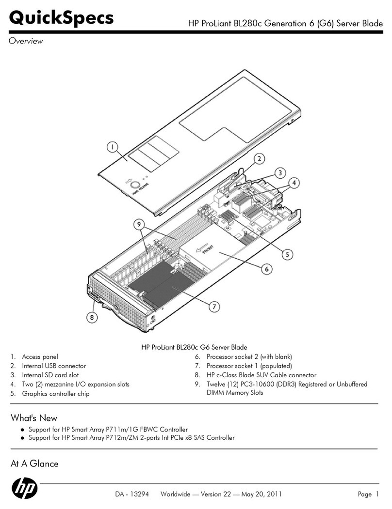
HP
HP ProLiant BL280c Generation 6 (G6) Quickspecs
Dell
Dell PowerEdge 830 Installation and troubleshooting guide
Sun Microsystems
Sun Microsystems Sun Fire T1000 installation guide
