Viper SYNERGIC MIG165 User manual

SYNERGIC
MIG165
Operating Manual | XA-MIG165V
YEA
R
MACHINE
WARRANTY
1
1
YEAR
MACHINE
WARRANTY
10 AMP
TIGMIG MMA
Please read and understand this instruction manual carefully
before the installation and operation of this equipment.
© Xcel-Arc 2022
DC INVERTER WELDER

2
VIPER MIG 165
OPERATING MANUAL
1. Safety 3
2. Machine Features 7
3. Machine Specifications 8
3.1 Technical Data 8
3.2 MIG Specifications 8
3.3 TIG Specifications 8
3.4 STICK Specifications 8
3.5 Size & Weight 8
4. Machine Layout 9
4.1 Front Panel Layout 9
4.2 Rear Panel Layout 9
4.3 Interior Layout 9
5. Control Panel Layout 10
6. Control Panel Operation 10
7. Synergic Settings Operation 11
8. Package Contents 12
9. MIG: Machine Setup (Gasless) 13
10. MIG: Machine Setup (Gas-Shielded) 18
11. MIG: Welding Guide 24
12. MIG: Changing Your Torch Liner 29
13. MIG: Changing Your Torch Liner (Aluminium) 31
14. XA15 BINZEL Style MIG Torch 34
14.1 XA15 MIG Torch Consumables 35
15. MMA: Machine Setup 36
16. MMA: Welding Guide 39
17. TIG: Machine Setup 41
18. TIG: Welding Guide 45
19. Drive Roller Selection 50
20. MIG Troubleshooting 51
21. TIG Troubleshooting 53
22. MMA (STICK) Troubleshooting 55
Contents
REGISTER YOUR MACHINE ONLINE TO RECEIVE AN
ADDITIONAL 6 MONTHS ON YOUR WARRANTY
Visit XcelArc.nz/warranty-registration/ to register your machine.
3
VIPER MIG 165
OPERATING MANUAL
1. Safety
Welding and cutting equipment can be dangerous to both the operator and people in or near the surrounding working
area if the equipment is not correctly operated. Equipment must only be used under the strict and comprehensive
observance of all relevant safety regulations.
Read and understand this instruction manual carefully before the installation and operation of this equipment.
Machine operating safety
• Do not switch the function modes while the machine is operating. Switching of the function modes during welding can
damage the machine. Damage caused in this manner will not be covered under warranty.
• Disconnect the electrode-holder cable from the machine before switching on the machine, to avoid arcing should the
electrode be in contact with the workpiece.
• Operators should be trained and or qualified.
Electric shock: it can kill
• Touching live electrical parts can cause fatal shocks or severe burns. The electrode and work circuit is electrically live
whenever the output is on. The input power circuit and internal machine circuits are also live when power is on. In MIG/
MAG welding, the wire, drive rollers, wire feed housing, and all metal parts touching the welding wire are electrically live.
Incorrectly installed or improperly grounded equipment is dangerous.
• Connect the primary input cable, according to Australian and New Zealand standards and regulations.
• Avoid all contact with live electrical parts of the welding/cutting circuit, electrodes and wires with bare hands.
• The operator must wear dry welding gloves while he/she performs the welding/cutting task.
• The operator should keep the workpiece insulated from himself/herself.
• Keep cords dry, free of oil and grease, and protected from hot metal and sparks.
• Frequently inspect input power cable for wear and tear, replace the cable immediately if damaged, bare wiring is dangerous
and can kill.
• Do not use damaged, undersized, or badly joined cables.
• Do not drape cables over your body.
• We recommend (RCD) safety switch is used with this equipment to detect any leakage of current to earth.
Fumes and gases are dangerous
• Smoke and gas generated while welding or cutting can be harmful to people’s health. Welding produces fumes and gases.
Breathing these fumes and gases can be hazardous to your health.
• Do not breathe the smoke and gas generated while welding or cutting, keep your head out of the fumes.
• Keep the working area well ventilated, use fume extraction or ventilation to remove welding/cutting fumes and gases.
• In confined or heavy fume environments always wear an approved air-supplied respirator.
• Welding/cutting fumes and gases can displace air and lower the oxygen level, causing injury or death. Be sure the breathing
air is safe.
• Do not weld/cut in locations near degreasing, cleaning, or spraying operations. The heat and rays of the arc can react with
vapours to form highly toxic and irritating gases.
• Materials such as galvanised, lead, or cadmium plated steel, containing elements that can give o toxic fumes when welded/
cut. Do not weld/cut these materials unless the area is very well ventilated, and or wearing an air-supplied respirator.
Arc rays: harmful to people’s eyes and skin
• Arc rays from the welding/cutting process produce intense visible and invisible ultraviolet and infrared rays that can burn
eyes and skin.
• Always wear a welding helmet with the correct shade of filter lens and suitable protective clothing, including welding gloves
while the welding/cutting operation is performed.
• Measures should be taken to protect people in or near the surrounding working area. Use protective screens or barriers to
protect others from flash, glare and sparks; warn others not to watch the arc.

4
VIPER MIG 165
OPERATING MANUAL
Fire hazard
• Welding/cutting on closed containers, such as tanks, drums, or pipes, can cause them to explode. Flying sparks from the
welding/cutting arc, hot workpiece, and hot equipment can cause fires and burns. Accidental contact of the electrode
to metal objects can cause sparks, explosion, overheating, or fire. Check and be sure the area is safe before doing any
welding/cutting.
• The welding/cutting sparks & spatter may cause fire, therefore remove any flammable materials well away from the working
area. Cover flammable materials and containers with approved covers if unable to be moved from the welding/cutting area.
• Do not weld/cut on closed containers such as tanks, drums, or pipes, unless they are correctly prepared according to the
required Safety Standards to ensure that flammable or toxic vapours and substances are totally removed, these can cause
an explosion even though the vessel has been “cleaned”. Vent hollow castings or containers before heating, cutting or
welding. They may explode.
• Do not weld/cut where the atmosphere may contain flammable dust, gas, or liquid vapours (such as petrol)
• Have a fire extinguisher nearby and know how to use it. Be alert that welding/cutting sparks and hot materials from welding/
cutting can easily go through small cracks and openings to adjacent areas. Be aware that welding/cutting on a ceiling, floor,
bulkhead, or partition can cause a fire on the hidden side.
Gas cylinders
• Shielding gas cylinders contain gas under high pressure. If damaged, a cylinder can explode. Because gas cylinders usually
are part of the welding/cutting process, be sure to treat them carefully. CYLINDERS can explode if damaged.
• Protect gas cylinders from excessive heat, mechanical shocks, physical damage, slag, open flames, sparks, and arcs.
• Ensure cylinders are held secure and upright to prevent tipping or falling over.
• Never allow the welding/cutting electrode or earth clamp to touch the gas cylinder, do not drape welding cables over the cylinder.
• Never weld/cut on a pressurised gas cylinder, it will explode and kill you.
• Open the cylinder valve slowly and turn your face away from the cylinder outlet valve and gas regulator.
Gas build-up
• The build-up of gas can cause a toxic environment, deplete the oxygen content in the air resulting in death or injury. Many
gases use in welding/cutting are invisible and odourless.
• Shut o shielding gas supply when not in use.
• Always ventilate confined spaces or use approved air-supplied respirator.
Electronic magnetic fields
• MAGNETIC FIELDS can aect Implanted Medical Devices.
• Wearers of Pacemakers and other Implanted Medical Devices should keep away.
• Implanted Medical Device wearers should consult their doctor and the device manufacturer before going near any electric
welding, cutting or heating operation.
Noise can damage hearing
• Noise from some processes or equipment can damage hearing.
• Wear approved ear protection if noise level is high.
Hot parts
• Items being welded/cut generate and hold high heat and can cause severe burns.
• Do not touch hot parts with bare hands. Allow a cooling period before working on the welding/cutting gun. Use insulated
welding gloves and clothing to handle hot parts and prevent burns.

5
VIPER MIG 165
OPERATING MANUAL
Caution
Working environment
• The environment in which this welding/cutting equipment is installed must be free of grinding dust, corrosive chemicals,
flammable gas or materials etc., and at no more than a maximum of 80% humidity.
• When using the machine outdoors, protect the machine from direct sunlight, rainwater and snow, etc.; the temperature
of the working environment should be maintained within -10°C to +40°C.
• Keep this equipment 30cm distant from the wall.
• Ensure the working environment is well ventilated.
Safety tips
• Ventilation: This equipment is small-sized, compact in structure, and of excellent performance in amperage output.
The fan is used to dissipate heat generated by this equipment during the welding/cutting operation. Important: Maintain
good ventilation of the louvres of this equipment. The minimum distance between this equipment and any other objects
in or near the working area should be 30 cm. Good ventilation is of critical importance for the normal performance and
service life of this equipment.
• Thermal Overload Protection: Should the machine be used to an excessive level, or in a high-temperature
environment, poorly ventilated area or if the fan malfunctions the Thermal Overload Switch will be activated, and the
machine will cease to operate. Under this circumstance, leave the machine switched on to keep the built-in fan working
to bring down the temperature inside the equipment. The machine will be ready for use again when the internal
temperature reaches a safe level.
• Over-Voltage Supply: Regarding the power supply voltage range of the machine, please refer to the “Main parameter”
table. This equipment is of automatic voltage compensation, which enables the maintaining of the voltage range within
the given range. In case that the voltage of input power supply amperage exceeds the stipulated value, it is possible to
cause damage to the components of this equipment. Please ensure your primary power supply is correct.
• Do not come into contact with the output terminals while the machine is in operation. An electric shock may occur.
Maintenance
Exposure to extremely dusty, damp, or corrosive air is damaging to the welding/cutting machine. To prevent any possible
failure or fault of this welding/cutting equipment, clean the dust at regular intervals with clean and dry compressed air of
required pressure.
Please note that: lack of maintenance can result in the cancellation of the guarantee; the guarantee of this welding/
cutting equipment will be void if the machine has been modified, attempt to take apart the machine or open the factory-
made sealing of the machine without the consent of an authorized representative of the manufacturer.
Troubleshooting
Caution: Only qualified technicians are authorized to undertake the repair of this welding/cutting equipment. For your
safety and to avoid Electrical Shock, please observe all safety notes and precautions detailed in this manual.

6
VIPER MIG 165
OPERATING MANUAL
Attention! - Check For Gas Leakage
At initial set up and at regular intervals we recommend to check for gas leakage
Recommended procedure is as follows:
1. Connect the regulator and gas hose assembly and tighten all connectors and clamps.
2. Slowly open the cylinder valve.
3. Set the flow rate on the regulator to approximately 8-10 L/min.
4. Close the cylinder valve and pay attention to the needle indicator of the contents pressure gauge on the regulator, if the needle drops away
towards zero there is a gas leak. Sometimes a gas leak can be slow and to identify it will require leaving the gas pressure in the regulator and line
for an extended time period. In this situation it is recommended to open the cylinder valve, set the flow rate to 8-10 L/min, close the cylinder valve
and check after a minimum of 15 minutes.
5. If there is a gas loss then check all connectors and clamps for leakage by brushing or spraying with soapy water, bubbles will appear at the leakage
point.
6. Tighten clamps or fittings to eliminate gas leakage.
IMPORTANT! - We strongly recommend that you check for gas leaks prior to operation of your
machine. We recommend that you close the cylinder valve when the machine is not in use.
Esseti NZ Ltd, authorised representatives or agents of Esseti NZ Ltd will not be liable or responsible for the
loss of any gas.
Warranty
Thank you for your purchase of your Xcel-Arc - VIPER SYNERGIC MIG 165 Welding Machine.
We are proud of our range of plasma cutting and welding equipment that has a proven track record of innovation, performance and reliability.
Our product range represents the latest developments in Inverter technology put together by our professional team of highly skilled engineers. The expertise
gained from our long involvement with inverter technology has proven to be invaluable towards the evolution and future development of our equipment range.
This experience gives us the inside knowledge on what the arc characteristics, performance and interface between man and machine should be.
Within our team are specialist welders that have a proven history of welding knowledge and expertise, giving vital input towards ensuring that our machines
deliver control and performance to the utmost professional level.
We employ an expert team of professional sales, marketing and technical personnel that provide us with market trends, market feedback and customer
comments and requirements. Secondly they provide a customer support service that is second to none, thus ensuring our customers have confidence that they
will be well satisfied both now and in the future.
Xcel-Arc welders and plasma cutters are manufactured to be compliant with - AS/NZ 60974-1, guaranteeing you electrical safety and performance.
• 2 Year from date of purchase.
• ESSETI New Zealand Limited warranties all goods as specified by the manufacturer of those goods.
• This Warranty does not cover freight or goods that have been interfered with.
• All goods in question must be repaired by an authorised repair agent as appointed by this company.
• Warranty does not cover abuse, misuse, accident, theft, general wear and tear.
• New product will not be supplied unless ESSETI New Zealand Limited has inspected product returned for
warranty and agrees to replace product.
• Product will only be replaced if repair is not possible
• Please view full Warranty term and conditions at www.XcelArc.nz/warranty-terms
WARRANTY TERMS
WARRANTY TERMS

7
VIPER MIG 165
OPERATING MANUAL
2. Machine Features
VIPER SYNERGIC MIG 165
Synergic MIG Control
The clever Synergic MIG control takes the guesswork out
of your settings. Simply select your wire size and wire type,
and adjust your amperage to suit your work piece. The
program works with mild steel, stainless steel, flux-cored
and aluminium wires.
Gas & Gasless MIG
This machine supports both gas-shielded MIG and gasless
MIG wire, meaning you can easily run mild steel, stainless
steel & flux-cored MIG wire.
Multi-Process Welding
This three-in-one machine, lets you perform MIG, TIG and
STICK welding all on one machine. There is no need to
swap between machines, saving you time and setup.
10A Plug
A 10 AMP power plug can be used on any domestic outlet.
It’s perfect for the DIY home handyman or the professional
welder looking for a machine that can be used almost
anywhere.
Lightweight & Portable
Weighing just 9.8kg, the VIPER MIG 165 is ready to go
anywhere you need it.
8
VIPER MIG 165
OPERATING MANUAL
3. Machine Specifications
VIPER SYNERGIC MIG 165
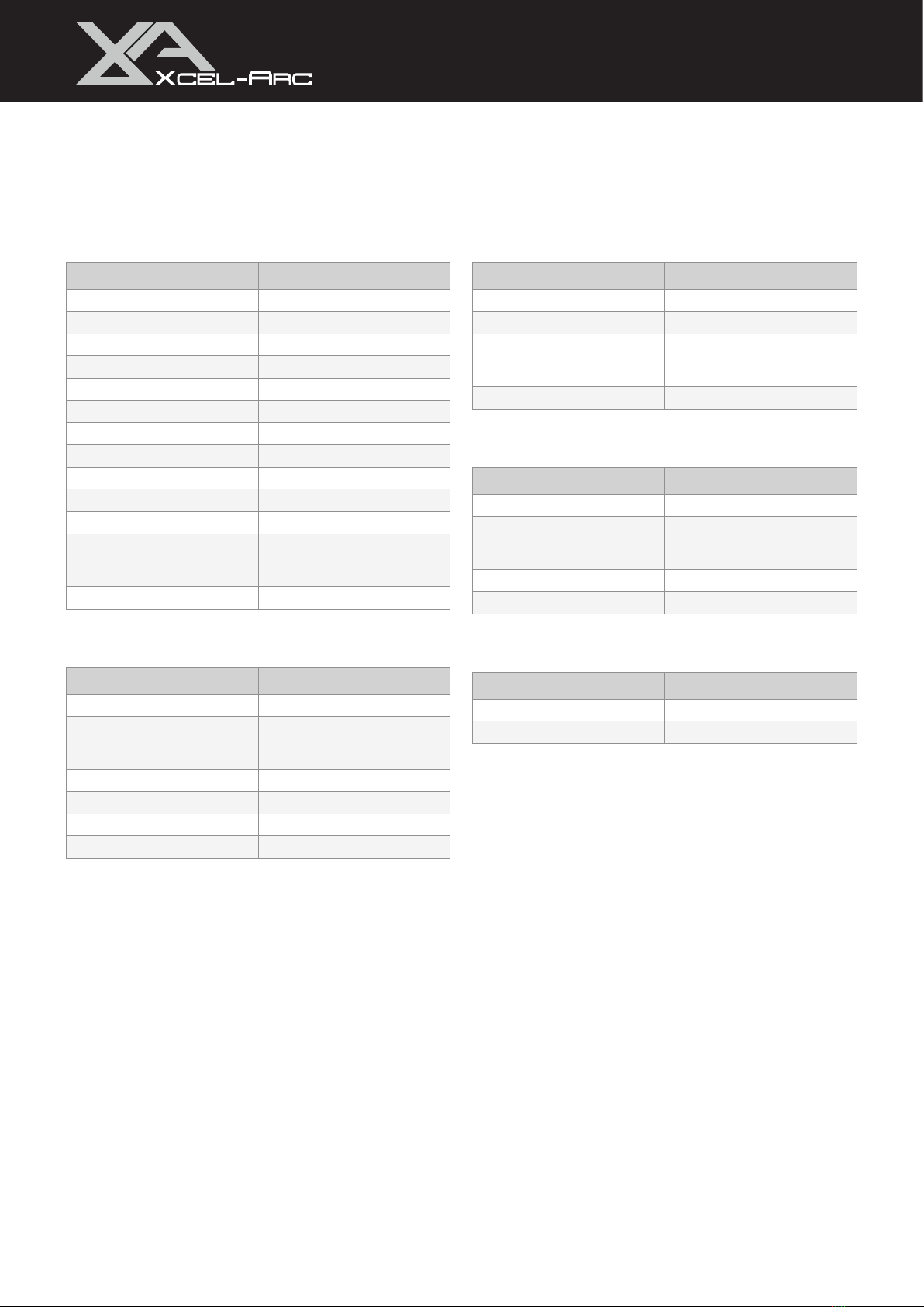
3.1 Technical Data
Parameter Values
SKU XA-MIG165V
Primary Input Voltage 230V Single Phase
Supply Plug 10 AMP
Ie (A) 10.0
Rated Output 30A/15.5V - 165A/22.3V
No Load Voltage (V) 64
Protection Class IP21S
Insulation Class H
Minimum Generator (kVA) 9.0
Dinse Connector 35/50
Standard AS/NZ60974-1
Welds Mild Steel, Stainless Steel, Cast
Iron, Silicon Bronze, Aluminium,
Copper
Warranty (Years) 2
3.2 MIG Specifications
Parameter Values
MIG Welding Current Range 30-165A
MIG Duty Cycle @ 40°C 10% @ 165A
60% @ 68A
100% @ 52A
MIG Wire Size Range 0.6-0.9mm
MIG Wire Spool Size 1kg / 5kg
MIG Welding Thickness Range 1-8mm
Drive Roller SIze 30/10
3.3 TIG Specifications
Parameter Values
TIG Function Type DC Lift Arc
TIG Welding Current Range 20-160A
TIG Duty Cycle @ 40°C 10% @ 160A
60% @ 65A
100% @ 50A
TIG Welding Thickness Range 1-6mm
3.4 STICK Specifications
Parameter Values
STICK Welding Current Range 20-140A
STICK Duty Cycle @ 40°C 10% @ 140A
60% @ 58A
100% @ 45A
STICK Electrode Range 2.5-3.2mm
STICK Welding Thickness Range 2-8mm
3.5 Size & Weight
Parameter Values
Dimensions (mm) 513x206x391mm
Weight (kg) 9.8kg

9
VIPER MIG 165
OPERATING MANUAL
4. Machine Layout
4.1 Front Panel Layout
1. Weld Parameters Panel
2. Euro Connection
3. “+” Output Terminal
4. Polarity Cable
5. “-” Output Terminal
4.2 Rear Panel Layout
6. On/O Switch
7. Input Power Cord
8. Gas Inlet
9. Fan
4.3 Interior Layout
10. Wire Feeding Spool Holder
11. Wire Feeder
ON
OFF
GAS IN
1
2
34
5
7
8
6
9
10 11

10
VIPER MIG 165
OPERATING MANUAL
5. Control Panel Layout
1. Voltage Display
2. Wire Speed / Amperage Display
3. Synergic Selector
4. MIG/TIG/STICK Selector
5. Torch Mode Selector
6. Wire Size Selector
7. Wire Type Selector
8. Voltage Knob
9. Wire Speed / Amperage Knob
10. Inductance Knob
6. Control Panel Operation
6.1 Voltage Adjustment Knob
Provides digital adjustment of voltage in MIG and MIG Synergic.
• Turn the knob to increase or decrease the desired value displayed on the
LED display.
6.2 Amperage / Wire Speed Adjustment Knob
Provides digital adjustment of wire speed in MIG, and adjustment of amperage in MIG
Synergic, TIG and STICK.
• Turn the knob to increase or decrease the desired value displayed on the
LED display.
1 2 3
4 5 6 7
8 9 10

11
VIPER MIG 165
OPERATING MANUAL
6.4 Weld Mode Selector
Enables selection of required welding mode:
• MMA
• TIG
• MIG
6.5 MIG Torch Mode Selector
Controls the on/o cycle of the machine using the torch trigger while incorporating the
weld program parameters:
• 2T (two times) (1) Pull the trigger and hold it in, the welding will start and remain welding
while you hold the trigger on.
(2) Release the trigger and the welding stops.
• 4T (four times) (1) Pull the trigger and (2) release, the welding will start and continue weld.
(3) Pull the trigger and (4) release, the welding will stop.
6.3 Inductance Adjustment Knob
Inductance is what allows you to change the frequency of your short circuit – how often
the wire touches the joint in the circuit’s cycle.
The lower your inductance setting, the more frequently your weld will short circuit. Less metal is
being added, so the bead is narrower and freezes faster. A low inductance is generally used on
thinner metals when you want to avoid burning through.
The higher your inductance setting, the less frequently your weld will short circuit. If you set the
machine to 100% inductance, you would get a soft, fluid weld pool that wets out well.
7. Synergic Settings Operation
7.1 Synergic Selector
Activate Synergic mode while MIG is selected.
7.2 Wire Size Selector
Enables selection of MIG wire diameter in Synergic mode.
7.3 Wire Type Selector
Enables selection of MIG wire type in Synergic mode.

12
VIPER MIG 165
OPERATING MANUAL
8. Package Contents
VIPER Synergic MIG 165
Drive Rollers
3m XA15 MIG Torch
Electrode Holder
3m 300 AMP Earth Clamp
Twin Gauge Argon Regulator
10A Plug (Fitted)
XCEL-GAS
XCEL-GAS
X
CEL-
G
AS
XCEL-GAS
XCEL-GAS
X
CEL-
G
AS
1 x 0.8-0.9mm “V GROOVE” 30/10
1 x 0.8-0.9mm “F GROOVE” 30/10
1 x 0.9-1.0mm “U GROOVE” 30/10
13
VIPER MIG 165
OPERATING MANUAL
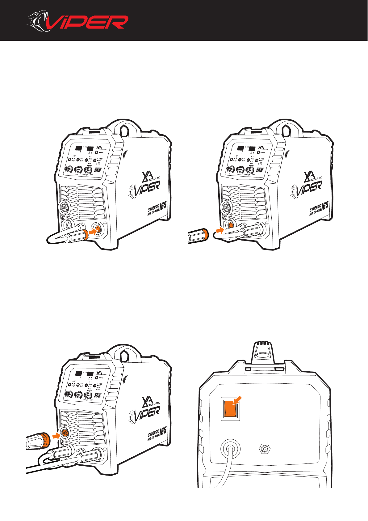
9. MIG: Machine Setup (Gasless)
ON
OFF
GAS IN
1. Connect the polarity cable to the negative (-) dinse
connection, twist to lock in place.
2. Connect the earth clamp to the positive (+) dinse
connection, twist to lock in place.
3. Connect the MIG torch to the Euro connection, and
twist end to secure in place.
4. Connect the plug into a 10 AMP socket, then switch the
machine ON.
14
VIPER MIG 165
OPERATING MANUAL
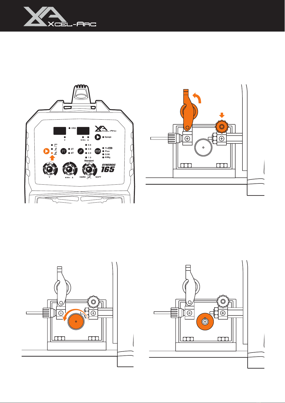
MIG: Machine Setup (Gasless)
5. Select MIG from the MIG/TIG/MMA selector. 6. Pull down the roller tension knob to release the wire
drive.
7. Unscrew the roller cap. 8. Ensure you have a Knurled (F Groove) drive roller
installed. If not, fit correct roller and replace the roller
cover.
15
VIPER MIG 165
OPERATING MANUAL
MIG: Machine Setup (Gasless)
Burnback Adjustment
SPOOL GUN
STANDARD
Burnback Adjustment
Burnback Adjustment
SPOOL GUN
STANDARD
Burnback Adjustment
Burnback Adjustment
Burnback Adjustment
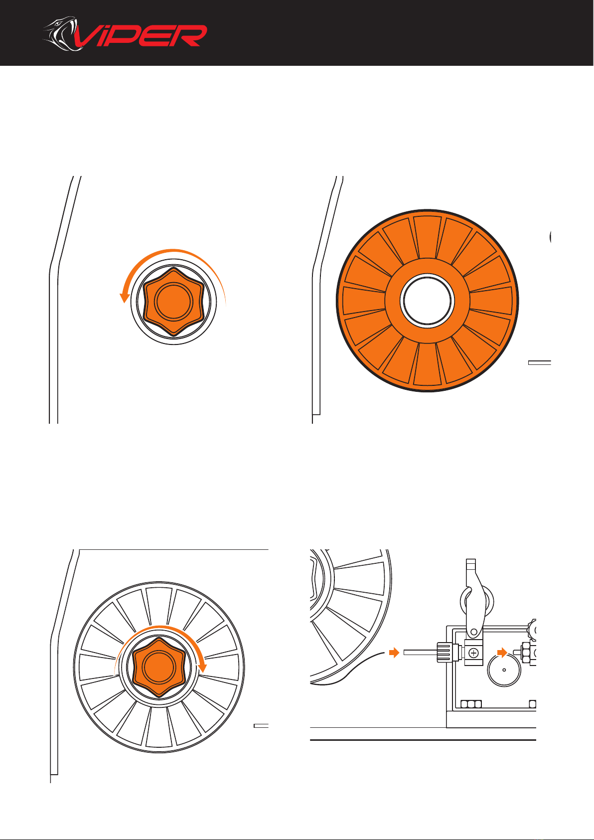
9. Unscrew spool retaining nut. 10. Place 5kg wire spool onto the spool holder. For 1kg
spool, see step 20.
11. Tighten spool retaining nut. 12. Feed wire through the inlet guide tube to the outlet
guide tube. Ensure that the wire passes through the
roller.

16
VIPER MIG 165
OPERATING MANUAL
13. Lift roller tension knob to lock wire in place. Twist to
tighten.
14. Remove front end consumables from the MIG torch.
15. Hold the torch trigger to feed wire through to the torch.
If the wire slips or stops you will need to adjust the
roller tension knob.
16. Replace front end consumables on the MIG torch.
MIG: Machine Setup (Gasless)

17
VIPER MIG 165
OPERATING MANUAL
17. For Synergic MIG operation, select your wire size and
type. Adjust the amperage dial up or down according
to your material thickness.
For Standard MIG operation adjust the voltage and
wire feed speed according to your material thickness.
18. Connect earth clamp to your workpiece.
19. Line up the torch with your workpiece, then simply
pull the trigger to initiate the weld. For gasless MIG,
the drag method is recommended for optimum weld
quality. Release trigger to end the weld.
MIG: Machine Setup (Gasless)

18
VIPER MIG 165
OPERATING MANUAL
10. MIG: Machine Setup (Gas-Shielded)
ON
OFF
GAS IN
1. Connect the polarity cable to the positive (+) dinse
connection, twist to lock in place.
2. Connect the earth clamp to the negative (-) dinse
connection, twist to lock in place.
3. Connect the MIG torch to the Euro connection, and
twist end to secure in place.
4. Connect the plug into a 10 AMP socket, then switch the
machine ON.

19
VIPER MIG 165
OPERATING MANUAL
5. Select MIG from the MIG/TIG/MMA selector. 6. Pull down the roller tension knob to release the wire
drive.
7. Unscrew the roller cap. 8. Ensure you have a V Groove drive roller installed. If not,
fit correct roller and replace the roller cover.
MIG: Machine Setup (Gas-Shielded)
20
VIPER MIG 165
OPERATING MANUAL
Burnback Adjustment
SPOOL GUN
STANDARD
Burnback Adjustment
Burnback Adjustment
SPOOL GUN
STANDARD
Burnback Adjustment
Burnback Adjustment
Burnback Adjustment
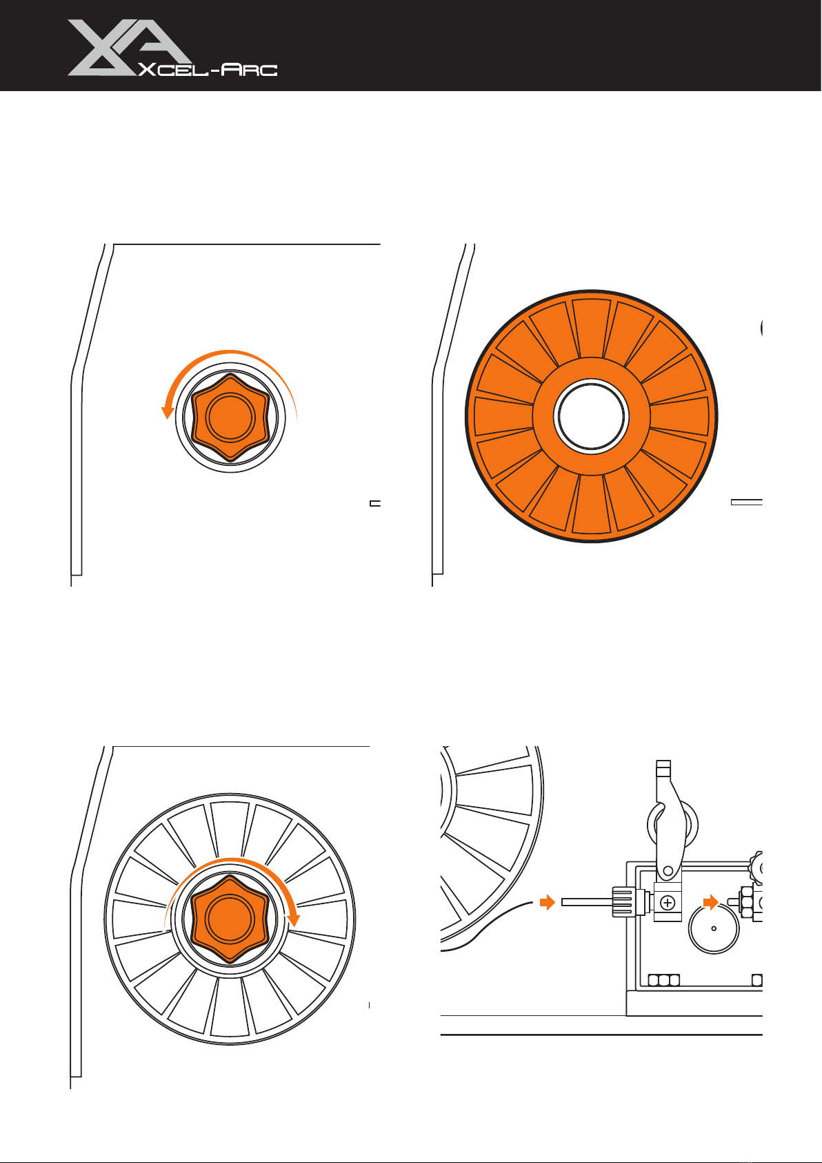
9. Unscrew spool retaining nut. 10. Place 5kg wire spool onto the spool holder.
11. Tighten spool retaining nut. 12. Feed wire through the inlet guide tube to the outlet
guide tube. Ensure that the wire passes through the
roller.
MIG: Machine Setup (Gas-Shielded)
This manual suits for next models
1
Table of contents
Other Viper Welding System manuals


Popular Welding System manuals by other brands

Lincoln Electric
Lincoln Electric POWER WAVE 405M Service manual

Bestarc
Bestarc BTC450NP manual

ESAB
ESAB Aristo WeldCloud Mig U5000i instruction manual

Cebora
Cebora PLASMA PROF 123 instruction manual

Hobart Welders
Hobart Welders IronMan 250 owner's manual

Lincoln Electric
Lincoln Electric Power Wave AC/DC 1000 MC04-216 Technical specifications


Miller Electric
Miller Electric AUTO ARC AATC-150 owner's manual

Lincoln Electric
Lincoln Electric POWER WAVE IM986 Operator's manual

Miller
Miller Multimatic 200 owner's manual

Weldclass
Weldclass WeldForce WF-255MST operating instructions

Clarke
Clarke Weld 215TE Operating & maintenance instructions

Kemppi
Kemppi X3 operating manual