Viscount C-440 User manual

Classic Keyboard
Organ
C-44f).
C-44ti.
C-44ti~.
C-44tir=
•
C-tif)ti.
441.
titif).
tiSf).tJSti
Service Notes
First Edition
Rodgers Instrument Corporation
1300 N. E.
25th
Avenue
Hillsboro,
Oregon
97124
U.S.A
PIN 1905-064
Contents
WARNING .•.•.••.••••...•••...•••.•••...•...........••.•.•.......•.•.••.••...............•••........••••....•••••••.•.... 4
Model
Specifications••••••••••.•••••••••......•.............•..••.•.....•••.•.••........••..••..•••.•••••...•••••••••.......••••••....4
Notes •••....•••••...••....•••.•..•........•......................•.•...................•..........••••••......................• 4
Model
Block
Diagrams
••••••••.•.•••••......•........•.•.....•.•......••..••••......••••••..•.•.••••.....••••••••••.•...•...•••••...4
Schematics •••••••••••••••••••••••••..•.••••..•....••..•..........•••••....................••••..........•••..........••.••......••.•••.....4
Firmware
SystemBlock
Diagram
••..••.....•••.••....•••••..••...••••...••.............•••.•••....••••••...•.••••...........•••5
5215-304 Digital Voice
Module
••••...•....••.•..•....•.•....•.•.•.•....................•••.........•.••..•••••••...........••••5
7117441000 Digital
Reverb
Board
.........•••••............•..••••••....•.......•....••.•.......••••••.•..•••............••.•5
Hardware-
Wire
Trap
Connectors
..•......••.•.........•..•••••.•...............•...•...........••••.......•••...........••••5
External
Speaker
Terminal
Connector
Assignments 550, 580, 685 ..........................................6
External
AmplifierConnections 550, 580, 685 •••.••............•.•..•••...........•............••..........•.•••.....6
Printed
Circuit
Board
Assembly
Chart
.................................................................... 7
PCB
Placement
on
Key
deck
••••.•••.......................•..................•..•.............•.•..........••..•••..•.••.••....•.8
ApplicationNotes .....•.....•••........................................................................................ 9
Adding
a
Cable
Routing
Cover
to
the
550, 580,
or
685
Organ
Back
........................................9
550/580•.•••.....••••..•.•••••••••••••••••••••....•.......•...•..........•....•.••••.•..............•...........•••.•••••••••........••..•••9
685 ············-································································································································9
Two
piececonsoles•...•••••••••.•••••••••..................••....•....•..•••.••••........•......•.•••.......•..•.•••••••........•..••11
AssemblyInstructions...........•.....................•..•....................•.........•....................••.....
11
Opening
Console••••....•.•••.•...•...•••.......••.•..........••.••.•.•...................•..••......••••..•.......•.•.•.•••..•...••.•
13
Keyboard andPistonRailSer-vicing ....................................................................... 14
Keyboard
and
PistonRailAssembly/disassembly••••••••.•...•....•.•...........••.••••••.•..•........•••••......... 14
Detaching
keyboard
from
Circuit
Board
.......•..•....................•..............••..........•••........••...........14
Individual
Key
Service •.•••••••.••.••••.........................................................................•....•...........•16
Key
removal•••••••••••••.••..•....••••.•..•.....•...............•...•...................................................................16
Key
:Installation .••.......••••••••••.•..•.•....................•..•...........•........•......................•...••••.•.............••18
Tilt
Tab
Lamp
and
SwitchDis-assembly/Assembly.................................................................20
Tilt
Tab
Service••••.................................................................................................... 20
Removing
and
ReplacingTilt
Tab
....................................••..•.............•.............•........•.............21
Tilt
Tab
Layout
-Model Notes.............................................•................................•.••.............21
Test
Mode
Display•.••..•.•...••.••.....•.....•..............•.•••...•....•..........................••.••••.•••......••...•.....•.••21
Factory
Adjustment
for
Expressionand Tremulants.............................................. 24
Miscellaneous
Parts
....................................................................•............................ 25
Page
2 Rodgers Instrument Corporation

Appendixes
Block
Diagrams
.•••••..•..•••.••........•...................................•...........•.•••.•••••....••••••.••.•..... A
Signal Flow
Diagram
•.•.••...•••....•......•...•.....•.••••.••.•.••..•••..•••........••............•......•••••..........•••••• A-1
4003-550
Firmware
Diagram....•................•..••••.•...•.....•...•.•.....••.•......•....•.•.••..•••.......••....••••. A-2
C-440, C-445, C-505, 441 Block Diagram .•..•••...•..•..••••...••.........•......•......•......••••..............•• A-3
550 Block
Diagram
••.......•...••••...••...........•...•••••..•...•...........••........••.....•...•.•••••..•.•................•. A-4
580 Block
Diagram
•••••••••••.••..••.•••••..•.•.......••••••••••••••••••••.........•••.............••...•••••••••........•••••.•.
A-5
685 Block
Diagram
•••••••••••..•••••..•••••.•••.•.....•.•••••••••••••••••••••.......••.•.....•.....•••...••••••••......••.•••••••
A-6
5215-304 Digital Voice Module Block Diagram
•••••••••..•••......•••.......••.....••••.••••••••........•••••...
A-7
5235-300
Head
phone
Amp
...•.................................•••.........•.....•..•••................•..........B
5222-300
Main
1/0
C-Series •.................•..••••••••..••................•.................................• C
5222-301
Main
1/0
............•••......................................•.•......•.....••...••••.........•............ C
5218-301
Output
Preamp
4-Ch .............•..••.•..•...•....•.••.......•••.•.••••••••.•••...•••••........... D
5208-300 Main
Power
Supply.•....................•..••........................................................E
5256-300
Main
Power
Supply 580/685 ...............................................•..................... F
525~-3()()
Po~er
Amp
Suppl~
:;so
............................................................................
~
525~-301
Power
Amp
Supply 685............................................................................ ~
5257-302
Power
Amp
Supply 550
•••••••.••••.•••••••••••••••••.•••••••••••••••••••••••••••••••••••••••••••••
~
5249-300
Reed
Switch
Pedal
Encoder
..................................................................... H
5260-300
Speaker
Switch 580 ..................................•...............•.....••........•...........•.....I
5200-302 Stereo
Amp
Module .................................................••....•.......................... J
5200-303 Stereo
Amp
Module 580/685.................................•.............••..................•• J
5205-300
Tilt
Tab Switch
Board
..................
~
...........................•...••.....•..........•..•...... K
5206-3()()
Tilt
Tal>
Encoder
...................................................................................... K
5253-3()0
User
1/0
Board
..........................................................................................L
5236-3()1
Back
Panel
Board
.........................................................•...........................M
Miscellaneous Sub-assemblies .•...........................•........................•.....•.................... N
AC-Line Cables C-440, C-445, C-505, 441 •.••.••••••.••••••.......•.•................••.....•................•...• N-1
AC-Line Cables 550, 580, 685 ....•.•..•...•....•........•..••...•••..........•..•....•••......•......•••.........•••••••.. N-2
Classic
Keyboard
Piston Rails••.••...•.......•.•••••••••••••.•..•••...•..•........•••.••••••....••••.•....•.••••..•....... N-3
Transposerffuner
Assembies ............................................................................................... N-4
Base
Harness
C-440,441 ...................................................................................................... N-5
Base
Harness
C-445, C-505 ...•..........•.......................................................................••.•••...•. N-6
Kneeboard
Harness 550....................................................................................................•.• N-7
Kneeboard
Harness 580..................................................................................................•.... N-8
Kneeboard
Harness
685................................................................................................•••••.. N-8
Classic Keyboard Organ Service Notes
Page3
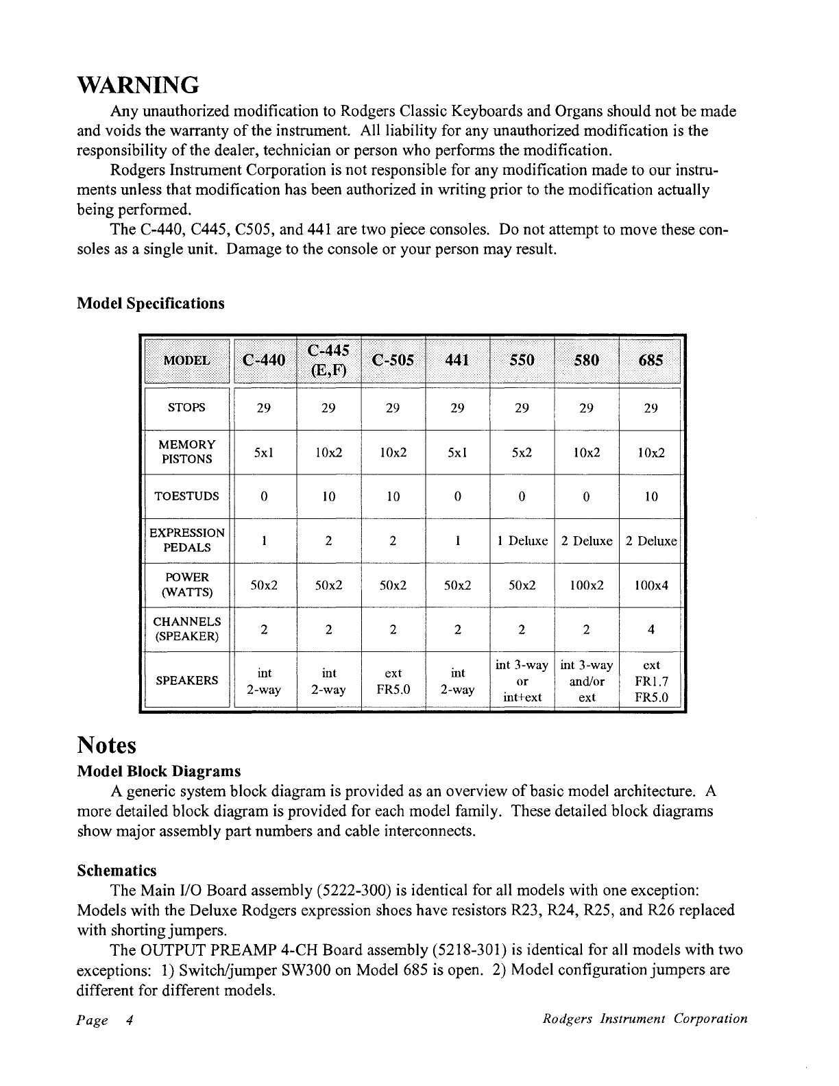
WARNING
Any unauthorized modification to Rodgers Classic Keyboards and Organs should not
be
made
and voids the warranty
of
the instrument. All liability for any unauthorized modification is the
responsibility
of
the dealer, technician or person who performs the modification.
Rodgers Instrument Corporation is not responsible for any modification made to our instru-
ments unless that modification has been authorized in writing prior to the modification actually
being performed.
The C-440, C445, C505, and 441 are two piece consoles. Do not attempt to move these con-
soles as a single unit. Damage to the console or your person may result.
Model Specifications
Notes
STOPS
MEMORY
PISTONS
TOESTUDS
EXPRESSION
PEDALS
POWER
(WATTS)
CHANNELS
(SPEAKER)
SPEAKERS
Model Block Diagrams
29
5xl
0
50x2
2
int
2-way
29
10x2
10
2
50x2
2
int
2-way
29
10x2
10
2
50x2
2
ext
FR5.0
29
5xl
0
50x2
2
int
2-way
29 29 29
5x2
10x2
10x2
0 0
10
I Deluxe 2 Deluxe 2 Deluxe
50x2
100x2
2 2
int 3-way int 3-way
or and/or
int+ext ext
100x4
4
ext
FRI.7
FR5.0
A generic system block diagram is provided as an overview
of
basic model architecture. A
more detailed block diagram is provided for each model family. These detailed block diagrams
show major assembly part numbers and cable interconnects.
Schematics
The Main
I/0
Board assembly (5222-300) is identical for all models with one exception:
Models with the Deluxe Rodgers expression shoes have resistors R23, R24, R25, and R26 replaced
with shortingjumpers.
The OUTPUT PREAMP 4-CH Board assembly (5218-301) is identical for all models with two
exceptions:
1)
Switch/jumper SW300
on
Model 685 is open. 2) Model configurationjumpers are
different for different models.
Page 4 Rodgers Instrument Corporation

Firmware System Block Diagram
A Firmware System Block Diagram is provided to aid in the understanding
of
instrument
operation.
It
is presented in a similar form to
an
electronic schematic diagram. It is for reference
only and represents the state
of
Rodgers part number 4003-550.-
The C-440, C-445, and C-505 are manufactured with firmware named 4003-103. The 441,
550, 580, and 685 are shipped with firmware named 4003-550. 4003-550 is an enhanced version
of
4003-103 and will work in all models. Model configuration jumpers are located on the OUTPUT
PREAMP 4-CH Board assembly (5218-301). The firmware uses these jumpers and other tests to
determine model number.
The C-445E firmware is configured for different sounds and therefore is not compatable with
the other organs.
5215-304 Digital Voice Module
The only parts on this module which are field servicable are the Program and Sample ROMs.
7117441000 Digital Reverb Board
The digital Reverb Board is not field serviceable but rather field replaceable.
Hardware -Wire Trap Connectors
Many
of
the interconnect systems in these models use a connector many technicians may not be
familiar with. These connectors allow special Top Coated ( looks like tinned ) ribbon cable to be
plugged directly into the connector. The wire is locked in place unless the connector release latch is
depressed. This connector is very cost effective and reliable. Caution must be used when inserting
the cable into the connector. Make sure that all wires are correctly aligned with their respective
holes. Pay particular attention that pin one
on
the wire (marked with a blue stripe) is inserted into
pin one
of
the connector (marked on the PCB silkscreen with a triangle). Depress the release bar
when inserting or releasing the cable.
Classic Keyboard
Organ
Service Notes Page 5

External Speaker Terminal Connector Assignments 550, 580, 685
550*, 580
685
CHANNEL 1- Swell, Great & Pedal -RIGHT
CHANNEL 2 - Swell, great & Pedal -LEFT
CHANNEL 1
-Swell-
RIGHT
CHANNEL
2-
Swell
-LEFT
CHANNEL 3
-Great
& Pedal
-RIGHT
CHANNEL 4
-Great
& Pedal
-LEFT
External
Amplifier Connections 550, 580, 685
550,
580
685
P-5 Connector (DB-9)
PIN 1 - Ground
PIN 2 - Channel 2
PIN 3 - Channel 1
PIN
6-
Relay Ref.
(OV.)
PIN
7-
Relay+
(+12V.)
P-5 Connector (DB-9)
PIN 1 - Ground
PIN 2 - Channel 2
PIN 3 - Channel 1
PIN 4 - Channel 4
PIN 5 - Channel 3
PIN 6
-Relay
Ref.
(OV.)
PIN7-Relay+
(+12V.)
P-6 Connector (DB-9)
PIN 1 - Ground
PIN 2 - Channel 4
PIN 3 - Channel 3
PIN
6-
Relay Ref.
(OV.)
PIN
7-
Relay+
(+12V)
*Note,
early production models did not have speaker terminal blocks. Contact Classic Key-
board Technical Services
if
this feature is required.
Page
6 Rodgers Instrument Corporation
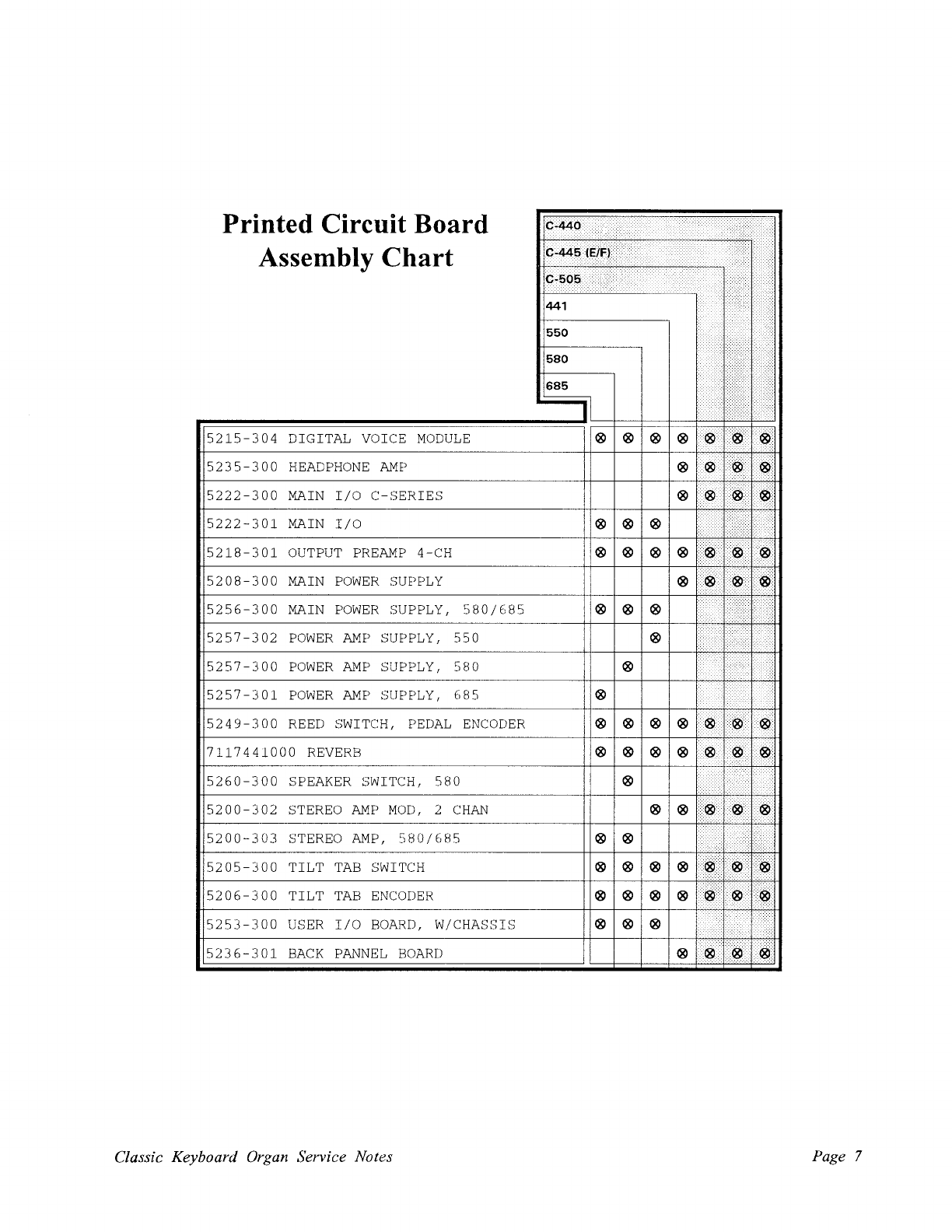
Printed Circuit Board
Assembly Chart
5215-304
DIGITAL VOICE
MODULE
5235-300
HEADPHONE
AMP
5222-300
MAIN
I/0
C-SERIES
5222-301
MAIN
I/0
5218-301
OUTPUT
PREAMP
4-CH
5208-300
MAIN
POWER
SUPPLY
5256-300
MAIN
POWER
SUPPLY,
580/685
5257-302
POWER
AMP
SUPPLY,
550
5257-300
POWER
AMP
SUPPLY,
580
5257-301
POWER
AMP
SUPPLY,
685
5249-300
REED
SWITCH,
PEDAL
ENCODER
7117441000
REVERB
5260-300
SPEAKER SWITCH,
580
5200-302
STEREO
AMP
MOD,
2
CHAN
5200-303
STEREO
AMP,
580/685
5205-300
TILT
TAB
SWITCH
5206-300
TILT
TAB
ENCODER
5253-300
USER
I/0
BOARD,
W/CHASSIS
5236-301
BACK
PANNEL
BOARD
Classic Keyboard Organ Service Notes
® ® ®
® ® ®
® ® ®
®
®
®
® ® ®
® ® ®
®
® ®
® ® ®
® ® ®
® ® ®
Page 7
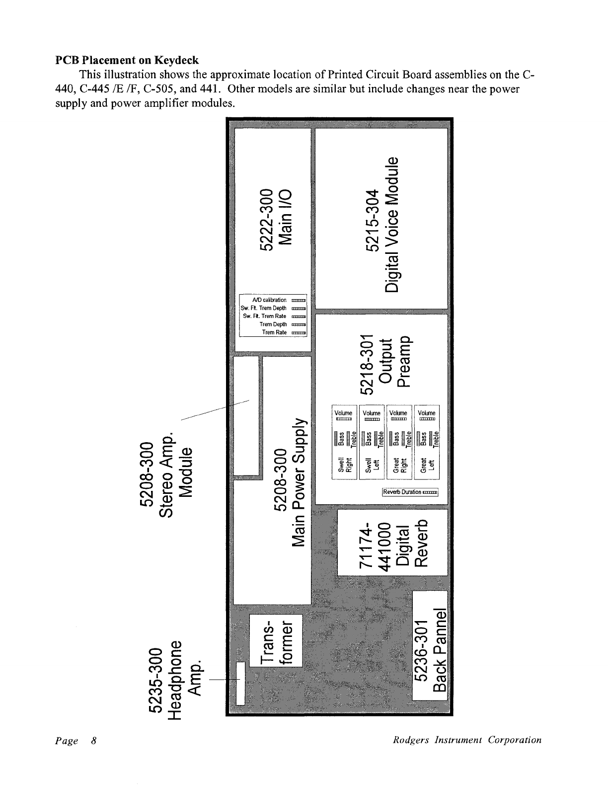
PCB
Placement
on
Keydeck
This illustration shows the approximate location
of
Printed Circuit Board assemblies on the C-
440,
C-445/E
IF, C-505, and 441. Other models are similar but include changes near the power
supply and power amplifier modules.
Page 8
0~
0 0 .
('t)
...c
0.
I
0.
E
I.()"'C<(
('t)Ct'S
NQ)
I.OI
oo
0-....
('t)-
•c
N·-
NctS
N:::E
lO
AID
caibration
amm
SW.
R.
Trem
Depth
amm
llllllllllllllllllllllllllllllllllllllllllllllllllllllllllllllllllllllllllllllllllllllllllllllllllllll
SW.
Fl.
Trem
Rate
IIIIIID
Trem
Depth
amm
Trem
Rate
a:mm
~
c..
c..
o::s
ocn
('t)
~
IQ)
oo:s:
00
~a.
c
ctS
:::E
Voi!Jne
Volume
Volume Volume
IIIIIlD
1IIIIIID
IIIIIIID
m
Rodgers Instrument Corporation

Application Notes
Adding a Cable Routing Cover to
the
550, 580,
or
685
Organ
Back
The
new
550, 580 and 685 Classic Keyboard Organs have been designed so that audio and
MIDI cables can
be
routed through the organ console back and out the organ kneeboard, rather than
leaving the cables draped over the side
of
the organ.
To
do this, Rodgers is using a device called a
Cable Routing Cover.
The
Cable Routing Cover has been factory installed on the organ kneeboard,
but
must
be
installed in the organ back
by
the Dealer
or
technician, should the end-user elect to use this feature.
An alternative to adding the Cable Routing Cover to the back is to use the cable notches located on
both the left and right lower sides
of
the back.
550/580
These instruments have fabric covered backs, and have two cutouts hidden under the fabric for
the Cable Routing Cover. they are positioned above and below the deck, and are located along the
upperright side
of
the back.
685
1.
Remove the back from the organ.
2. Determine which one
of
the two openings is most appropriate to use.
3. Using the tip
of
a
hot
electric soldering pencil (25 watts is perfect), push it through the
fabric along the inside edge
of
the opening ,using the opening as a template, and carefully
"cut" the fabric from the inside
of
the opening.
The
soldering pencil is used to provide a
clean "cut", and to seal the ends
of
the fabric, which prevents unraveling. See diagram
1.
4. Remove the Cap
of
the Cable Routing Cover
by
pulling
it
from the Flange .
5. Press the Flange into the opening from the inside surface (the painted surface, not the
fabric-covered surface) with a smooth, even pressure. This is a tight friction fit, and
generally
doesn't
require adhesives to hold
it
in place. See diagram 2.
6.
Hold
the Cap in your hand and gently slide the door down to unlatch it. When the door is
unlatched, swing
it
in to expose the cable opening. See diagram 3.
7. Route the cables through the organ, make the cable connections, and press the Caps into
the Flanges.
These instruments have wooden backs, and require the Dealer
or
technician to drill a hole in
the back to install the Cable Routing Cover.
1.
Remove the back from the organ.
2. Determine the most appropriate place to drill the hole.
3. Carefully drill a 1-3/4" diameter hole from the outside surface.
4. Remove the Cap
of
the Cable Routing Cover
by
pulling
it
from the Flange .
5. Press the Flange into the hole from the inside surface with a smooth, even pressure. This is
a tight friction fit, and generally doesn't require adhesives to hold
it
in place. See diagram
2.
6. Hold the Cap in your hand and gently slide the door down to unlatch it. When the door is
unlatched, swing
it
in to expose the cable opening. See diagram 3.
7. Route the cables through the organ, make the cable connections, and press the Caps into
the Flanges.
Classic Keyboard
Organ
Service Notes Page 9
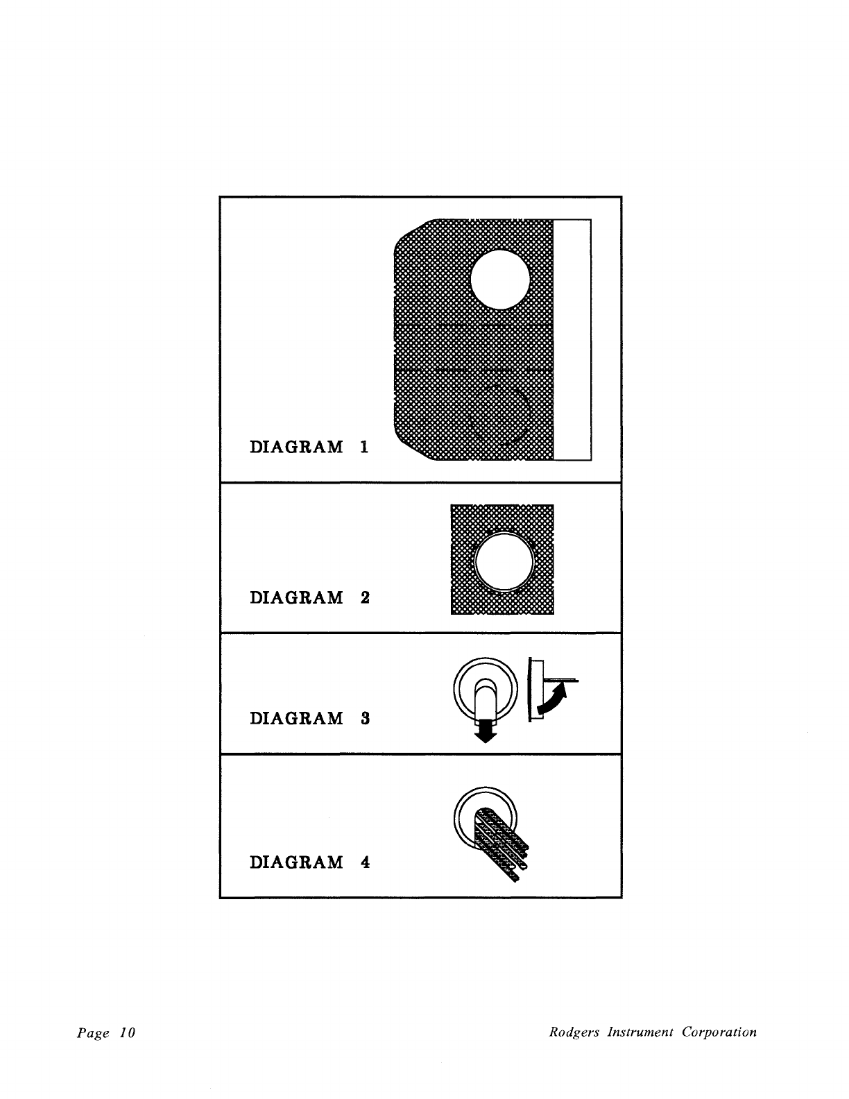
DIAGRAM 1
DIAGRAM 2
DIAGRAM 3
DIAGRAM 4
Page
10
Rodgers Instrument Corporation
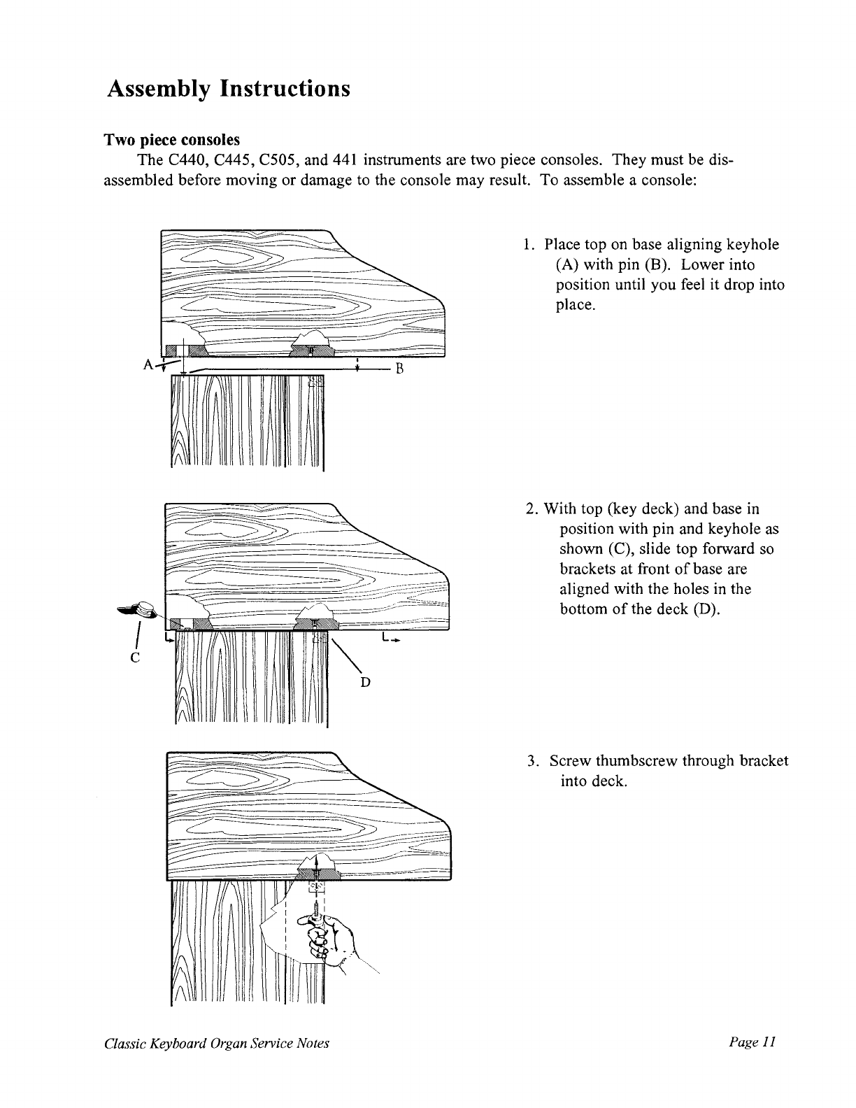
Assembly Instructions
Two piece consoles
The C440, C445, C505, and
441
instruments are two piece consoles. They must be dis-
assembled before moving or damage to the console may result. To assemble a console:
-:::-
:::::--...~
~
-=-......
~
~-
~
==-~
~
<
'\
/
I~
A..;-
! B
~
~
~
D
Classic Keyboard
Organ
Service Notes
1.
Place top on base aligning keyhole
(A) with pin (B). Lower into
position until you feel it drop into
place.
2.
With top (key deck) and base in
position with pin and keyhole as
shown (C), slide top forward so
brackets at front
of
base are
aligned with the holes in the
bottom
of
the deck (D).
3.
Screw thumbscrew through bracket
into deck.
Page
11
Page
12
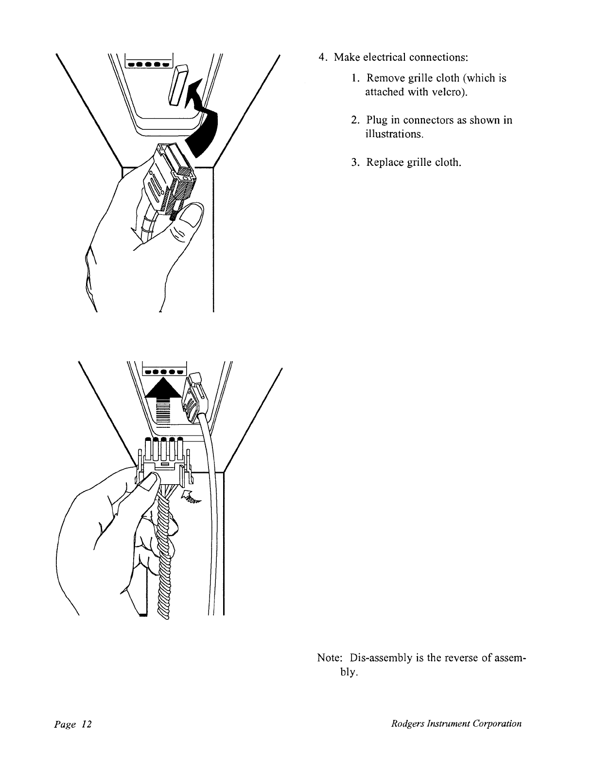
4. Make electrical connections:
1.
Remove grille cloth (which is
attached with velcro
).
2.
Plug in connectors as shown in
illustrations.
3.
Replace grille cloth.
Note: Dis-assembly is the reverse
of
assem-
bly.
Rodgers Instrument Corporation
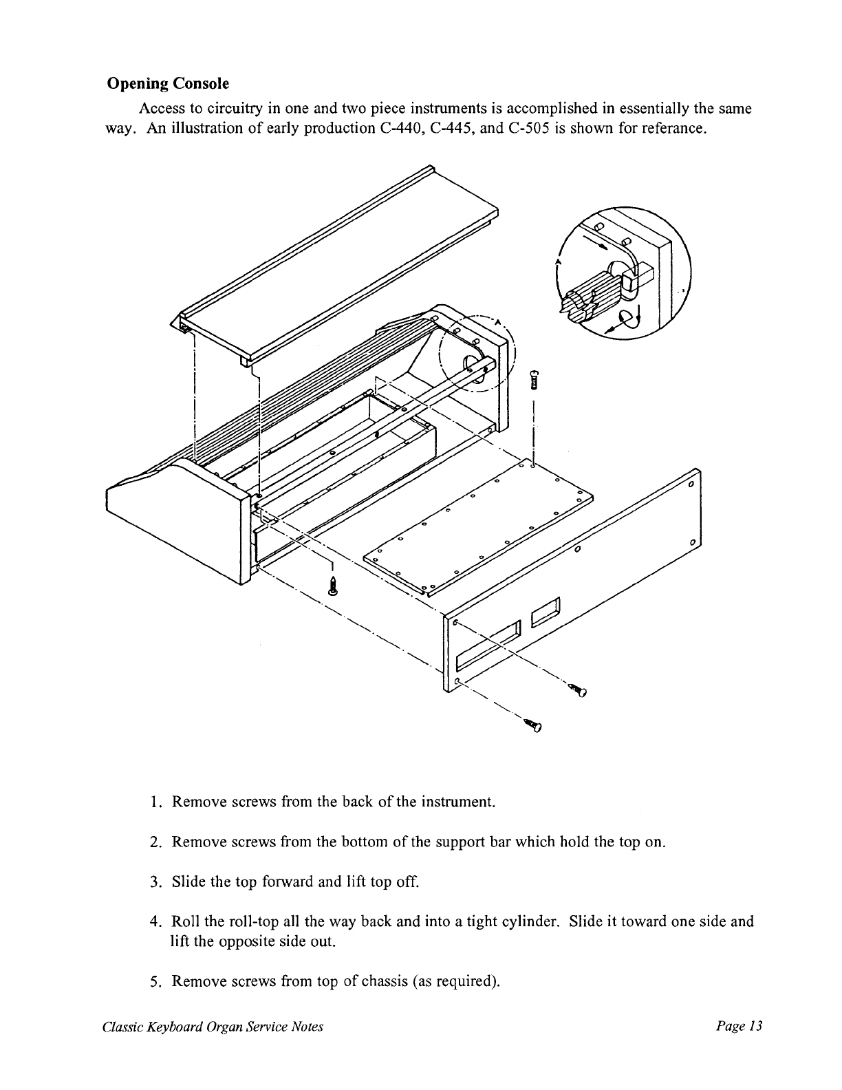
Opening Console
Access to circuitry in one and two piece instruments is accomplished in essentially the same
way.
An
illustration
of
early production C-440, C-445, and C-505 is shown for referance.
1.
Remove screws from the back
of
the instrument.
2. Remove screws from the bottom
of
the support bar which hold the top on.
3. Slide the top forward and lift top off.
4. Roll the roll-top all the way back and into a tight cylinder. Slide it toward one side and
lift the opposite side out.
5.
Remove screws from top
of
chassis (as required).
Classic Keyboard
Organ
Service Notes Page
13
Keyboard
and
Piston Rail Servicing
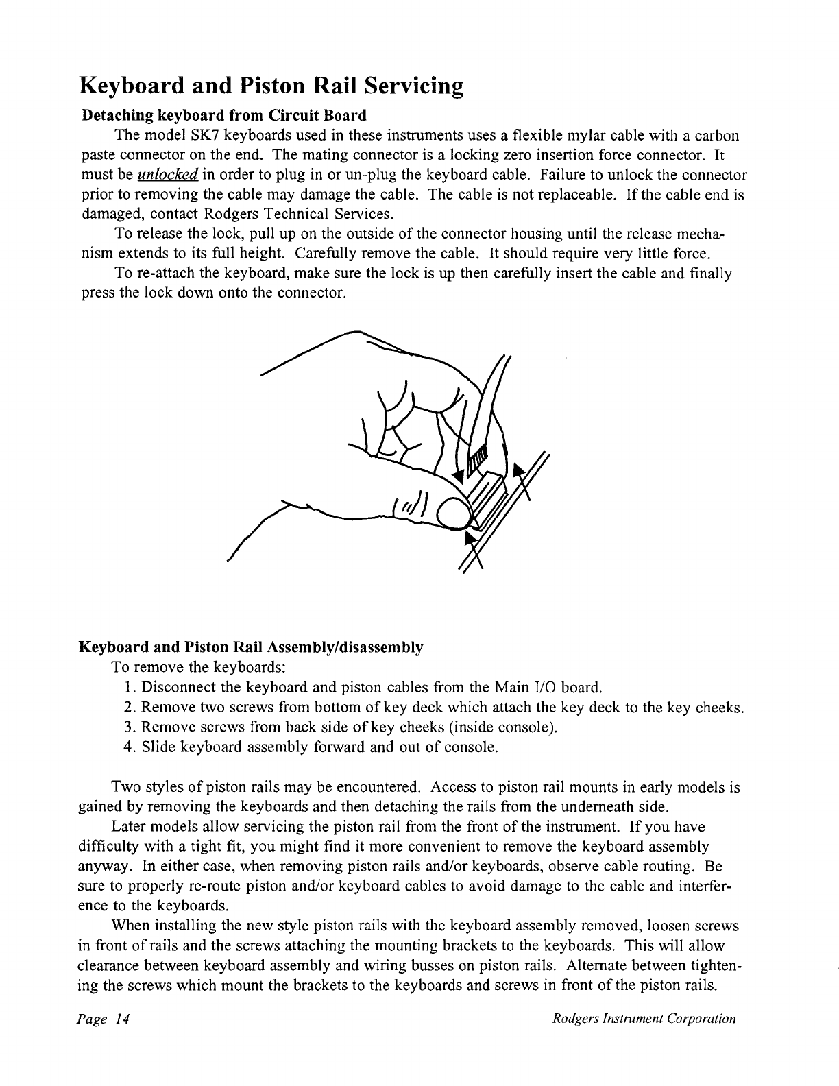
Detaching keyboard from Circuit Board
The model SK7 keyboards used in these instruments uses a flexible mylar cable with a carbon
paste connector on the end. The mating connector is a locking zero insertion force connector.
It
must be unlocked in order to plug in or un-plug the keyboard cable. Failure to unlock the connector
prior to removing the cable may damage the cable. The cable is not replaceable.
If
the cable end is
damaged, contact Rodgers Technical Services.
To release the lock, pull up on the outside
of
the connector housing until the release mecha-
nism extends to its full height. Carefully remove the cable.
It
should require very little force.
To re-attach the keyboard, make sure the lock is up then carefully insert the cable and finally
press the lock down onto the connector.
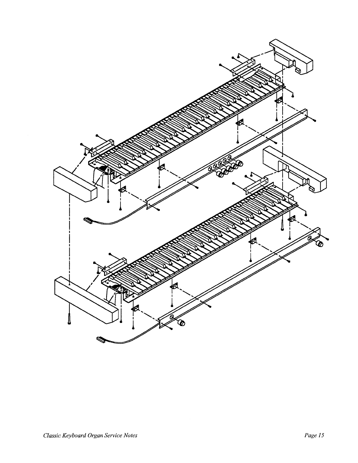
Keyboard
and
Piston Rail Assembly/disassembly
To remove the keyboards:
1.
Disconnect the keyboard and piston cables from the Main
110
board.
2. Remove two screws from bottom
of
key deck which attach the key deck to the key cheeks.
3.
Remove screws from back side
of
key cheeks (inside console).
4. Slide keyboard assembly forward and out
of
console.
Two styles
of
piston rails may be encountered. Access to piston rail mounts in early models is
gained by removing the keyboards and then detaching the rails from the underneath side.
Later models allow servicing the piston rail from the front
of
the instrument.
If
you have
difficulty with a tight fit, you might find it more convenient to remove the keyboard assembly
anyway. In either case, when removing piston rails and/or keyboards, observe cable routing. Be
sure to properly re-route piston and/or keyboard cables to avoid damage to the cable and interfer-
ence to the keyboards.
When installing the new style piston rails with the keyboard assembly removed, loosen screws
in front
of
rails and the screws attaching the mounting brackets to the keyboards. This will allow
clearance between keyboard assembly and wiring busses on piston rails. Alternate between tighten-
ing the screws which mount the brackets to the keyboards and screws in front
of
the piston rails.
Page 14 Rodgers Instntment Corporation
Classic Keyboard
Organ
Service Notes
Page
15

Individual Key Service
Individual keys on the keyboard can be removed and replaced. Replacement keys may be
purchased through Rodgers Instrument Corporation. Contact Classic Keyboard Technical Services
for more information.
The following is a step by step description
of
individual key replacement:
Key removal
I.
Remove Stopper (which is held on by double sticky tape).
Page
16
Rodgers Instrument Corporation
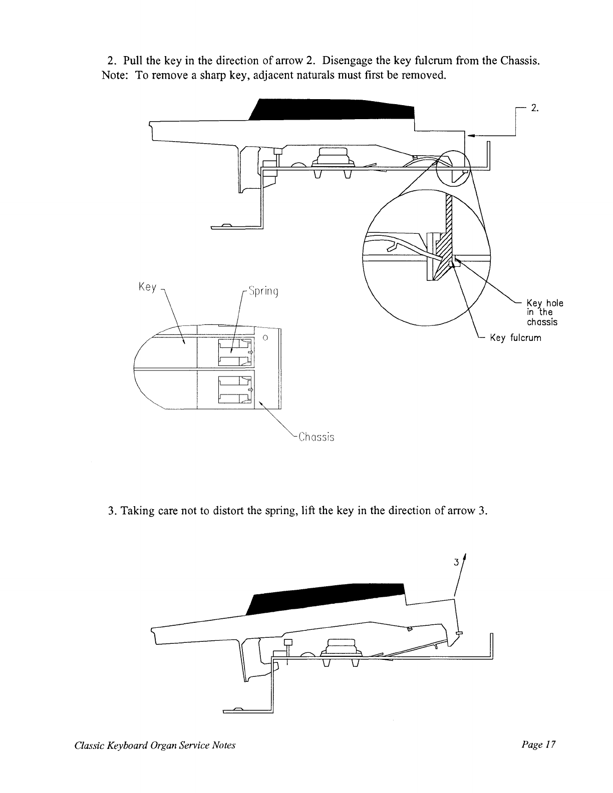
2. Pull the key in the direction
of
arrow 2. Disengage the key fulcrum from the Chassis.
Note: To remove a sharp key, adjacent naturals must first be removed.
Chassis
3. Taking care not to distort the spring, lift the key
in
the direction
of
arrow
3.
Classic Keyboard
Organ
Service Notes
Key
hole
in
the
chassis
Page
17
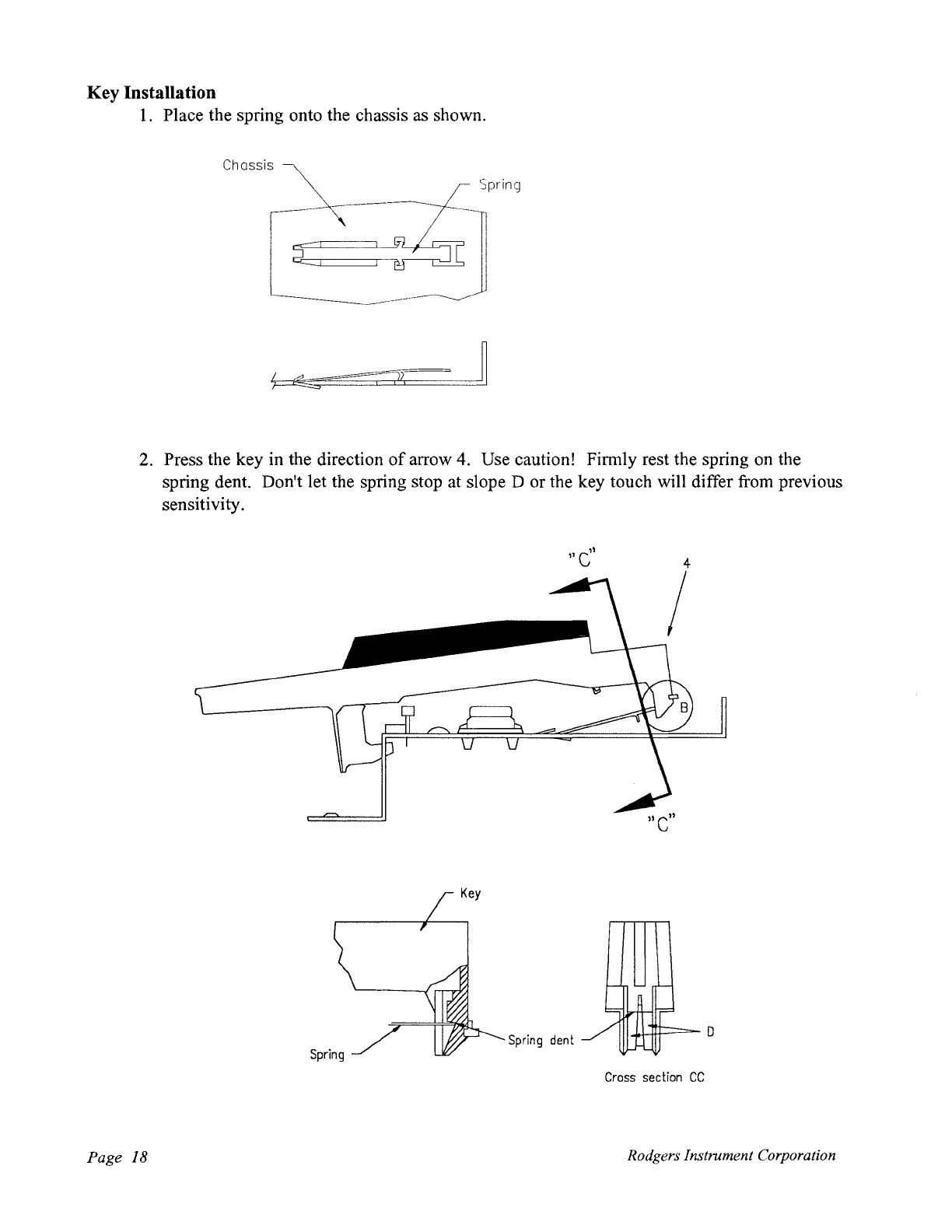
Key Installation
1.
Place the spring onto the chassis as shown.
Chassis
Spring
2. Press the key in the direction
of
arrow 4. Use caution! Firmly rest the spring on the
spring dent. Don't let the spring stop at slope D or the key touch will differ from previous
sensitivity.
Key
Spring
dent
Cross
section
CC
Page
18
Rodgers Instrument Corporation

3. Verify that there is clearance between the key fulcrum and the chassis at point E.
Chassis
4. Attach the stopper to chassis at point
F.
Classic Keyboard
Organ
Service Notes
Page
19

Tilt Tab Service
Tilt
Tab
Lamp
and
Switch Dis-assembly/Assembly
Tilt tab lamps may be removed by giving them one quarter turn in the counter clockwise
direction (as viewed from the back). The tilt tab encoder board may need to be removed to access
lamps hidden by it. Replace the lamp by reversing the operation.
To service the switches, the tilt tab board must be removed from the organ by removing the
mounting screws. The pivot bar may be detached from the circuit board by removing the rivits.
The rivits are released by pressing its center pin (from the switch side). Once the rivits are re-
moved, the pivot bar may removed and finally the silicon rubber switches. Do not handle the
conducting surfaces. Do not clean with solvent based cleaners as the carbon paste may dissolve.
Water or freon based cleaners without lubricants may be used, however. The switches should
measure less than one thousand ohms
on
resistance.
Tilt
Tab
PivotBar
I
-----------
<III:It[D
L~
1
Rivits
-1+----
--1
~
-Lamp
',fEJJi{)
Page
20
Rodgers Instrument Corporation
This manual suits for next models
8
Table of contents
Other Viscount Music Pedal manuals


