Shakmat Triple Steeple User manual

8HP Eurorack Module Built & designed in E.U. www.shakmat.com
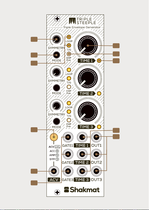
3
4
1
2
C
B
A
G
E
F
D

The triple steeple is a three-channel envelope generator with
control over time and symmetry. With five envelope modes,
linear or exponential response, CV control over time, an
assignable CV input, and internal normalizations, the module
will provide the generation of anything from basic envelope
shapes to complex modulation signals.
Introduction
The Triple Steeple requires a standard 2x5 pin eurorack power
cable. Make sure the red stripe on the cable matches the -12V
side of the Triple Steeple power header.
Installation
Assignable CV input
Gate inputs
Time CV inputs
Outputs
Symmetry potentiometer
Mode button
Mode LEDs
Time potentiometer
Shape LED
Activity LED
Assignable CV/
Level button

Modes
Each envelope has five different modes. To change mode, click
the corresponding channel's Mode button [B]. The two mode
LEDs [C] indicate the current mode:
02. Gated
The input accepts gate signals to generate
an attack-sustain-release envelope type.
01. Triggered
A rising edge triggers a one cycle envelope.
Time & Symmetry
Rather than having a classic attack-decay approach, the Triple
Steeple offers control of each envelope's timing and symmetry.
The time parameter, set via the Time potentiometer [D] and CV
input [3], is the sum of the attack and decay time. Modifying
the time parameter will change the attack and decay time by the
same amount.
The symmetry parameter defines the ratio of attack and decay
times via the Symmetry potentiometer [A]. Fully counterclo-
ckwise, the envelope has zero attack time, and there is only
decay. Turning the potentiometer clockwise reduces the decay
time as the attack increases. With the Symmetry potentiometer
[A] set at noon, the envelope is symmetrical (equal attack-decay
times). When the Symmetry potentiometer [A] is fully clockwise,
the envelope has an attack-only behavior without decay.

03. Looped
The envelope loops continuously.
A rising edge at the input resets it.
05. Clocked Loop
The envelope cycles and adapts its timing to the incoming
clock frequency. In this mode, time acts as a division
parameter, with available divisions of 1, 2, 3, 4, 5, 6, 7 and 8,
from fully counterclockwise to fully clockwise.
04. Gated Loop
The envelope loops continuously while a high gate signal is
present at the input. It instantly returns to its minimum
value when the gate signal disappears.
Envelope shape
Each envelope can have a linear (default) or exponential response.
Hold the Mode button [B] for 2 seconds to switch to an exponential
shape (white EXP LED [3] is on).
ACV Input & Level menu
To enter the Assignable CV input menu, press the ACV/ Level
Button [G] once (ACV/ Level button is on). You can now edit the
assignment of the ACV input [1] to control the symmetry or
amplitude of any of the three channels.
To switch between the different assignments of a particular
channel, press its corresponding Mode button [B]. The two mode
LEDs [C] and Shape LED [E] indicate the current mode as follows.

8v 5v 3v 0v
03. Accent
A high gate signal at the ACV input [1], at the beginning of
a cycle, the envelope amplitude will rise from the selected
level to 8v during its full cycle. This feature only works when
the channel level is set to a value other than 8v.
02. Amplitude
The ACV input [1] acts as a positive unipolar (0v to 5v)
control of the amplitude, which varies between 0v and
the amplitude selected in the level menu (see below).
This feature will not work if the selected level is 0v.
01. Symmetry
The ACV input [1] acts as a bipolar (-5v to +5v) control
of the symmetry, added to the value of
the channel's symmetry [A].
To enter the Level setting menu, press the ACV/ Level button [G]
a second time (ACV/ Level button is blinking). You can now edit
the range of the envelopes.
To exit the menus, and return to normal behavior (mode selection),
press the ACV/ Level button [G] a third time.
You can assign any parameters to one
of the three channels simultaneously.
Envelope 1
Envelope 2
Envelope 3
Output 3
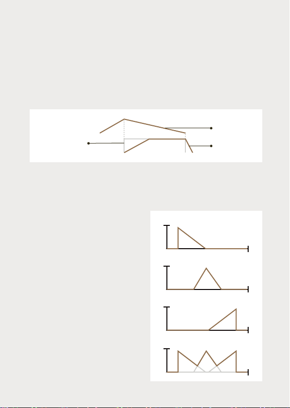
Input Normalization
Channels 2 and 3 receive the decay state of the previous channel
when nothing is inserted into their gate inputs [2]. This normaliza-
tion allows for different applications, as described in this manual's
patch ideas section. In this example, you can see the channel
1’s decay state acting as a gate for channel 2 in gate mode:
Output Normalization
Output 3 will output the
maximum of the outputs of the
previous channels unless a
cable is inserted to break this
normalization.
Inserting a cable into output 1 or 2
removes the channel's envelope
from the maximum function.
In this example, the third
channel's output [4] delivers
the maximum of the three
channels when the output jacks
of channels 1 and 2 remain
unplugged.
Channel 2
envelope
Channel 1
envelope
release state
Channel 1
envelope

Current State Storing
It is possible to save the current modes, response type, levels,
and ACV assignment by pressing and holding the ACV button
[G] for 2 seconds. All LEDs will blink to confirm the storage.
Patch Ideas
1. Percussive envelopes: set 3 channels of decay with
exponential response, enable accents, and start designing drum
sounds!
2. Cascaded clocked LFOs: configure the 3 channels in clocked
loop mode, insert a clock into channel 1 input, and create
modulation signals based on subdivisions (channel 1, 2 & 3) of an
incoming clock signal.
3. Delayed envelopes: trigger channel 1, give it some attack
time using the symmetry potentiometer [A]. Without anything
inserted into channel 2 input, envelope 2 will be triggered when
channel 1 attack phase ends. In other terms channel 2 will be
delayed by the attack time of channel 1.
4. Triggered ASR with control upon sustain time: in the same
order of ideas, trigger channel 1 in trigger mode with symmetry
fully counterclockwise, and without any cable inserted into its
gate input, put channel 2 in gate mode. While channel 1 is
decaying, channel 2’s signal will rise and hold its sustain phase.
When channel 1 decay is over, channel 2 will finally go into its
decay phase.

5. ADSR style envelopes: use channel 2 in trigger mode and
channel 3 in gate mode, then send the same gate signal in both
inputs. Set channel 3 amplitude to a lower level than channel 2.
Channel 2 settings will define the attack and decay, set channel 3
symmetry in order to have a longer attack time than channel 2.
Channel 3 decay defines the release time of the envelope. Do not
insert anything on channel 2 output, channel 3 output will deliver
the maximum amplitude of both envelopes providing an ADSR like
envelope.
6. Ratcheting envelope: set channel 1 in trigger mode and channel
2 in gated loop mode with a shorter time parameter. Send a trigger
into the first input, with nothing inserted into the second input and
listen to the second output. While the first channel is decaying the
second one will repeat its envelope. Controlling channel 2 amplitude
with channel 1 envelope leads to interesting results too!
.
7. Triple peak envelope: set channel 1 symmetry fully counterclo-
ckwise and time to 11 o'clock, channel 2 symmetry at noon and
time at noon, and channel 3 symmetry at 2 o'clock and time at 2
o'clock. With every channel in trigger mode, send a trigger into the
first input while using the third output. Result is an original
modulation source shaped as a multi peak envelope. Setting
different levels on each channel will also give more dynamic and
original results.
8. Pseudo random LFOs: Set the two first channels in loop mode
and insert a patch cable into the channel 2 input to break the
normalization. Send channel 1 output into channel 2 time CV input
and channel 2 output into channel 1 time CV input while multing
the two outputs. Use both outputs as modulation sources.
Attenuating the signal sent to the time CV inputs will lead to more
subtle results.

Specifications
Size
8 HP
Depth
21 mm
Current Draw
40 mA @ +12V
8 mA @ -12V
CV inputs
-5 to +5V
Gate inputs
0 to +5V
CV outputs
0 to +8V
Full cycle enveloppe timing
2.5 ms to 15 sec.
Minimum attack-decay time
200 µSec
www.shakmat.com
Table of contents
Other Shakmat Music Pedal manuals

Popular Music Pedal manuals by other brands


Mod
Mod THE PILEDRIVER Troubleshooting supplement

Electro-Harmonix
Electro-Harmonix DELUXE MEMORY MAN quick start guide

Wampler
Wampler Thirty something instructions

Behringer
Behringer ULTRA CHORUS UC100 user guide

PedalPCB
PedalPCB The Gent Overdrive Wiring diagram

MORLEY PEDALS
MORLEY PEDALS VAI-2ES Wiring diagram


