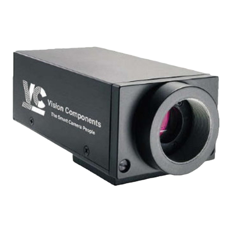
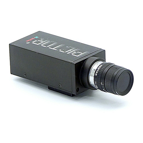
Vision Components VC40 Series User manual

Vision
Components
The Smart Camera People
VC40XX Hardware manual
Hardware Specifications for VC40XX Cameras
Revision 1.5 August 2005
Document name: VC40XX_HW.pdf
©Vision Components GmbH Ettlingen, Germany
©1996-2005 Vision Components GmbH Ettlingen, Germany

VC40XX.pdf – Hardware Documentation VC40XX Smart Cameras 2
Foreword and Disclaimer
This documentation has been prepared with most possible care. However Vision Components GmbH
does not take any liability for possible errors. In the interest of progress, Vision Components GmbH
reserves the right to perform technical changes without further notice.
Please notify support@vision-components.com if you become aware of any errors in this manual or if
a certain topic requires more detailed documentation.
This manual is intended for information of Vision Component’s only. Any publication of this document
or parts thereof requires written permission by Vision Components GmbH.
References
Since the VC40XX smart camera family employs a TI processor the programming environment and
functions for the VC20XX cameras can be used for this camera.
Please also consult the following resources for further reference:
Type of resource Name of file Download location
www.vision-comp.com
SW manual OS functions VCRT5.pdf Support->Reg. User Area->SW Manuals
SW manual Image Processing
Functions
VCLIB_2_0.pdf
VCLIB_300.pdf
Support->Reg. User Area->SW Manuals
Installation Manual InstallVC20XX_VC40XX Support->Customer Area->Getting
Started VC20XX …
Programming Tutorial Basic Programming Tutorial for
VC20XX and VC40XX
Cameras
Support->Customer Area->Getting
Started VC20XX …
Demonstration Source code Demo files
VC20XX+VC40XX …
Support->Customer Area->Demo Code
The Light bulb highlights hints and ideas that may be helpful for a development.
! This warning sign alerts of possible pitfalls to avoid. Please pay careful attention to sections
marked with this sign.
Copyright ©2005 by Vision Components GmbH Ettlingen, Germany
©1996-2005 Vision Components GmbH Ettlingen, Germany

VC40XX.pdf – Hardware Documentation VC40XX Smart Cameras 3
Table of Contents
1General Information 4
2Basic Structure 5
3Technical Specifications VC40XX 6
3.1 Technical Specifications VC4038 6
3.2 Technical Specifications VC4065 7
3.3 Technical Specifications VC4066 8
4VC40XX Camera Interfaces 9
4.1 LAN / Ethernet Interface 10
4.1.1 Pin Assignments LAN / Ethernet Interface 10
4.1.2 Available Accessories for LAN / Ethernet socket 10
4.2 Trigger-/ V24 (RS232)-/ Keypad Interface 11
4.2.1 Pin Assignments Trigger-/ V24 (RS232)-/ Keypad Interface 11
4.2.2 Trigger Cable 11
4.2.3 V24 (RS232) serial Cable 12
4.2.4 Y-Cable 12
4.2.5 Electrical Specifications of Trigger- / Serial-/ Keypad Interface 13
4.3 Power Supply and IO Interface 16
4.3.1 Pin assignments Power Supply and IO Interface 16
4.3.2 Electrical specifications Power Supply and IO Interface 16
4.3.3 Available Accessories / Cables for Power Supply and IO Interface 17
4.4 Video Output Interface 18
4.4.1 Pin Assignment of Video Output Interface 18
4.4.2 Available Accessories / Cables for Video Output Interface 18
5Accessories 19
6Programming VC40XX Smart Cameras 23
6.1 Programming the additional Serial Interface 23
Appendix A: Block diagram VC40XX Smart Cameras A
Appendix B: Overall Dimensions Housing VC40XX B
Appendix D: Drawing Camera Head VC40XX C
Appendix E: Spectral Transmission of IR Filter D
Index E
©1996-2005 Vision Components GmbH Ettlingen, Germany

VC40XX.pdf – Hardware Documentation VC40XX Smart Cameras 4
1 General Information
VC40XX Smart Camera series front view VC40XX Smart Camera series rear view
The VC40XX is one of the fastest Smart Cameras on the market. From the outside the VC40XX series
is identical with the VC20XX – the proven housing and Hirose connectors have remained unchanged.
However the internal electronics has been upgraded significantly.
The new TMS3200C64 processor from TI increases the computational power of the VC40XX almost
three times (to 3200 MIPS, equivalent to a 2.6 GHz Intel Pentium) compared with the VC20XX camera
family. In addition to that the VC40XX series features twice the internal memory (4Mbyte flash and 32
Mbyte RAM) and an SD card with 128 Mbyte replacing the MMC of the VC20XX.
Responding to customer demand, the VC40XX features both – 100 Mbit Ethernet and an additional
V24 (RS232) Interface. The RS232 interface connects to the Trigger socket. For this reason the
trigger input had to be slightly modified – existing trigger input circuits requires therefore adjustment.
Please refer to section 4.2 for details. All other interfaces have remained unchanged.
Like the VC20XX series the high speed trigger input of the VC40XX family allows jitter free taking –
even when inspecting fast moving objects. As the previous generation the VC40XX camera also
includes 24 V digital IO’s and a direct video output.
Like with all VC Smart Cameras with Texas Instruments DSP, the operation system VCRT allows
multi- tasking. This means for instance that user interface commands can execute in parallel without
stopping the inspection process. It is also possible to transfer live images via TCP/IP using a
background task.
Image acquisition can be done in the camera background. The VC20XX and VC40XX allow to perform
the three tasks of image capture, image transfer and image processing in parallel, greatly increasing
the amount of processed images per second.
The VC40XX family will be extended to match the feature variety of the VC20XX series in order to
offer the right camera for your application.
©1996-2005 Vision Components GmbH Ettlingen, Germany

VC40XX.pdf – Hardware Documentation VC40XX Smart Cameras 5
2 Basic Structure
The image is formed by a high-resolution progressive scan CCD sensor. One channel of video input is
digitized.
The VCSBC40XX has a direct video output.
The TMS320C64 DSP is one of the fastest 32bit DSPs. It features a RISC-like instruction set, up to 8
instructions can be executed in parallel, two L1 cache memories (16 Kbytes each) and a 128 Kbytes
L2 cache on chip. Its high speed 64-channel DMA controller gives additional performance. The DSP
uses fast external SDRAM as main memory. A flash EPROM provides non-volatile memory.
See Appendix A: Blockdiagram VC40XX Cameras
©1996-2005 Vision Components GmbH Ettlingen, Germany

VC40XX.pdf – Hardware Documentation VC40XX Smart Cameras 6
3 Technical Specifications VC40XX
3.1 Technical Specifications VC4038
Sensor: 1/3 “ SONY ICX424AL
eff. no. of pixels: 640(H) x 480(V)
Pixel size: 7.4 µm (H) x 7.4 µm (V)
Chip size: 5.79mm (H) x 4.89mm (V)
Integration: full-frame
Picture taking: program-controlled or triggered externally; full-frame /
63 frames per second
Binning 2 times binning, 126 frames/s, 640(H) x 240(V)
Shutter 5µs, 10 µs, 15 µs, 19 µs, … + steps of 31 up to 20s
Clamping: zero offset digital clamping
A/D conversion: 1 x 25 MHz / 10 bit
Input LUT 1024x8 bit (10bit →8 bit)
Image display: black-and-white, Pseudo Color from color lookup table
3x8Bit RGB, live image, still image, graphics
Overlay: 8-bit overlay with LUT, maskable
Processor: Texas Instruments TMS320 C64 signal processor 400
MHz
RAM: 32 MByte
Flash EPROM: 4 MByte
SD card 128 MByte (initially formatted to 16Mbyte)
Process interface: 4 inputs / 4 outputs, optically decoupled 24 V, outputs
4x500 mA
Trigger input: Fast 3-5 V TTL input and output.
Ethernet interface: 100Mbit Ethernet
Serial Interface: 115,200 bd serial RS232 communication port
Video output: RGB, 3x75 Ohm, 1 Vpp, SVGA output, HSYNC, VSYNC
separate
Horizontal frequency: 48.08 (VESA standard)
Vertical frequency: 72.19 (VESA standard)
Resolution SVGA: 800x600 (VESA standard)
Pixel frequency: 50.0 MHz (VESA standard)
©1996-2005 Vision Components GmbH Ettlingen, Germany

VC40XX.pdf – Hardware Documentation VC40XX Smart Cameras 7
3.2 Technical Specifications VC4065
Sensor: 1/2" SONY ICX415AL
eff. no. of pixels: 782(H) x 582(V)
Pixel size: 8.3(H) x 8.3(V) µm
Chip size: 7.48(H) x 6.15(V) mm
Integration: full-frame progressive scan
Picture taking: program-controlled or triggered externally; full-frame /
55 frames per second
Binning 2 times binning, 110 frames / s, 782(H) x 291(V)
Shutter 5µs, 10 µs, 15 µs, … + steps of 30.5 up to 20s
Clamping: zero offset digital clamping
A/D conversion: 1 x 33 MHz / 10 bit
Input LUT 1024x8 bit (10bit →8 bit)
Image display: black-and-white, Pseudo Color from color lookup table
3x8 Bit RGB, live image, still image, graphics
Overlay: 8-bit overlay with LUT, maskable
Processor: Texas Instruments TMS320 C64xx signal processor 400
MHz
RAM: 32 MByte
Flash EPROM: 4 MByte
SD card 128 MByte (initially formatted to 16Mbyte)
Process interface: 4 inputs / 4 outputs, optically decoupled 24 V, outputs
4x500 mA
Trigger input: Fast 3-5 V TTL input and output.
Ethernet interface: 100 Mbit Ethernet
Serial Interface: 115,200 bd serial RS232 communication port
Video output: RGB, 3x75 Ohm, 1 Vpp, SVGA output, HSYNC, VSYNC
separate
Horizontal frequency: 48.08 (VESA standard)
Vertical frequency: 72.19 (VESA standard)
Resolution SVGA: 800x600 (VESA standard)
Pixel frequency: 50.0 MHz (VESA standard)
©1996-2005 Vision Components GmbH Ettlingen, Germany

VC40XX.pdf – Hardware Documentation VC40XX Smart Cameras 8
3.3 Technical Specifications VC4066
Sensor: 1/3" SONY ICX204AL
eff. no. of pixels: 1024(H) x 768(V)
Pixel size: 4.65(H) x 4.65(V) µm
Chip size: 5.8(H) x 4.92(V) mm
Integration: full-frame progressive scan
Picture taking: program-controlled or triggered externally; full-frame /
30 frames per second
Binning 2 times binning, 60 frames/s, 1024(H) x 384(V)
Shutter 10 µs, 15 µs, 20 µs, …+ steps of 42.3 up to 20s
Clamping: zero offset digital clamping
A/D conversion: 1 x 33 MHz / 10 bit
Input LUT 1024x8 bit (10bit →8 bit)
Image display: black-and-white, Pseudo Color from color lookup table
3x8 Bit RGB, live image, still image, graphics
Overlay: 8-bit overlay with LUT, maskable
Processor: Texas Instruments TMS320 C64xx signal processor 400
MHz
RAM: 32 MByte
Flash EPROM: 4 MByte
SD card 128 MByte (initially formatted to 16Mbyte)
Process interface: 4 inputs / 4 outputs, optically decoupled 24 V, outputs
4x500 mA
Trigger input: Fast 3-5 V TTL input and output.
Ethernet interface: 100Mbit Ethernet
Serial Interface: 115,200 bd serial RS232 communication port
Video output: RGB, 3x75 Ohm, 1 Vpp, SXGA output, HSYNC, VSYNC
separate
Horizontal frequency: 63.98 kHz (VESA standard)
Vertical frequency: 60.02 kHz (VESA standard)
Resolution SVGA: 1280 x 1024 (VESA standard)
Pixel frequency: 108 MHz (VESA standard)
©1996-2005 Vision Components GmbH Ettlingen, Germany

VC40XX.pdf – Hardware Documentation VC40XX Smart Cameras 9
4 VC40XX Camera Interfaces
LAN / Ethernet Interface
PLC IO- / Power Supply Interface
Video OUT Interface
Trigger- / Serial RS232-/
Keypad- Interface
The VC40XX Smart Camera incorporates the following connector interfaces:
1. LAN / Ethernet Interface
2. Trigger- Serial V24 (RS232)- and Keypad Interface
3. PLC IO and Power Supply Interface
4. Video Output Interface
The pin assignments, electrical specifications as well as available accessories are shown for each
interface connector in the following sections.
Please also refer to the Product/Hardware/ Order Numbers for VC40XX Accessories/Cables page for
an up to date list of cables and further information available.
©1996-2005 Vision Components GmbH Ettlingen, Germany

VC40XX.pdf – Hardware Documentation VC40XX Smart Cameras 10
4.1 LAN / Ethernet Interface
4.1.1 Pin Assignments LAN / Ethernet Interface
Signal Pin rear view camera socket:
T+ 2
T- 1
R+ 6
R- 5
- 3
- 4
4.1.2 Available Accessories for LAN / Ethernet socket
Signal Pin (to cam.) Pin (to PC) Cable Color
20m patch cable
Cable Color
10m patch cable
T+ 2 1 yellow white/pink
T- 1 2 orange pink
R+ 6 3 white/green white/green
R- 5 6 green green
- 3 NC - -
- 4 NC - -
Refer to section 5 for a list of available cables with order numbers.
©1996-2005 Vision Components GmbH Ettlingen, Germany

VC40XX.pdf – Hardware Documentation VC40XX Smart Cameras
©1996-2005 Vision Components GmbH Ettlingen, Germany
11
4.2 Trigger-/ V24 (RS232)-/ Keypad Interface
The trigger interface now also incorporates a V24 (RS232) interface. For this reason there are 2
different cables:
-Trigger Cable (without second connector)
-Serial Cable (with D-sub connector on the other end)
There also is a new keypad available that connects to this Trigger / Serial interface.
The color coding for each core has been maintained from the VC20XX smart camera family.
Trigger and serial interface or trigger and keypad can be connected at the same time using the
following Y-cable:
4.2.1 Pin Assignments Trigger-/ V24 (RS232)-/ Keypad Interface
Pin Signal rear view camera socket:
1 V24 TxD Out
2 + 5V Out
3 GND
4 V24 RxD In
5 Trigger Out
6 Trigger In
61
2
3
4
5
Compared with the VC20XX Trigger interface, the former “Trigin –“ Interface has been
replaced with a “V24 TxD Out” signal allowing the use of a bidirectional serial RS232 Interface
(refer to section 6 for programming details). This means when replacing a VC20XX camera
with a VC40XX the trigger input circuit needs to be modified, or the camera can be damaged!
See the Electrical specifications in section 4.2.5 for details.
!
4.2.2 Trigger Cable
HIROSE 10A-7P-6SC
6-pi n. solder plug
Length: 5m
Cable: 0.14mm LiYCY 6 conductors
shielded, outside di ameter 5 mm
2
Pin Signal Cable Color1
1 V24 TxD Out green
2 + 5V Out brown
3 GND white
4 V24 RxD In pink
5 Trigger Out grey
6 Trigger In yellow
Equipped on one end with a Hirose plug, length 5m, 10m or 25m
Refer to section 5 for a list of available cables with order numbers.
1Note that the color coding for both cables has been chosen according to the VC20XX core colors.
For this reason the core colors of serial and trigger cables do not correspond to the same pin!

VC40XX.pdf – Hardware Documentation VC40XX Smart Cameras
©1996-2005 Vision Components GmbH Ettlingen, Germany
12
4.2.3 V24 (RS232) serial Cable
HIROSE 10A-7P-6SC
6-pi n. solder pl ug
Length: 5m
Cable: 0.14mm LiYCY 6 conductors
shielded, outside di ameter 5 mm
2
Pin Signal Cable Color
1 V24 TxD Out brown
2 + 5V Out pink
3 GND grey
4 V24 RxD In white
5 Trigger Out NC
6 Trigger In NC
Equipped on one end with a Hirose plug, length 5m, 10m or 25m and on the other end with a 9 pin D-
sub connector. This cable can also be ordered without the D-sub connector.
Refer to section 5 for a list of available cables with order numbers.
Refer to section 6.1 for information on programming the serial interface.
4.2.4 Y-Cable
Connectors:
1x HR10A-7P-6P, male connector 2x HR10A-7J-6S, female socket
Cable length: 0.5m
The color coding of this cable corresponds to the Trigger Cable described above.
Refer to section 5 for a list of available cables with order numbers.

VC40XX.pdf – Hardware Documentation VC40XX Smart Cameras 13
4.2.5 Electrical Specifications of Trigger- / Serial-/ Keypad Interface
The board features a dedicated fast TTL trigger input (for use as image capture trigger) and a fast TTL
trigger output (as strobe-light trigger). Since both signals are fast at a very low noise margin, it is
recommended to keep the cable as short as possible. Use shielded cable for this purpose.
Neither the trigger input nor the trigger output has an inbuilt-in photo coupler. Please ensure
that the electrical specifications of this section are met and provide galvanic isolation to trigger
input and output if necessary.
! Please note that input and output are not protected against over current. The output is neither
protected against short circuit nor reverse voltage spikes from inductive loads.
The trigger input assures constant delay without jitter.
Technical data of trigger input:
input voltage: 3-5 V (TTL, CMOS)
input current: 3mA @ 3V / 5mA @ 5V
limiting resistor: none
knee voltage: 1.5 V
reverse voltage protection: none
switching delay: Max. 2µsec + interrupt latency
Capture delay Approx 40µsec (constant), for jitter
free operation
Note the modified circuit of the trigger input, due to the additional RS232 interface. Old trigger input
circuits need to be modified in order to prevent damaging the trigger input of the VC40XX camera. The
trigger input now needs to be connected to GND (camera GND). The use of a transistor in the trigger
input circuit is recommended as shown in the following figures.
!
Please also note that the GND of the Trigger/ RS232 interface is not identical with the Power Supply/
PLC GND, GND IN com. (refer to section 4.3).
Suggested Trigger Input Circuit PNP
The 1kinternal pull down resistor is not included in the initial hardware release (delivery until end of
2005). Please provide external pull down resistor in case the trigger input stays high.
5V Out, Pin 2
Trig In, Pin 6
GND, Pin 3
Trigger Input Circuit Camera Circuit
1k
TTL Input
©1996-2005 Vision Components GmbH Ettlingen, Germany

VC40XX.pdf – Hardware Documentation VC40XX Smart Cameras 14
Suggested Trigger Input Circuit NPN
Trigger Input Circuit compatible to VC20XX and VC40XX cameras:
The trigger input circuit shown above can be used to connect both – the VC20XX and VC40XX smart
camera families.
5V Out, Pin 2 (VC20XX and VC40XX)
Trig In+, Pin 6 (VC20XX and VC40XX)
GND, Pin 3 (VC20XX and VC40XX)
Trig In - Pin 1 (VC20XX only!)
R
R
Trig In, Pin 6
GND, Pin 3
R
R
1k
TTL Input
5V Out, Pin 2
Camera Circuit
Trigger Input Circuit Camera Circuit
Trigger Input Circuit
©1996-2005 Vision Components GmbH Ettlingen, Germany

VC40XX.pdf – Hardware Documentation VC40XX Smart Cameras 15
Technical data of trigger output:
output voltage: max. 7V
output curent: max. 50mA
pull-up resistor: none, external resistor required
Note that the 100 Resistor protecting the +5V output of the VC20XX series has been replaced with
a self resetting poly fuse (see the following drawing).
©1996-2005 Vision Components GmbH Ettlingen, Germany

VC40XX.pdf – Hardware Documentation VC40XX Smart Cameras 16
4.3 Power Supply and IO Interface
This connector includes the camera Power Supply and digital PLC IOs.
4.3.1 Pin assignments Power Supply and IO Interface
Pin Signal rear view camera socket:
1 24V PLC
2 24V IN Cam
3 GND IN com.
4 INP 1
5 OUT 3
6 OUT 2
7 OUT 1
8 OUT 0
9 24V PLC
10 INP 3
11 INP 2
12 INP 0
4.3.2 Electrical specifications Power Supply and IO Interface
Power must be connected to the 12pin I/O connector. Note, that the voltage is 24V.
Camera power is regulated and galvanically separated inside the camera, so only an unregulated
power source of 24 V +/- 20% is required. The camera is, however, very sensitive to power supply
interruption. Please make sure, that the voltage never exceeds the limits of +/- 20% even for a short
period of time. In case of unstable power supply it is recommended to backup the power supply by a
capacitor or a battery large enough to prevent power interruptions.
The camera has several internal circuits to detect and protocol power failures. Used correctly these
internal flags can be used to perform a correct shutdown and close all open buffers (see below). This
feature is for emergency only and is not designed to handle very frequent interruptions.
There are different options for the connection of the power supply:
•Single voltage, with or without PLC signals, no shutdown
•Dual voltage, with or without PLC signals, shutdown
©1996-2005 Vision Components GmbH Ettlingen, Germany

VC40XX.pdf – Hardware Documentation VC40XX Smart Cameras 17
4.3.2.1 Single voltage, with or without PLC signals, no shutdown:
Signal Pin No. color connect to
24V IN Cam 2 red/blue 24V power supply
24V PLC 1 red 24V power supply
24V PLC 9 blue/pink 24V power supply
GND IN com. 3 black GND power supply
This option does not provide shutdown. Programmer must implement their own procedures for fail-
safe operation.
4.3.2.2 Dual voltage, with or without PLC signals, shutdown
Signal Pin No. color connect to
24V IN Cam 2 red/blue 24V backup supply
24V PLC 1 red 24V power supply
24V PLC 9 blue/pink 24V power supply
GND IN com. 3 black GND power supply
Here, the PLC voltage (24V PLC) is connected directly to the power supply. If a power failure occurs
or if power is switched off, the camera will detect this signal not being present. The internal flag
generated can be utilised to shut down the camera correctly and resume operation after a power
failure. The following procedures can be performed:
1. Stopping the operation of all programs and interrupts (no pictures will be taken any longer).
2. Saving all buffers (to multi-media card or flash EPROM).
3. Protocol time and date of the shutdown.
4. The procedure then waits for the backup voltage to disappear or main power to re-establish. If the
latter happens the program might be able to continue where it has stopped. (In this case there
may be some lost images = some parts not checked correctly)
The backup voltage must be able to supply specified voltage for a period of at least 100 msec.
4.3.3 Available Accessories / Cables for Power Supply and IO Interface
Equipped on one end with a Hirose plug jack, length 5m, 10m or 25m
Refer to section 5 for a list of available cables with order numbers.
©1996-2005 Vision Components GmbH Ettlingen, Germany

VC40XX.pdf – Hardware Documentation VC40XX Smart Cameras 18
4.4 Video Output Interface
4.4.1 Pin Assignment of Video Output Interface
Pin Signal rear view camera socket:
1 G GND
2 G Out
3 R GND
4 R Out
5 VS GND
6 VS Out
7 HS GND
8 B GND
9 B Out
10 HS Out
4.4.2 Available Accessories / Cables for Video Output Interface
HIROSE 10A-10P- 10P
10-pin. pins solder plug
Length: 5m
Cable: 5 x mini coaxial cable 75 Ohm
outside diam eter 7 m m
Signal Pin No. Connection
R Out 4 red signal
R GND 3 red shield
G Out 2 green signal
G GND 1 green shield
B Out 9 blue signal
B GND 8 blue shield
HS Out 10 white signal
HS GND 7 white shield
VS Out 6 gray signal
VS GND 5
g
ra
y
shield
Equipped on one end with a Hirose plug, length 5m, 10m and 25m.
Please order "with 2nd connector", if you need a DSUB15 connector at the other end.
Refer to section 5 for a list of available cables with order numbers.
©1996-2005 Vision Components GmbH Ettlingen, Germany

VC40XX.pdf – Hardware Documentation VC40XX Smart Cameras 19
5 Accessories
For interface cables and connectors available also consult the corresponding section in chapter 4 of
this manual.
Order numbers different camera models:
Article Description Order Number
VC4038E VK000230
Ethernet Cables (Refer to section 4.1.2):
Article Description Order Number Camera Connector Second Connector
5m LAN-C6-Cable VK000149
HRS connector female 6 pin
RJ45
10m LAN-C6-Cable VK000150 HRS connector female 6 pin RJ45
20m LAN-C6-Cable VK000151 HRS connector female 6 pin RJ45
Ethernet Cross Module VK000156
RJ45
RJ45 female socket
Trigger Cables (Refer to section 4.2.2):
Article Description Order Number Camera Connector Second Connector
5m Trigger-Cable / C6 VK000115
HRS connector male 6 pin
without connector
10m Trigger-Cable / C6 VK000164 HRS connector male 6 pin
without connector
25m Trigger-Cable / C6 VK000153 HRS connector male 6 pin
without connector
©1996-2005 Vision Components GmbH Ettlingen, Germany

VC40XX.pdf – Hardware Documentation VC40XX Smart Cameras 20
V24 (RS232) Serial Cable (Refer to section 4.2.3):
These cables differ from the serial VC20XX C6 cables!
!
Article Description Order Number Camera Connector Second Connector
5m V24 cable VK000243
HRS male 6 pin without connector
5m V24 cable with DSUB VK000244
HRS male 6 pin D-SUB 9 pin female
10m V24 cable VK000239 HRS male 6 pin without connector
10m V24 cable with DSUB VK000240 HRS male 6 pin D-SUB 9 pin female
25m V24 cable VK000241 HRS male 6 pin without connector
25m V24 cable with DSUB VK000242 HRS male 6 pin D-SUB 9 pin female
Y-Cable for connecting several cables to the Trigger / Serial Interface (Refer to section 4.2.4):
Article Description Order Number Camera Connector Second Connector
0.5m Y adapter cable VK000124
HRS male 6 pin
2 HRS female 6 pin
Power Supply and IO Interface Cables (refer to section 4.3.3):
Article Description Order Number Camera Connector Second Connector
5m Power / PLC-Cable C6 VK000008
HRS female 12 pin
without connector
10m Power / PLC-Cable C6 VK000114 HRS female 12 pin without connector
25m Power / PLC-Cable C6 VK000161 HRS female 12 pin without connector
©1996-2005 Vision Components GmbH Ettlingen, Germany
This manual suits for next models
3
Table of contents
Other Vision Components Digital Camera manuals
